Table of Contents
Advertisement
Quick Links
Advertisement
Table of Contents

Related Manuals for Bentel Security FIRECLASS 200


Summary of Contents for Bentel Security FIRECLASS 200
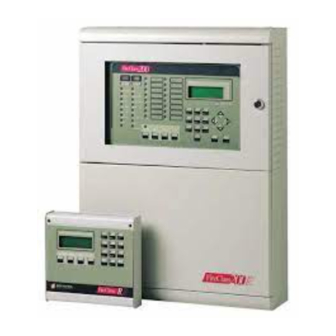
- Page 2 The FC200/SL Slave panel can function only when connected to a Fire- Class200 Master panel. BENTEL SECURITY srl reserves the right to change the technical featu- res of this product without prior notice. via Florida - Z.I. Valtesino - 63013 GROTTAMMARE (AP) - ITALY Installation manual: Analogue Fire Control Panel FireClass200 Istruzioni Inst.
-
Page 3: Table Of Contents
TABLE OF CONTENTS OVERVIEW Access Levels ..... . 7 Features ......7 Options with requirements . - Page 4 PROGRAMMING Auto (Autolearning) ....40 Connections: Loop 1 and Loop 2 ... . 41 Connections: Network .
- Page 5 Maintenance ..... . 72 Telephone ......73 Dial.
- Page 6 Analogue Fire Control Panel FireClass200...
-
Page 7: Overview
OVERVIEW Access Levels FireClass200 has several access levels for control panel management. Level 1 The Plexiglas window allows all persons to view the control panel status. Level 2A The door-lock protects the manual commands (RESET, SILENCE and LOGGER), and allows access to authorized key holders only. Level 2B Only User PINs (code of 1 to 5 digits) can Disable the Loop devices, Bell Outputs, Software Zones and Network devices. -
Page 8: Options With Requirements
Options with requirements The FireClass200 control panel performs the following options with requi- rements (complies with European norm EN54 part 2): Ø outputs to fire alarm routing equipment Ø co-incidence detection Ø fault signals from points Ø disablement of addressable points Ø... - Page 9 Phase 1 The telephone dialler will switch the telephone line. Phase 2 After 3 seconds the dialler will engage the telephone line. Phase 3 If the Dial-tone check option is enabled (refer to "Programming" chapter) the dialler will check for the dial tone, and when detected, will step to suc- cessive phase.
- Page 10 Analogue Fire Control Panel FireClass200...
-
Page 11: Parts Identification
PARTS IDENTIFICATION This chapter holds the full description of the main components and LEDs of the FireClass200. In most cases, the numbers in boldface refer to the parts shown in the tables and figures. Main unit (FireClass200) The Flashing status of certain LEDs is not dealt with in the following ta- ble, as it signals that the assigned event occurred and ended before the last rearming operation. - Page 12 ADDRESS ON: loss of a loop device. SAME ADDRESS ON: two devices on the same loop have the same address. ON: the SILENCE button has been used to places the SILENCEABLE Outputs in standby status. DAY mode SILENCE status will be held until SILENCE the SILENCE button is pressed again.
- Page 13 Figure 2 Main unit parts (external) PARTS IDENTIFICATION...
- Page 14 PART DESCRIPTION Jumper to enable programming: > programming enabled (default) > programming disabled 10 Keypad/Display board 11 Cable passage (3 x ∅ 30 mm) 12 Wall mounting holes (4 x ∅ 5 mm) 13 6 Output expander FC200/6OUT (optional - 2 maximum) 14 Telecom module FC200/COM (optional) 15 Main board 16 27.6 V - 4 A linear power supply/battery charger...
- Page 15 Figure 3 Main unit parts (internal) PARTS IDENTIFICATION...
- Page 16 The FireClass200 is available in two models: FC200/S - with 27.6 V - 2.5 A Power unit Switching power supply (see fig. 3a); FC200 - with 27.6 V - 4 A Linear po- wer supply (see fig. 3b). PART DESCRIPTION 24 Rivet to secure switching power supply 25 Power supply protection fuse: a) F3.15A 250V;...
- Page 17 PART DESCRIPTION 32 Connector for Keypad/Display 33 Connectors (2) FC200/6OUT Output expanders Jumper to enable data storage: > memory disabled (default) > memory enabled 35 Microprocessor 36 Connector for FC200/COM Telecom module 37 Reserved jumper 38 Extractable terminal boards 39 EOL Resistor (2.700 ohm / red-purple-red-gold) 40 Power-supply connector 41 F 6.3A 250V protection fuse against battery polarity inversion 42 F 3.15A 250V protection fuse for +AUX output...
-
Page 18: Output Expander (Fc200/6Out)
Output Expander (FC200/6OUT) PART DESCRIPTION Output status: LED OFF > corresponding Output in standby status LED ON > corresponding Output active Address assignment jumper: > Expander of Output no. 1 (Outputs no. 5 through no. 10) > Expander of Output no. 2 (Outputs no. 11 through no. 16) Loop Interface PART DESCRIPTION... -
Page 19: Telecom Module Fc200/Com
Telecom Module FC200/COM PARTS DESCRIPTION 52 Main board connector 53 Microphone 54 Loudspeaker connector 55 Terminal board for telephone line connections 56 Screws for backplate Earth cable with eyelet terminal ---- to be fixed to the screw on the backplate, and connected to the earth terminal of the Telecom Module Cable and connector for connecting the loudspeaker to the Telecom Module Plastic (ABS) gaskets to be used when mounting the loudspeaker to the... -
Page 20: Repeater
Repeater PART DESCRIPTION 61 Wall mounting holes (3) for (∅ 5 mm) 62 Cable duct holes (2) for (∅ 30 mm) 63 Microprocessor 64 Address assignment switches Figure 8 Repeater parts Analogue Fire Control Panel FireClass200... -
Page 21: Installation
INSTALLATION ATTENTION When installing the FireClass200 Fire Control Panel please respect all the local regulations in force. Follow the installation instructions carefully and refer to the figures on pa- ges 11 and 13. Ø Plan the system layout. Ø Lay the necessary cables. Ø... -
Page 22: Output Expander Installation
Use a hammer to remove the knockout, and pass the external cables through the hole 11. The cable conduit union with the box must be secured by HB flame class (or superior) lock nuts . Output expander Installation To install Output Expanders (FC200/6OUT) follow the instructions carefully and refer to the figures on pages 11 and 12. -
Page 23: Connections
Make the connections on the terminal board 38. Use the microswitches 55 to assign the Repeater address, as shown in the the following chart: MICROSWITCH No. ADDRESS No. Assign a different address to each Repeater. Connections Use shielded cable. One end of the cable must be connected to the control panel negative and the other left free. - Page 24 Conventional Input Line - Monitored and Silenceable. Up to 30 conven- tional fire devices can be connected to this line, such as: RF501t Optical Smoke Detectors, RT 101/102 Thermal Detectors, Manual Callpoints, Gas Detectors (max. 3). Terminal 10[+] must be connected to negative (terminal 9[ ]) by a 2,700 ohm resistor (red-purple-red-gold).
- Page 25 the connection of monitored devices activated by positive (24 V): Ø when an output is activated, positive (27.6 V) is present on terminal [+], and negative is present on terminal [--]. Ø These outputs can be bypassed by means of the relevant option from the DISABLE menu.
-
Page 26: Connection Of Addressable Analogue Devices
Connection of Addressable Analogue Devices The control panel has 2 Loops for the connection of Addressable Analogue Devices. Each Loop allows for the connection of up to 99 Addressable Analogue Fire Detectors and up to 99 Analogue Devices (Monitoring Modules, Con- ventional Zone Modules, Control Modules, Manual Callpoints and Soun- ders), for a total of 396 Analogue Devices. - Page 27 Figure 10 4 wire connection: a) Insulators; b) Compatible Analogue Devices (Fire De- tectors, Monitoring Modules, Control Modules, Conventional Zone Modules, Manual Callpoints). INSTALLATION...
-
Page 28: Connection Of Conventional Devices
2 or 4 wires can be used for the Loop connection: the connection type used for each Loop must be specified during the programming phase. Figure 9 illustrates the 2 wire connection to Loop 1. Figure 10 illustrates the 4 wire connection to Loop 1. The 2 wire connection does not permit more than 32 detectors per Loop. -
Page 29: Connection Of Repeaters And Slave Panels
Connection of Repeaters and Slave Panels Up to 8 FC200/REP Repeaters, and up to 7 FC200/SL Slave Panels can be connected to the RS485 port of the FireClass200 (terminals 15[+485] and 16[--485]): the power supply (27.6 V) to the Repeaters is supplied by terminals 17[+] and 14[ The FireClass200 must be programmed as Master, this will permit it to read the Repeaters and/or Slave Panels connected to its RS485 port. -
Page 30: Connection Of Output Devices
Connection of Output Devices The control panel has 2 Non-monitored outputs, 4 Bell Outputs (Monitored) and 8 Alarm Repetition Outputs (one for each Software Zone) for the con- nection of Output Devices. The Bell Outputs can be expanded to 10 or 16 by means of one or two FC200/6OUT Output Expanders. -
Page 31: Connection Of Telecom Module Fc200/Com
By pressing the SILENCE button, the Bell and the acoustic signalling devi- ce of the Siren will be stopped, whilst the Flasher and the optic signalling device of the Siren will continue to signal the Alarm status until the RESET button is pressed. -
Page 32: Power Connection
Power Connection The power systems on this control panel conform with EN54-4. Ø Connect the external power supply 230 V - 50 Hz to terminal 26: connect Earth to terminal [ ]; Neutral to terminal [N] and Line to terminal [L]. Ø... -
Page 33: Maintenance
Ø If parameter changes were made prior to power loss, the following messa- ges will be shown intermittently. FIRE CLASS 2ØØ FIRE CLASS 2ØØ No Devices Hit a Key acquired to take ØØ:ØØ 23/11/98 Mon control From this status it will be possible to access control panel management by pressing any button except RESET and TEST. - Page 34 Analogue Fire Control Panel FireClass200...
-
Page 35: Control Panel Management
CONTROL PANEL MANAGEMENT The FireClass200 can be managed from the main panel, or from an IMB compatible PC ---- connected locally via RS232 serial or via Telecom inter- face (FC200/SW software package and Telecom interface optional). Unauthorized access to manual control of the system is prohibited by the door-lock, which allows access to authorized key holders only (Access Le- vel 2A). -
Page 36: General Rules For Management From Panel
General rules for management from panel The FireClass200 can be easily managed via keypad, as per below. Alphanumeric Use the keypad to select the options from the menu; create Labels; enter keypad data and codes. Cursor keys Use the ← and → keys to scroll the parameters, and the ↑ and ↓ keys to select new values. -
Page 37: Access To Fireclass200 Management
Access to FireClass200 Management Press any key, except RESET and TEST, FIRE CLASS 2ØØ to access FireClass200 management from Scanning Loop Standby status. >> >> >> ØØ:ØØ 23/11/98 Mon The display will show the MAIN menu. FIRE CLASS 2ØØ 1= Programming 2= Modifying 3= Reading Parameter Select the required option, and refer to the relevant paragraph. - Page 38 Analogue Fire Control Panel FireClass200...
-
Page 39: Programming
PROGRAMMING Press 1 to access the PROGRAMMING FIRE CLASS 2ØØ menu from the MAIN menu. 1= Programming 2= Modifying 3= Reading Parameter Enter the Installer Code (the Factory de- Enter fault code is 00000). Each digits will be installer masked by the symbol Q. code ***** Press the ↵... -
Page 40: Auto (Autolearning)
Auto (Autolearning) The Auto option from the PROGRAMMING menu is for the Loop search on both the control panel, and the RS485 network of the MASTER panel. Autolearning must be run during control panel installation, and also after changes to the configuration of the Loops, Network, Bell Outputs and Tele- com module. -
Page 41: Connections: Loop 1 And Loop 2
If the control panel is programmed as MA- Analysis connections STER, the display will show ... 1)LOOP 1 2)LOOP 2 3)NET Select the required Loop (1 or 2) to access and program the parameters of the Loop Devices. Refer to the "Connections: Loop 1 and Loop 2" para- graph. - Page 42 Press the ↵ key to view the parameters of PRG:Smoke (Optic)%## the Devices at the lowest address. When Device: SENSOR devices share the same address, the sen- Z=ØØ Z=ØØ Z=ØØ Z=ØØ sor will be shown first. AT=5Ø **V=ØØ ** 1/Ø1 Position the cursor on the last parameter PRG:Smoke (Optic)%## on the bottom right then press the ↵...
-
Page 43: Connections: Network
Connections: Network The following example shows two Repeaters, connected to the Network, at addresses 1 and 8. Select the Network option from the CON- Analysis connections NECTIONS menu (press 3) and program 1)LOOP 1 the Network Device parameters. 2)LOOP 2 3)NET The display will show the Devices found NET Devices:... -
Page 44: Programming: Fire Sensors
Programming: Fire sensors Figure 16 shows the Fire detector parameters. Description This is the non-modifiable description of the Device type. Analogue Value This shows the non-modifiable real-time values measured by the Device. Label This is for the modifiable Device label (up to 20 characters can be ente- red). - Page 45 Figure 16 Fire detector parameters PROGRAMMING...
-
Page 46: Programming: Monitoring Modules
Programming: Monitoring modules Figure 17 shows the Monitoring module parameters. Ø Position the cursor on the third row of the display then press key 1 to ac- cess the parameters shown in figure 17b. Ø Most of the Monitoring module parameters are described in the "Program- ming: Fire sensors"... -
Page 47: Programming: Control Modules
Programming: Control modules Figure 18 shows the Control module parameters. Ø Position the cursor on the third row of the display then press key 1 to ac- cess the parameters shown in figure 18b. Ø Most of the Control module parameters are described in the "Program- ming: Fire detector"... -
Page 48: Programming: Conventional Zone Module
Associated Each Control module can be associated with 3 Input Points. The Control mo- Points dule will be activated when any one of its Input Points goes into ALARM sta- tus. For each Point it is necessary to indicate: Ø the Loop the Device is connected to (1 or 2);... -
Page 49: Programming: Repeaters And Slave Panels
Programming: Repeaters and Slave panels Figure 20a shows the Repeater parameters. Figure 20b shows the Slave panel parameters. The following parameters are valid for both. Description This is the non-modifiable description of the Device type. Label This is the modifiable Device label (up to 20 characters can be entered). The label is the Device identifier. -
Page 50: Devices
Devices The Device option from the PROGRAMMING menu allows parameter changes to the Devices found on Loops 1 and 2 during autolearning. The Device option is also for the parameters of the Conventional line (ter- minal [LC]), and those of the Bell Outputs on the Main board (terminals [Cx]) and on Expander Outputs (terminals [Cx]). -
Page 51: Conventional Line
To view the parameters of other Devices on the same Loop - follow the procedure described in the "Auto learning" paragraph. Press ESC to quit and step back to B. Conventional Line Figure 21 shows the parameters of the Conventional Line (terminal [LC]). Conventional Line programming is as per analogue sensors. -
Page 52: Bell Outputs
Bell Outputs Select Bell Outputs option from the DEVI- PRG: Devices CE menu to program the parameters of 1=LOOP 1 2=LOOP 2 the Bell Outputs on the Main board (termi- 3=Outputs BELL nals [Cx]), and those of the Bell Outputs 4=NET on Output Expanders (terminals [CX]). - Page 53 Figure 22 Bell Output parameters PROGRAMMING...
-
Page 54: Network
Network Select the NET option from the DEVICE PRG: Devices menu (press 4) for the parameters of the 1=LOOP 1 2=LOOP 2 Devices on the RS485 Network. Press 3=Outputs BELL ESC to quit and step back to the PRO- 4=NET GRAMMING menu. -
Page 55: Welcome Message (Mesini)
Installer Code The Installer Code accesses all control pa- Programming: nel menus. The default Installer Code is INSTALLER CODE 00000. enter the new code : XXXXX Enter the new Installer Code: each digit Programming: will be masked by the symbol Q. INSTALLER CODE enter the new code... -
Page 56: Zones
Zones Select the Zone option from the PROGRAMMING menu to access and program the Software Zone parameters. The same parameters can be programmed for all the Devices associated with a Software Zone. The Software Zone allows a group of Control Devices to be associated with several Input Points. -
Page 57: Option
Most of the Software Zone parameters are described in the "Programming: Fire sensors" paragraph. The following parameters are for Software Zones only. Delay Select ON to apply the Fixed Delay and PAS Delay to the Software Zone. The Fixed Delay will start when an alarm condition occurs on a Software Zone with the Delay enabled (ON). -
Page 58: Prealarm Time
Prealarm time An input Device programmed with Prealarm time will generate ALARM sta- tus when the prealarm time elapses. Prealarm status is signalled by: Ø an acoustic signal on the control panel and on the connected Repeaters; Ø blinking on the PREALARM LED; Ø... -
Page 59: Alarm Verify
Enter values of 00 through 99% with steps PRG: OPTION of 1%. The Warning Threshold default is WARNING 30%. Enter warning threshold: %3Ø Press the ↵ key to confirm, or ESC to quit without saving. Alarm Verify Select the Alarm Verify option for the Verify Time. The Verify Time will start when a Device exceeds the ALARM Threshold. -
Page 60: Drift Compensation
Drift Compensation The control panel performs periodical Alarm Threshold compensation on Devices with the Drift Compensation option enabled. This option is for the Drift Compensation value that requires maintenance. The control panel will request maintenance by means of a FAULT signal, and the relevant message on the display. -
Page 61: Timer And Special Timer
Timer and Special timer Sensors are particularly sensitive, therefore, when persons are present in the protected ambient the Alarm Threshold must be increased by the non- modifiable Default value (to allow for cigarette smoke etc.). The Timer and Special Timer can be programmed to control the ON-OFF times of the Alarm Threshold increase. - Page 62 The Timer will control sensors on the Loop with T setting only. The Special Timer will control sensors on the Loop with S setting only. H option The H option offers further flexibility to the Timers as it enables the Alarm Threshold increase on days which would normally be exempt (e.g.
-
Page 63: Delay
Delay Use the Delay option to access and program the Fixed Delay and PAS Delay. Fixed Delay The Fixed Delay will start when an alarm condition occurs on a Software Zone with the Delay option enabled (ON). The Fixed Delay will be signal- led by blinking on the Software Zone LED. -
Page 64: Pulse
Pulse The Pulse option is for the ON and OFF Times of the Bell Outputs. Select Pulse from the OPTION menu PRG: OPTION (press 8). Ø=P 1=W 2=V 3=D 4=T 5=S 6=H 7=D 8=Pulse 9=Extinction mode Enter the required ON and OFF Times: va- PRG: OPTION lues from 0 through 25.5 seconds, with PULSES (IPul) - Page 65 Time ON (TMP) This determines the time that Extinction Devices will be active. Enter va- lues from 0 through 20 minutes - 0 (zero) means that the Extinction Devi- ces will stop when the control panel is RESET. The default Time ON is 0 (TMP indefinite).
-
Page 66: System
System Select the Sys option from the PRO- 1=Auto 2=Devices GRAMMING menu (press 7) to access 3=PassWD 4=MesINI and program the system parameters. 5=Zones 6=Opt 7=Sys 8=Ver 9=Def Ø=Tel The display will show ... PRG: SYSTEM 1=Date/Time 2=Blink 3=Wire 4=SIL 5=WT 6=NET 7=Printer Select the required option, according to the following table, and refer to the... -
Page 67: Blink
Blink The analogue fire sensors are equipped with a LED which will blink when the control panel reads the detector status. Select the Blink option from the SYSTEM PRG: SYSTEM menu (press 2) to enable/disable the de- 1=Date/Time 2=Blink tector LED. 3=Wire 4=SIL 5=WT 6=NET 7=Printer... -
Page 68: Silence Mode
Silence mode The control panel SILENCE button will disable all Outputs in ALARM sta- tus (Bell Outputs and Control Modules), with the exception of the NON- Controlled Outputs (terminals [CM1-NC1-NO1] and [CM2-NC2-NO2]). Select the SIL option from the SYSTEM PRG: SYSTEM menu (press 4) to access and program the 1=Date/Time 2=Blink... -
Page 69: Walk Test
Walk Test The Walk Test allows the Installer to check proper functioning of the Input Points of each separate Software Zone. When a Software Zone ---- in Walk Test status goes into ALARM status, the control panel will activate the Alarm Outputs for a period of 1 to 15 seconds (depending on the number of sensors on the Loops). -
Page 70: Network
Network When the Fire control system is fully installed, and several control panels are connected via RS485: one of the control panels must be programmed as MASTER and all the others as SLAVES. Select the NET option from the SYSTEM menu to program the MASTER and SLAVES. -
Page 71: Printer
Printer A serial printer can be connected to the RS232 port of the control panel, for real-time printout of events. Select Printer from the SYSTEM menu PRG: SYSTEM (press 7). 1=Date/Time 2=Blink 3=Wire 4=SIL 5=WT 6=NET 7=Printer Select ON to enable or OFF to disable the PRG: SYSTEM Printer. -
Page 72: Factory
Factory The Factory option from the PROGRAMMING menu resets the manufactu- rers settings (Default) on the control panel. Select Def from the PROGRAMMING 1=Auto 2=Devices menu (press 9). 3=PassWD 4=MesINI 5=Zones 6=Opt 7=Sys 8=Ver 9=Def Ø=Tel The display will show ... PRG: FACTORY 1= Restore Default 2= Maintenance... -
Page 73: Telephone
To enable the Maintenance option, select PRG: FACTORY ON and enter the date (day, month and Maintenance year). The maintenance request will be si- Maintenance : OFF gnalled by FAULT status on the program- on date ØØ/ØØ/ØØ med date. Press the ↵ key to confirm, or ESC to quit and step back. Telephone The FC200/COM Telecom module (optional) can operate as either a Dial- ler or Digital Communicator ---- or both. -
Page 74: Dial. (Telephone Dialler)
Dial. (Telephone Dialler) Select Dial. from the PRG: TELECOM PRG: TELECOM MODULE MODULE menu (press 1) to program the 1)Dial. 2)Commun. Telephone module as a Telephone dialler. 3)T.Num. 4)Option The display will show the Dialler menu. 5)Remote Management Select Messages (press 1) to record up to PRG: TELECOM MODULE 8 voice messages of 11 seconds each (1 Dialler... - Page 75 Press ↵ to confirm or ESC to quit. Figure 26 Monitoring causes/events parameters PROGRAMMING...
-
Page 76: Commun. (Digital Telephone Communicator)
Commun. (Digital Telephone Communicator) Select Commun. from the PRG: TELE- PRG: TELECOM MODULE COM MODULE menu (press 2) to pro- Digital Communic. gram the module as a Telephone Commu- 1=Codes nicator. The display will show the Tel. 2=Causes / Events Communicator menu. - Page 77 The Alm. and Res. codes are not required for protocol 7 SIA 300 BAUD. The Res. code is not required for protocol 6 CONTACT-ID. Press ↵, ESC or the arrow keys to confirm and quit. Select Test to program the Test channel. PRG: T.Com.
-
Page 78: T.num (Telephone Numbers)
Select Causes / Events from the PRG: PRG: TELECOM MODULE TELECOM MODULE menu and assign Digital Communic. the events to the channels (1 through 8). Causes / Events The Telecom module will send the code to C:1,2,3,4,5,6,7,8 the programmed telephone numbers when the assigned events occur. - Page 79 The Acknowledge option allows 3 different operating modes: Ø SN (Successful Numbers): the control panel will perform the alarm cycle and check whether calls are successful or not, and will redial the telepho- ne numbers of successful calls during the subsequent cycles. Ø...
-
Page 80: Remote Management
Remote management Select Remote management from the PRG: TELECOM MODULE PRG:TELECOM MODULE menu (press 5) to enable (ON) or disable (OFF) Tele- Remote Managem.=OFF service. When the Teleservice option is ON the Installer will be able to service the control panel, and change the parameters via telephone. -
Page 81: Modifying
MODIFYING The Modifying option from the MAIN menu allows the user to: disable the Devices connected to the control panel; delete the Verify counters and log- ger; modify some of the parameters of the Telecom Module. Select the Modifying option from the FIRE CLASS 2ØØ... -
Page 82: Disable
Disable The Disable option from the MODIFYING menu can Disable or Enable: Ø the Devices on the loop (Monitoring Devices or Control Devices); Ø Bell Outputs; Ø Software Zones; Ø Devices on the Network (Repeaters or Slave panels). The DISABLE LED will go ON when one or more of the above mentioned is/are disabled. - Page 83 FAULT status will be generated when the Repeater is re-enabled. Slave panels A Disabled Slave panel cannot generate NETWORK ALARM or NET- WORK FAULT status. Loss of Disabled Slave panel from the Network will not generate FAULT status. Ø To clear FAULT status - generated by the loss of a Slave panel - Disable the Slave panel in question.
-
Page 84: Delete Verify
Step back to C. Conventional To enable or disable the Conventional line MOD: Devices L1 line (terminal 10[LC+]): position the cursor on Enter Address the L1 Detector space and press the ↑ Sensors 1/ZC key. Modules L1: 1/__ Non-Configured If an invalid address is entered, the display DEVICES LOOP1 will show an error message. -
Page 85: Delete Logger
Delete logger The Delete logger option from the MODIFYING menu deletes the con- tents of the logger. Select the Delete logger option from the Modifying: MODIFYING menu (press 3). 1=Disable 2=Del.Ver.3=Del.Log 4=Telecom Module Press the ↵ key to delete the contents of Mod: Clear Logger the logger, or press ESC to quit and step back to the MODIFYING menu. - Page 86 Enter the identifier number of the message Mod: Telecom Module and press 1 to listen. The display will show Listen Message >>>>>>> Esc=End Press ESC to stop the message and step Mod: Telecom Module back. Select Record (press 6) to record or Recording change messages.
-
Page 87: Reading Parameter
READING PARAMETER Use the Reading Parameter option from the MAIN menu to view all the control panel parameters, and to print the logger contents. Select the Reading Parameter option FIRE CLASS 2ØØ from the MAIN menu (press 3). No access 1= Programming code is required, as viewing and printout 2= Modifying... -
Page 88: Options
Position the cursor on Loop 1 then press the ↑ key to view the parameters of the Conventional Line. If a valid address is entered the display will show the relevant data as de- scribed in the "PROGRAMMING". Press the ← or → key to view the parameters of the other Items of the same type, or press ESC to enter another address (step C). -
Page 89: Logger
The display will show the control panel Fire Class 2ØØ version. Press ESC to step back to the version READING PARAMETER menu. 3.Ø Logger The FireClass200 Logger can store the last 200 events. When the logger is full the oldest event will be deleted automatically to make space for the new event. -
Page 90: Logger Data
... the most recent event will be shown. ZONE ALARM FIRE CLASS 2ØØ Software Zone 15:Ø9 13/Ø7/99 Ø1 When the → key is pressed on the most recent event, the control panel will emit an error signal. No event At step B - if the logger is empty (no ØØØ... -
Page 91: Print
Print The Print option from the READINGS menu prints all the logger contents on the connected printer. Select the Print option from the REA- READINGS: DINGS menu (press 5) or press ESC to 1=Dev./Zones/Outputs step back to the MAIN menu. 2=Opt.3=Ver.4=Log. -
Page 92: Telecom Module
Press the ↵ key to suspend the Print or press ESC to step back to C. Print The Programming option from the PRINT menu is reserved for future use. Programming If the Programming option is selected from the PRINT menu. READINGS Print: 1= Logger... - Page 93 Select Messages (press 2) to listen to the Rd. :Telecom Module messages recorded during the program- Message ming phase of the Telecom module. A = Listen Select Remote management (press 3) to enable or disable (ON / OFF) Te- leservice. The display will show ...
- Page 94 Analogue Fire Control Panel FireClass200...
-
Page 95: Quick Guide
QUICK GUIDE This quick guide holds all the information required by installers with some knowledge of the FireClass200 fire control panel, or of fire control panels in general. General features Below are some of the technical features of the terminals on the Main bo- ard, Output Expanders and Repeaters. -
Page 96: Terminals
Terminals The following charts hold: Ø a brief description of the terminals on the Main Board, Output Expanders and Repeaters; Ø the voltage present during the different conditions of each terminal; Ø the maximum voltage (in amperes) that can circulate on each terminal. Main board TERM. - Page 97 Output Expander TER. DESCRIPTION v(V) i(A) [C5/11] PROGRAMMABLE OUTPUTS - Controlled: ↓ output active è positive on [+] and negative on [--] 27.6 1.5 (3) [C10/16] Repeater TER. DESCRIPTION v(V) i(A) [+485--] SERIAL BUS POWER SUPPLY (input): terminals for the power supply to the Repeater 4[24V] 27.6 0.18...
- Page 98 Notes ___________________________________________________________ ___________________________________________________________ ___________________________________________________________ ___________________________________________________________ ___________________________________________________________ ___________________________________________________________ ___________________________________________________________ ___________________________________________________________ ___________________________________________________________ ___________________________________________________________ ___________________________________________________________ ___________________________________________________________ ___________________________________________________________ ___________________________________________________________ ___________________________________________________________ ___________________________________________________________ ___________________________________________________________ ___________________________________________________________ ___________________________________________________________ ___________________________________________________________ ___________________________________________________________ ___________________________________________________________ ___________________________________________________________ Analogue Fire Control Panel FireClass200...
- Page 99 Notes ___________________________________________________________ ___________________________________________________________ ___________________________________________________________ ___________________________________________________________ ___________________________________________________________ ___________________________________________________________ ___________________________________________________________ ___________________________________________________________ ___________________________________________________________ ___________________________________________________________ ___________________________________________________________ ___________________________________________________________ ___________________________________________________________ ___________________________________________________________ ___________________________________________________________ ___________________________________________________________ ___________________________________________________________ ___________________________________________________________ ___________________________________________________________ ___________________________________________________________ ___________________________________________________________ ___________________________________________________________ QUICK GUIDE...
Need help?
Do you have a question about the FIRECLASS 200 and is the answer not in the manual?
Questions and answers