
Related Manuals for ICE Games KNOCK OUT PUNCH


Summary of Contents for ICE Games KNOCK OUT PUNCH
- Page 1 OWNERS AND SERVICE MANUAL INNOVATIVE CONCEPTS IN ENTERTAINMENT INC. 10123 MAIN STREET, CLARENCE, NY 14031 SERVICE: 1-716-759-0360 FAX: 1-716-759-0884 E-MAIL: service@icegame.com WEBSITE: www.icegame.com...
-
Page 2: Table Of Contents
TABLE OF CONTENTS INTRODUCTION……………………………...…..…..PAGE 3 GAME FEATURES GAME PLAY ASSEMBLY……………….……….…………..…..…..PAGE 4 & 5 BEFORE YOU BEGIN TOOLS NEEDED INSTALLATION SET-UP / TESTING.……………………………….…..PAGE 6 - 8 SETTING A.C. LINE VOLTAGE ADJUSTMENTS ADJUSTING VOLUME FINAL ASSEMBLY ... -
Page 3: Introduction
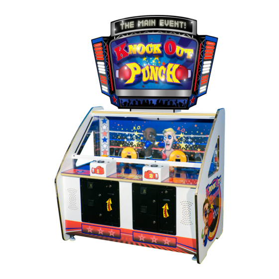
INTRODUCTION GAME FEATURES GAME PLAY Thank you for your purchase of the new KNOCK The player inserts their money into the game to be- OUT PUNCH™ redemption game from I.C.E. gin. Behind the row of boxers are round displays that either will show a count down timer or it will show The game is constructed of a quality 7 ply MDO ply- how many boxers you hit depending on how you... -
Page 4: Assembly
ASSEMBLY BEFORE YOU BEGIN WARNING: WHEN INSTALLING THIS GAME, A 3 PRONG GROUNDED A.C. RECEPTACLE MUST BE USED. FAILURE TO DO SO COULD RESULT IN INJURY TO YOURSELF OR OTHERS. FAILURE TO USE A GROUNDED RECEPTACLE COULD ALSO CAUSE IMPROPER GAME OPERATION, OR DAMAGE TO THE ELECTRONICS DO NOT DEFEAT OR REMOVE THE GROUNDING PRONG ON THE POWER CORD FOR THE SAME... - Page 5 ASSEMBLY Snap the fuse holder assembly back into the SETTING A.C. LINE power module. VOLTAGES Plug the power cord back into the receptacle The game comes with 4 available line voltage set- in the power module, and into the wall outlet. tings as described below.
-
Page 6: Set-Up / Testing
SET-UP / TESTING SAFETY PRECAUTIONS PROGRAMMING BUTTON WARNING: WHEN INSTALLING THIS GAME, A 3 Press this button to enter or exit the PROGRAM- PRONG GROUNDED A.C. RECEPTACLE MUST MING mode. You will notice when you are in the BE USED. FAILURE TO DO SO COULD RESULT Programming mode, as the displays will change. - Page 7 SET-UP / TESTING MODE 1 MODE 5 (GAME LENGTH) (VALUE OF XX) This mode determines how long the game lasts in This option determines the number of tickets to dis- SECONDS. The range for this value is 1-60. pense each time a dispense order is given by OP- The default value for this game is "15"...
- Page 8 SET-UP / TESTING MODE 9 (DISPLAY TYPE) This option determines what information the round displays will show during game play. The display can show either a count down timer or how many boxers the player has hit. 0= Count Down Timer displayed 1= How many boxers you hit The default value for this option is "0"...
-
Page 9: Quick Troubleshooting
QUICK TROUBLESHOOTING GAME WILL NOT START NO A.C. POWER CHECK POWER AT A.C. RECEPTACLE POWER MODULE SET INCORRECTLY CHECK VOLTAGE SETTING FUSE BAD IN POWER MODULE CHECK OR REPLACE FUSE FUSE BAD ON MAIN P.C. BOARD CHECK OR REPLACE FUSE NO CREDITS INSERT PROPER AMOUNT OF COINS BAD COIN MICRO SWITCH... -
Page 10: Repair
BACKGROUND PUNCHING GLOVE ASSEMBLY OVERVIEW The KNOCK OUT PUNCH™ game has been de- signed to be as easy as possible to repair. The punching glove system is designed for high reli- The boxer belt can be easily adjusted while in the ability and safety. - Page 11 GAME REPAIR If you see that the thermal switch is good, check to 3. Remove the 2 square drive screws that hold the see that the coil and the diode on the coil are good. cardboard fan shroud in place. Disconnect the coil and unsolder 1 side of the diode.
- Page 12 GAME REPAIR BOXER BELT ASSEMBLY 4. Remove the wires that are connected to the D.C. ADJUSTMENT AND REPAIR motor. They are located on the left side of the game, shown below with the arrow. There are two different adjustments that should be occasionally performed on the belt assembly.
- Page 13 GAME REPAIR 7. Loosen the 4 adjusting bolts on BOTH ends of 3. Remove the covers that are held in place with the assembly to loosen up the duck belt. Velcro as shown previously. 4. Remove the wires that are connected to the D.C. motor as shown previously.
- Page 14 GAME REPAIR MOTOR MOUNTING SCREWS BOXER BELT ADJUSTMENT 11. On the IDLER ROLLER side of the assembly, 1. PRELIMINARY ADJUSTMENT - Loosen the 4 pull the belt to the side and loosen the 2 Allen bolts that hold the boxer belt assembly to the set screws that hold the drive roller to the motor cabinet.
- Page 15 GAME REPAIR BULB REPLACEMENT (Cabinet) BALLAST REPLACEMENT 1. Remove cover glass by removing the 4 Allen 1. Open back door of marquee. screws that hold the glass retainer. 2. Located at the top is the ballast “WORKHORSE 5” to power the marquee bulbs. 3.
- Page 16 GAME REPAIR 2. Remove the two mounting bolts that hold the round display to the cabinet. MAINTENANCE Maintenance is easy, as the game requires very little service under normal use. For your customers to get the greatest enjoyment from the game, please per- form the following periodically: ...
-
Page 17: Electrical / Electronic Repair
PARTS LISTING MECHANICAL PARTS ELECTRICAL / ELECTRONIC PARTS FP1019 LEVELER FOOT HD1052 SWIVEL CASTER E00211 LOW TICKET SWITCH WA5001 TRIPLE COIN DOOR 2005 LIGHT BULB, #906 WK1001-P700 CONTROL BOX 2026 THERMAL SWITCH WK1114 RAMP (BOXER LIFT) 2364X FAN ASSEMBLY WK1020-P802 PUNCH ASSEMBLY BRACKET HH5005 TICKET DISPENSER WK1022... -
Page 23: Schematics & Wiring Diagrams
WK1020X WK1024 Plunger WK2029X Solenoid... -
Page 26: Warranty Information
WARRANTY POLICY I.C.E. Inc warrants all components in new machines to be free of defects in materials and workmanship for the period listed below: ■ 180 days on Main PCB’s, Computers & Motors ■ 1 year on all LCD monitor panels ■...
Need help?
Do you have a question about the KNOCK OUT PUNCH and is the answer not in the manual?
Questions and answers