
Related Manuals for Parker KA-MT 10-95/D3


Summary of Contents for Parker KA-MT 10-95/D3
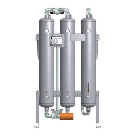
- Page 1 Adsorption dryer KA-MT 10-95/D3 ( Generation - 3) Operating manual 30/02/2020 rev02 EN Cod: 398H271980...
-
Page 3: Table Of Contents
Instructions for use of the dongle ................... 35 Daily maintenance tasks ......................36 Monthly maintenance tasks ....................37 Maintenance work to be completed every 12 months ............41 Notes on further maintenance work ..................43 Identify and eliminate faults Summary of faults ........................44 KA-MT 10-95/D3... - Page 4 EN | User Manual Annex with technical documentation Technical data ......................... 49 Replacement and wear part list ....................50 Tightening torque values ......................52 Logic control diagram ......................53 Flow diagram .......................... 55 Dimensional drawing ......................56 KA-MT 10-95/D3...
-
Page 5: Machine Passport
Further important data on the dryer such as the details on the permissible operating pressure and the electrical connection are found on the type plate (for position of the type plate see page 8 ) KA-MT 10-95/D3... -
Page 6: General Information
General information Manufacturer’s details Name and address Parker Hannifi n Manufacturing S.r.l. Sede Legale: Via Privata Archimede, 1- 2009 Corsico (MI) Italy Sede Operativa: Gas Separation and Filtration Division EMEA - Strada Zona Industriale, 4 35020 S.Angelo di Piove (PD) Italy tel +39 049 971 2111- fax +39 049 9701911 Web-site: www. -
Page 7: About These Operating Instructions
These operating instructions must be continuously available at the site where the dryer is used. We recommend to prepare a copy and to keep the same in a safe and freely accessible place next to the dryer. Keep the original document in a safe place. KA-MT 10-95/D3... -
Page 8: For Your Own Safety
◊ When fi lling drying agents, wear a dust mask and eye protection! ◊ If a spillage occurs, any spilt drying agent must be taken up immediately. There is a risk of skidding! KA-MT 10-95/D3... -
Page 9: Intended Use Of The Dryer
Suspected misuse The dryer must not be misused as a climbing aid! Pipes, valves, and similar fi ttings have not been designed for such loads. They could fracture, tear off, or become damaged in another way. KA-MT 10-95/D3... -
Page 10: Signs, Instruction Plates And Danger Zones At The Dryer
Type plate of the dryer Vessel plate Front view Please note the above plates and instructions attached to the dryer. Ensure that they are not removed and are always readable. KA-MT 10-95/D3... - Page 11 When working at the oil indicator, always wear protective goggles. KA-MT 10-95/D3...
-
Page 12: Transportation, Installation And Storage
Inform the haulier immediately in writing of any damages. Contact the manufacturer urgently in order to report the damage. Warning! A damaged dryer must not be taken into operation! Damaged components may lead to functional faults and possibly cause further damage. KA-MT 10-95/D3... -
Page 13: Transporting And Installing The Dryer
Therefore, always transport the dryer on a lifting or forklift truck. The dryer should only be transported in an upright position. Secure the dryer on the lifting or forklift truck against sliding movements. Transport the dryer to its installation site. KA-MT 10-95/D3... - Page 14 I: Transport lugs on pressure vessel II: Installing by crane Anchoring the dryer Use suitable attachment material to anchor the dryer to the fl oor. In the case of vibrating fl oors: place the dryer on suitable vibration dampers. KA-MT 10-95/D3...
-
Page 15: Storing The Dryer
If you wish to take the dryer back into service after an extended period of sto- rage, please proceed as described for its fi rst commissioning and start-up (see page 26). Store drying and purifying agents Do not store drying agents in the open air. Protect drying and purifying agents against humidity. KA-MT 10-95/D3... -
Page 16: Technical Product Description
To this end, the two chambers alternate between different operating modes. Whilst in one vessel, compressed air is de-humidifi ed (adsorption), in the other vessel the humid drying agent is prepared for another charge (regeneration). These two states, which run in parallel during compressed air preparation, are described below. KA-MT 10-95/D3... - Page 17 This separate regeneration air fl ow is fed through the depressurised chamber. The humidity stored in the drying agent is taken up by the air fl ow and expelled into atmosphere via the muffl er. Here, regeneration is shown in the right vessel. KA-MT 10-95/D3...
- Page 18 When the drying agent in the adsorbing chamber has taken up a suffi cient level of humidity, then the switchover between the vessels will be effected between the vessels. Following switchover, the above-described process is repeated, with the adsorption and regeneration now taking place in the respective different vessel. KA-MT 10-95/D3...
-
Page 19: Available Options
This replacement optimizes the regeneration air consumption and therefore restores the energy effi ciency of the dryer. To receive more information on this conversion, please contact the manufacturer. KA-MT 10-95/D3... -
Page 20: Installation
The data required to meet these preconditions are contained in the technical documentation attached in the annex. Warning! If the above preconditions are not complied with, a safe operation of the dryer cannot be assured. Also, the functionality of the dryer may be detrimentally affected. KA-MT 10-95/D3... -
Page 21: Connect Piping
If you fi t a bypass line (8) with additional shutdown valve: Fit the line such that, when carrying out maintenance work on the dryer, the line system can continue to be supplied with compressed air. KA-MT 10-95/D3... -
Page 22: Installing The Electrical Connection
Connect electrical cable to device the switchbox. adapter In all phases the dryer must be protected against short circuits by means of fuses. In order to relief cable strain, re-tighten the PG union. KA-MT 10-95/D3... - Page 23 Connect the lines of the fault signalling system to relay K5 (see circuit diagram). Check bolt connections Before the initial start-up: Check all unions and bolt connections as well as the terminals in the control cabinet for secure seating; re-tighten if necessary. KA-MT 10-95/D3...
-
Page 24: Start-Up
◊ owner-end and pressurised parts such as safety valves or other devices are not blocked up by dirt or paint, ◊ all compressed air system parts which are pressurised (valves, hoses etc.) are free from wear symptoms and defects. KA-MT 10-95/D3... -
Page 25: Setting Times Of The Operating Phases
— with compressor synchronisation — in variable cycle mode (i.e. dew-point-cont- rolled). Position II is only relevant for operation with the optional compressor synchronisation and/ or dewpoint-sensing control Switchbox with ON/OFF switch KA-MT 10-95/D3... - Page 26 Digital display (3) The digital display shows the individual programme steps and the respective remaining time. For details regarding the sequence of the individual processing steps and their duration, please refer to the logic control diagram, page 54. KA-MT 10-95/D3...
- Page 27 ◊ During regeneration the indication of the pressure gauge on the regenerating vessel — should decrease in the expansion phase from operating overpressure to 0 bar overpressure, — indicate an overpressure of 0 bar in the dehumidifi cation phase. KA-MT 10-95/D3...
-
Page 28: Start Up Dryer
If the dryer is taken into operation for the fi rst time, or after a change of drying agent, the following intermediate step is meaningful. In the case of a restart situation, the following intermediate step can be skipped. KA-MT 10-95/D3... - Page 29 (see also chapter , page 30). Then proceed as follows: Remedy fault: Look up possible cause of the fault, and how to remedy the same, in the table on page Remedy fault. Repeat the start-up procedure. KA-MT 10-95/D3...
-
Page 30: Changing Cycle Mode (Optional)
How do I change cycle mode? Wait until the dryer has reached the pressure build-up phase (phase prior to switchover). One LED for Adsorption B1/B2 is on in the fl ow diagram. Set the ON/OFF switch to position The programme continues the cycle. KA-MT 10-95/D3... -
Page 31: Monitoring Dryer Operation
Display Cause ◊ Upper measuring range limit exceeded ◊ Dewpoint sensor defective sens ◊ Dewpoint sensor not powered ◊ Cable defective -999 ◊ Sensor defective For instructions on how to eliminate faults, see chapter Identify and eliminate faults KA-MT 10-95/D3... -
Page 32: Shutdown And Restart Dryer
Close the compressed air inlet valve (provided by the operator). Disconnect voltage supply Switch off the dryer by setting the ON/OFF switch to position 0. Disconnect dryer from compressed air system Close the compressed air outlet valve installed by the owner. KA-MT 10-95/D3... -
Page 33: If Work Is To Be Carried Out On The Electrical System
After the purifying agent has been replaced The newly fi lled purifying agent contains minute dust particles that can block the downstream fi lters. We therefore recommend to complete the following steps before you restart the dryer, in order to protect your equipment: KA-MT 10-95/D3... - Page 34 Switch on the dryer and pressurise as described in section Open compressed air supply and switch on dryer, page “Open compressed air supply and switch on dryer” a pagina 26. Check that the vessel and the downstream fi lter are leak tight. KA-MT 10-95/D3...
-
Page 35: Maintenance And Repair Of The Dryer
◊ Never leave tools, loose parts or cloths at or on the dryer. ◊ Only use replacement parts that are suitable for the relevant function and meet the techni- cal requirements stipulated by the manufacturer. This is always the case, if you use original replacement parts only. KA-MT 10-95/D3... -
Page 36: Regular Maintenance Intervals
Purifying agent Renew. If the fed compressed air is humid, the main- tenance interval is reduced to 6 months • Pilot valves Renew • Main valves V1/V2 Renew Expansion valves Renew • V3/V4 • Check valves V5/V6 Renew KA-MT 10-95/D3... -
Page 37: Instructions For Use Of The Dongle
Switch off the controller again and remove the dongle. Dispose of the unusable dongle and use a new one. KA-MT 10-95/D3... -
Page 38: Daily Maintenance Tasks
Depressurise the dryer and shut it down (see page 30). Dam pressure can be caused by: - a blocked muffl er, - a blocked dust sieve or - drying agent which is too old. The respective necessary maintenance measures are described in the following sections. KA-MT 10-95/D3... -
Page 39: Monthly Maintenance Tasks
Subsequently, close the needle valve. Write down end time of measurement. At the indicator tube, mark the highest segment with a colour change, using a suitable pen. Write down the number of scale segments that have changed colour since the start of the measurement. KA-MT 10-95/D3... - Page 40 0.037 0.045 0.055 0.065 0.070 0.002 0.007 0.012 0.018 0.02 0.025 0.032 0.035 1000 0.001 0.003 0.005 0.007 0.008 0.012 0.014 0.018 Table for the determination of the residual oil content in [ppm] at 7 bar operating pressure KA-MT 10-95/D3...
- Page 41 If the established maximum admissible number of segments with colour change is reached, the purifying agent must be replaced (see also page 46 ). If all scale segments in the indicator tube show a colour change, the indicator tube is spent and must be replaced as described below. KA-MT 10-95/D3...
- Page 42 Screw indicator tube into the reducer, applying a non-locking thread seal. Check the union nut (3) and the reducer (4) to ensure that they are properly tightened. To check tube: Open the needle valve (1) for a short time and check screw connections for tightness. KA-MT 10-95/D3...
-
Page 43: Maintenance Work To Be Completed Every 12 Months
Insert new fi lter element and screw on Renew muffl er element tightly. Re-engage lid cap at the top section of the housing and fi x in position by means of the knurled screw. Restart dryer (see page 31 ). Renew dewpoint sensor KA-MT 10-95/D3... - Page 44 If no other maintenance work is to be carried out: Restart the dryer (see page 31 ). Place the protective caps (4, 5) onto the old dew point sensor and dispose of it in accor- dance with the applicable regulations. KA-MT 10-95/D3...
-
Page 45: Notes On Further Maintenance Work
The change interval depends very signifi cantly from the degree of contamination in the compressed air (or the quality of the compressed air upstream fi lters). Oil, dust, and dirt parti- cles cover the drying agent surface and reduce its effective surface, in part quite irreversibly. KA-MT 10-95/D3... -
Page 46: Identify And Eliminate Faults
• pressurised. upstream of the dryer is pressurised. Remove any faults. Solenoid valve Y1/Y2 does Check supply voltage, ca- • • not open correctly. ble, contacts and solenoid; replace, if necessary. KA-MT 10-95/D3... - Page 47 Pressure dew point is Operating pressure is too Increase operating pressure. • not reached low. Compressed air volume fl ow Reduce compressed air • is too high. volume fl ow KA-MT 10-95/D3...
- Page 48 • contamination, if nec. renew drying agent. Regeneration gas too low. Check function of expansion valve V3/V4 and muffl er, if • • nec. renew muffl er or fi lter element. • • sensor is defective Replace sensor KA-MT 10-95/D3...
- Page 49 The package includes a dongle with which you can reset the • • operating hours counter after maintenance has been carried out. For instructions on how to use the dongle see the enclosed information sheet (in the service kit). KA-MT 10-95/D3...
-
Page 50: Annex With Technical Documentation
EN | User Manual Annex with technical documentation Annex with technical documentation This annex comprises the following information and technical documentation: ◊ Technical data ◊ Replacement and wear parts list ◊ Logic control diagram ◊ Flow diagram ◊ Dimensional drawing KA-MT 10-95/D3... - Page 51 Noise level : +3 dB (A) 65 – 95 dB(A) .. relative to free fi eld measurement, 1 m surr. fi eld Dimensions Please heed to the dimensional drawings and the according table containing dimensions and weight on page 57. Drying agent KA-MT 10-95/D3...
-
Page 52: Replacement And Wear Part List
SKK10-K20/D3/12 KA-MT 20 KA-MT 25 115V, 230V SKK25/D3/12 KA-MT 35 115V, 230V SKK35/D3/12 Reset-module, muffl er, fi lter elements, pilot-valves KA-MT 45 115V, 230V SKK45/D3/12 KA-MT 60 to 115V, 230V SKK60-K75/D3/12 KA-MT 75 KA-MT 95 115V, 230V SKK95/D3/12 KA-MT 10-95/D3... - Page 53 Element fi ne fi lter muffl er RK-MANO.063SR0219-1 12 months Vessel pressure gauge Indicator tube for oil indica- P02/ZR when necessary tor OP0/21AKN Replacement Element fi lter : P - TYPE - GRADE Sample: Filter AAP025EGFI (Element P025AA) Filter AOP030GGMI (Element P030AO) KA-MT 10-95/D3...
- Page 54 Gebindegrößen miteinander zu kombinieren um die Aktiv- KA-MT 35 DESPAC10AK kohlestufe vollständig zu be- DESPAC3AK füllen. Beachten Sie hierzu die KA-MT 45 DESPAC10AK jeweils erforderlichen Gebind- etypen und deren Anzahl. KA-MT 60 DESPAC10AK KA-MT 75 DESPAC10AK KA-MT 95 DESPAC10AK KA-MT 10-95/D3...
-
Page 55: Tightening Torque Values
After the performance of maintenance activities, reconnect the aluminum elbows (indicated in the images) to the valves’ blocks and to the vessels by applying to the screws a tightening torque between 8 Nm (min) and 10 Nm (max) KA-MT 10-95/D3... -
Page 56: Logic Control Diagram
EN | User Manual Annex with technical documentation Logic control diagram Adsorption in B1 and regeneration in B2 KA-MT 10-95/D3... - Page 57 EN | User Manual Annex with technical documentation Regeneration in B1 and adsorption in B2 KA-MT 10-95/D3...
- Page 58 Item Designation Item Designation Dust sieve Muffl er Check valve block V5–V6 Control system Regeneration gas orifi ce plate Upstream fi lter Optional devices: Downstream fi lter Dewpoint-sensing unit Solenoid valve block V1–V4 Start-up device Oil indicator OP01 KA-MT 10-95/D3...
- Page 59 G 1½ 1260 1220 1810 1320 1320 KA-MT 45 G 1½ 1290 1250 1820 1320 1320 KA-MT 60 1350 1290 1870 1320 1320 KA-MT 75 1500 1440 2000 1515 1515 KA-MT 95 G 2½ 1550 1490 2020 1515 1515 KA-MT 10-95/D3...
- Page 60 Gardner Denver Deutschland GmbH Argenthaler Str. 11 55469 Simmern Deutschland Tel: ++ 49 (0) 6761 832-0 Fax: ++ 49 (0) 6761 832-409 Gardner Denver Ltd, Redditch Worcestershire Claybrook Drive Redditch B98 0DS Tel: ++ 44 (0) 1527 838 200...
Need help?
Do you have a question about the KA-MT 10-95/D3 and is the answer not in the manual?
Questions and answers