Table of Contents
Advertisement
Quick Links
D-070-P.IOM.ENG02
Installation, Operation & Maintenance
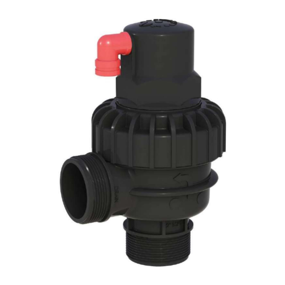
DYNAMIC COMBINATION AIR VALVE
MODEL D-070-P
The following is a step by step narrated description of the A.R.I. D-070-P Dynamic Combination Air Valve
installation, operation and maintenance processes.
The D-070-P Combination Dynamic Air Valve is a unique valve, operating without a float and utilizing the
rolling diaphragm principle.
The D-070-P air valve is designed for water systems that operate within the pressure and temperature
framework of the model's specifications table. Please consult A.R.I. for products designed for other
wastewater or hazardous liquids systems.
Advertisement
Table of Contents

Related Manuals for A.R.I. D-070-P


Summary of Contents for A.R.I. D-070-P
- Page 1 DYNAMIC COMBINATION AIR VALVE MODEL D-070-P The following is a step by step narrated description of the A.R.I. D-070-P Dynamic Combination Air Valve installation, operation and maintenance processes. The D-070-P Combination Dynamic Air Valve is a unique valve, operating without a float and utilizing the rolling diaphragm principle.
-
Page 2: Table Of Contents
IOM D-070-P TABLE OF CONTENTS 1. SAFETY INSTRUCTIONS ............................. 3 2. INSTALLATION ..............................6 3. OPERATION ..............................9 3. TROUBLE SHOOTING ............................9 5. PERIODIC MAINTENANCE ..........................10 5.1. Preparation ............................10 5.2. Removing the Pilot ..........................11 5.3. Maintenance of the Pilot ........................12 5.4. -
Page 3: Safety Instructions
IOM D-070-P 1. SAFETY INSTRUCTIONS General 1. A.R.I. products always operate as components in a larger system. It is essential for the system designers, installers, operators and maintenance personnel to comply with all the relevant safety standards. 2. Installation, operation or maintenance of the product should be done only by qualified workers, technicians... - Page 4 IOM D-070-P Installation 1. Install the product according to the detailed Installation Instructions provided with it by A.R.I. and according to the description given in this manual. 2. The user should install a manual Isolation Valve under the product's inlet port.
- Page 5 IOM D-070-P Before returning to regular operation 1. Re-assemble any protection covers or protection mechanisms removed during service or maintenance operations. 2. Make sure that all the tools, ladders, lifting devices, etc. used during the maintenance procedures are taken away from the product area and stored.
-
Page 6: Installation
IOM D-070-P 2. INSTALLATION Important: Before performing any work on the air valve make sure that all workers on site are familiar with the safety instructions and the relevant local and general safety instructions and work regulations. 2.1. Installation Recommendations Single Air Valve on an Isolating Valve at 45°... - Page 7 IOM D-070-P 2.2. Conventions and Measurements This paragraph presents and explains the terms and measurements used for the Installation process. Isolation Valve D = Diameter of pipeline d = diameter of riser H = Height of riser on the pipeline (Measured from crown of pipeline) •...
- Page 8 3. Install an isolating valve below the air valve, connected by a riser to the crown of the pipe. 4. The D-070-P Dynamic Combination Air Valve should be installed vertically on a riser on the crown of the pipeline. 5. Mount the air valve carefully on the rubber gaskets of the isolating valve.
-
Page 9: Operation
IOM D-070-P 3. OPERATION When the system is charged and the pipeline begins to fill with water, air flows in the pipeline and enters into the dynamic air valve, raising the rolling diaphragm sealing assembly to the open position. Air is then discharged, mainly through the large orifice as well as small amounts of air released through the pilot orifice. -
Page 10: Periodic Maintenance
IOM D-070-P 5. PERIODIC MAINTENANCE Please note that the periodic maintenance of the air valve is an integral part of the proper pipeline maintenance regime; it should be maintained at least once a year in accordance with the quality and composition of the fluid in the system. -
Page 11: Removing The Pilot
IOM D-070-P 5.2. Removing the Pilot • Unscrew and remove the Pilot Body [1], [2] 5.2.1. Cleaning of the Air Valve • Thoroughly wash and clean the air valve components under clean running water to remove all grime; Pay special attention to the internal parts. -
Page 12: Maintenance Of The Pilot
IOM D-070-P 5.3. Maintenance of the Pilot • Hold the Pilot Body, turn it to the side. Remove the Clamping Stem [1] and the Float [2] together with the Rolling Seal [3]. • Thoroughly but gently wash and clean all the components under clean running water. Pay attention to the sealing area inside... - Page 13 IOM D-070-P • Visually check the condition of the Rolling Seal [1]. If any cracks or tears are found, remove it from the Float [2] and replace it. • When required, replace the seal by inserting a new Rolling Seal into its designated groove. Please note: side [1] of the groove is slightly wider than the other [2];...
- Page 14 IOM D-070-P • Dip the head end of the Rolling Seal into the liquid soap solution [1] • Reassemble the Pilot by inserting the loose end of the Rolling Seal into its designated groove in the Pilot Body [2]; making sure...
- Page 15 IOM D-070-P • Insert the Float halfway into the Pilot Body [1], insert the Clamping Stem into the Rolling Seal groove of the Pilot Body; make sure that it is inserted in the direction of the arrow [2]. Push the Float and the Clamping Stem together downwards into the Pilot Body until they are locked [3].
-
Page 16: Maintaining The Dynamic Valve Body
IOM D-070-P 5.4. Maintaining the Dynamic Valve Body • Unscrew and remove the Pilot Body [1], [2] • Unscrew and remove the Locking Ring [1], [2]... - Page 17 IOM D-070-P • Remove the Rolling Diaphragm Sealing Assembly from the Body [1], [2]. Thoroughly but gently wash and clean all the components under clean running water, remove coarse grime and accumulated scale. Pay attention to the sealing area inside the Body [3].
-
Page 18: Assembly And Testing For Leaks
IOM D-070-P • Separate the Supporting Ring from the Rolling Diaphragm Sealing [1], [2]. • Fold backwards the rubber part of the Rolling Diaphragm Sealing [1] and check for any cracks and tears [2]. Replace the entire Rolling Diaphragm Sealing Assembly if any damage is detected. Do not open screws of the assembly under any circumstances! 5.5 Assembly and Testing for Leaks... -
Page 19: Assembly Bom Table And Drawing
IOM D-070-P 6. ASSEMBLY BOM TABLE AND DRAWING No. Part name QTY. Discharge Elbow Pilot Body O-ring Clamping Stem Rolling Seal Pilot Float Assy. Locking Ring Adaptor Rolling Diaphragm Sealing Assy. Supporting Ring Body... -
Page 20: Limited Warranty
IOM D-070-P 7. A.R.I. LIMITED WARRANTY A.R.I. Standard International Warranty A.R.I. manufactured products are guaranteed to be free from defect in material and/or workmanship and to perform as advertised when properly installed, used and maintained in accordance with current instructions, written or verbal.
Need help?
Do you have a question about the D-070-P and is the answer not in the manual?
Questions and answers