Table of Contents
Advertisement
Quick Links
D-46.IOM.ENG02-20.12.21
Installation, Operation & Maintenance
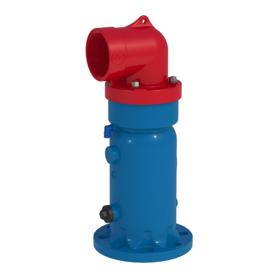
COMBINATION AIR VALVE
MODEL D-46 PRO 2", 3", 4", 6"
The following is a step-by-step narrated description of the A.R.I. D-46 PRO combination air valve
installation, operation and maintenance processes.
The D-46 air valve has the features of both an Automatic Air Release valve and an Air & Vacuum valve.
The Air Release component is designed to automatically release small pockets of air to the atmosphere as
they accumulate along a pipeline or piping system when it is full and operating under pressure. The Air &
Vacuum component is designed to automatically discharge or admit large volumes of air during the filling
or draining of a pipeline or piping system. This valve will open to relieve negative pressures whenever
water column separation occurs.
Advertisement
Table of Contents

Related Manuals for A.R.I. D-46 PRO 2


Summary of Contents for A.R.I. D-46 PRO 2
- Page 1 D-46.IOM.ENG02-20.12.21 Installation, Operation & Maintenance COMBINATION AIR VALVE MODEL D-46 PRO 2”, 3”, 4”, 6” The following is a step-by-step narrated description of the A.R.I. D-46 PRO combination air valve installation, operation and maintenance processes. The D-46 air valve has the features of both an Automatic Air Release valve and an Air & Vacuum valve.
-
Page 2: Table Of Contents
TABLE OF CONTENTS 1. SAFETY INSTRUCTIONS ..........................4 Safety Instructions - General ........................... 4 Safety Instructions - Handling ..........................4 Safety Instructions - Installation ..........................4 Safety Instructions - Commissioning and Operation .................... 5 Safety Instructions - Maintenance .......................... 5 Safety Instructions - Before returning to regular operation .................. - Page 3 Disclaimer This document is an Installation, Operation and Maintenance (IOM) manual for A.R.I. Flow Control Accessories Ltd. (A.R.I.) products. The information enclosed herein contains restricted, privileged, proprietary and confidential information, intended only for usage by authorized A.R.I. technicians. If you are not a qualified technician, you must not take any action in reliance upon this document, unless otherwise permitted in writing by A.R.I.
-
Page 4: Safety Instructions
1. SAFETY INSTRUCTIONS Safety Instructions - General A.R.I. products always operate as components in a larger system. It is essential for the system designers, installers, operators and maintenance personnel to comply with all the relevant safety standards. Installation, operation or maintenance of the product should be done only by qualified workers, technicians and/or contractors using only good engineering practices, complying with and observing all conventional safety instructions in order to minimize risk and/or danger and/or hazard to workers, the public or to property in the vicinity in accordance with all relevant local standards. -
Page 5: Safety Instructions - Commissioning And Operation
Safety Instructions - Commissioning and Operation Read carefully the operation instructions prior to any attempt to operate the product. Observe the safety stickers on the product and never perform any operation contradicting the instructions given. In order to achieve maximum performance and smooth operation of the product, it is crucial to perform the startup and first operation procedures exactly as described in this manual. -
Page 6: Installation
2. INSTALLATION Important: Before performing any work on the air valve make sure that all workers on site are familiar with the safety instructions and the relevant local and general safety instructions and work regulations. 2.1. Installation Recommendations Single Air Valve on an Isolating Valve at 45° to Air Valve outlet Two Air Valves on a shared Isolating Valve. -
Page 7: Conventions And Measurements
2.2. Conventions and Measurements This paragraph presents and explains the terms and measurements used for the Installation process. Isolation D = Diameter of pipeline Valve d = diameter of riser H = Height of riser on the pipeline (Measured from crown of pipeline) •... -
Page 8: Installation Instructions
2.3. Installation Instructions 1. Flush the system before installing the air valve to avoid any debris or sharp objects getting into the air valve. 2. Carefully remove the air valve from the shipping package. Unload all air valves carefully to a sturdy level surface taking care not to drop them. -
Page 9: Operation
3. OPERATION The Air & Vacuum component, with the large orifice, discharges air at high flow rates during the filling of the system, and admits air into the system, at high flow rates, during system’s drainage and at water column separation. -
Page 10: Periodic Maintenance
4. PERIODIC MAINTENANCE Please note that the periodic maintenance of the air valve is an integral part of the proper pipeline maintenance regime; it should be maintained at least once a year in accordance with the quality and composition of the fluid in the system. Important: Before performing any work on the air valve, make sure that all workers on site are familiar with the safety instructions as appear chapter of this document and with all the relevant local and general safety instructions, standards and work regulations. -
Page 11: Maintaining The Metal Air Valve (2" Model - Metallic)
4.2. Maintaining the Metal Air valve (2” model - Metallic) Refer to the BOM drawing on the next page. 1. Shut the isolating valve below the air valve. 2. Manually remove the Snap Ring (# 10) from the base of the air valve Body (# 5). 3. -
Page 12: Assembly Bom Table And Drawing - D-46 2
4.3. ASSEMBLY BOM TABLE AND DRAWING – D-46 2” Discharge Elbow Nuts Seal Non-Slam Component (Optional) Drain Outlet Body Threaded Rods Pressure Release Plug Air & Vacuum Seal Air Release / Air & Vacuum Assembly Float Seat Snap Ring... -
Page 13: Maintaining The Air Valve (2" Model - Polymeric)
4.4. Maintaining the Air valve (2” model - Polymeric) Refer to the BOM drawing on the next page. 1. Shut the isolating valve below the air valve. 2. Remove the 2” D-46 Air Valve from the isolating valve. 3. Unscrew the Discharge Elbow (# 1). 4. -
Page 14: Assembly Bom Table And Drawing - D-46 2" Polymeric
4.5. ASSEMBLY BOM TABLE AND DRAWING – D-46 2” Polymeric Discharge Elbow Non-Slam Component (Optional) Air & Vacuum Seal Air Release / Air & Vacuum Assembly O-ring Body O-ring Flange... -
Page 15: Maintaining The Air Valve (3", 4", 6" Model)
4.6. Maintaining the Air valve (3”, 4”, 6” model) Refer to the BOM drawing on the next pages. 1. Shut the isolating valve below the air valve. 2. Manually remove the Snap Ring (# 11) from the base of the air valve Body (# 5). 3. -
Page 16: Assembly Bom Table And Drawing - D-46 3" & 4
4.7. ASSEMBLY BOM TABLE AND DRAWING – D-46 3” & 4” Discharge Elbow Nuts Seal Non-Slam Component (Optional) Drain Outlet Body Threaded Rods Pressure Release Plug Air Release Assembly Air & Vacuum Seal Air & Vacuum Float Float Seat Snap Ring... -
Page 17: Assembly Bom Table And Drawing - D-46 6
4.8. ASSEMBLY BOM TABLE AND DRAWING – D-46 6” Discharge Elbow Nuts Seal Non-Slam Component Drain Outlet Body Threaded Rods Pressure Release Plug Air Release Assembly Air & Vacuum Seal Air & Vacuum Float Float Seat Snap Ring Flange Assembly (optional) -
Page 18: Troubleshooting
2. TROUBLESHOOTING Symptom Possible Causes Remedy Debris or scale buildup on the Rolling Perform periodic Leakage from the valve’s outlet Seal. maintenance Debris caught between the Air & Vacuum Seal and the Body. Torn or cracked Rolling Seal and/or Air & Vacuum Seal Air valve was hit or mishandled Unscrew and replace. -
Page 19: Limited Warranty
3. A.R.I. LIMITED WARRANTY A.R.I. Standard International Warranty A.R.I. manufactured products are guaranteed to be free from defect in material and/or workmanship and to perform as advertised when properly installed, used and maintained in accordance with current instructions, written or verbal. Should any item prove defective within the time period set forth for that item(s), but in any case not later than within 12 (Twelve) months of that product having left A.R.I.’s premises, and subject to receipt by A.R.I.
Need help?
Do you have a question about the D-46 PRO 2 and is the answer not in the manual?
Questions and answers