Advertisement
Quick Links
D26.3.IOM.US02
Installation, Operation & Maintenance
COMBINATION AIR VALVE
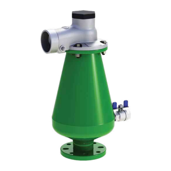
MODEL D-26 3"
The following is a step by step narrated description of the A.R.I. D-26 industrial combination air valve
installation, operation and maintenance processes.
The D-26 air valve is designed for systems that operate within the pressure and temperature framework
of the model's specifications table. Please consult A.R.I. for products designed for other hazardous liquids
systems.
Advertisement

Subscribe to Our Youtube Channel
Related Manuals for A.R.I. D-26


Summary of Contents for A.R.I. D-26
- Page 1 COMBINATION AIR VALVE MODEL D-26 3" The following is a step by step narrated description of the A.R.I. D-26 industrial combination air valve installation, operation and maintenance processes. The D-26 air valve is designed for systems that operate within the pressure and temperature framework of the model's specifications table.
-
Page 2: Table Of Contents
IOM D-26 3 TABLE OF CONTENTS 1. Safety Instructions ......................Page 3 2. Installation ........................Page 6 3. Operation ........................Page 8 4. Troubleshooting ......................Page 8 5. Periodic Maintenance ....................Page 9 6. Assembly BOM Table and Drawing ................ Page 21 7. -
Page 3: Safety Instructions
IOM D-26 3 1. SAFETY INSTRUCTIONS General A.R.I. products always operate as components in a larger system. It is essential for the system designers, installers, operators and maintenance personnel to comply with all the relevant safety standards. Installation, operation or maintenance of the product should be done only by qualified workers, technicians and/or... - Page 4 IOM D-26 3 Installation Install the product according to the detailed Installation Instructions provided with it by A.R.I. and according to the description given in this manual. The user should install a manual Isolation Valve under the product's inlet port.
- Page 5 IOM D-26 3 Before returning to regular operation Re-assemble any protection covers or protection mechanisms removed during service or maintenance operations. Make sure that all the tools, ladders, lifting devices, etc. used during the maintenance procedures are taken away from the product area and stored.
-
Page 6: Installation
IOM D-26 3 2. INSTALLATION Important: Before performing any work on the air valve make sure that all workers on site are familiar with the safety instructions and the relevant local and general safety instructions and work regulations. 2.1. Installation Recommendations Single Air Valve on an Isolating Valve at 45°... - Page 7 IOM D-26 3 2.2. Conventions and Measurements Isolation valve This paragraph presents and explains the terms and measurements used for the Installation process. D = Diameter of pipeline d = diameter of riser H = Height of riser on the pipeline (measured from crown of pipeline) •...
-
Page 8: Operation
IOM D-26 3 3. OPERATION When the system is charged and the pipeline begins to fill, the water flowing in the pipeline enters into the combination air valve, raising the air/ vacuum and air release floats to their sealing position. -
Page 9: Periodic Maintenance
IOM D-26 3 5. PERIODIC MAINTENANCE Please note that the periodic maintenance of the air valve is an integral part of the proper pipeline maintenance regime; it should be maintained at least once a year in accordance with the quality and composition of the fluid in the system. - Page 10 IOM D-26 3 5.2.2 Removal of the Sealing Assembly • Using the two 19mm combination spanners, open and remove the four Bolts, Nuts and Washers [1] • Store the four Bolts, Nuts and Washers in an accessible area [2] • Lift and extract the Cover assembly from the valve Body [3] 5.2.3.
- Page 11 IOM D-26 3 5.2.4. Assembly and Testing for Leaks • Insert the Cover & Float Assembly into the main valve Body [1]. • Insert the four Bolts, Nuts and Washers [2] . Using the two 19mm combination spanners, tighten using the crossover method [3].
- Page 12 IOM D-26 3 5.3. Second Stage Maintenance Perform if the first stage doesn't solve the leak, if one of the seals or inner parts need replacement or for periodic maintenance to thoroughly clean the valve. 5.3.1. Releasing Pressure • Shut the isolating valve located on the riser under the air valve •...
- Page 13 IOM D-26 3 2- Remove the Spray Guard • Pull open the Spray Guard by the slit and remove it from the assembly rod [1] [2] 3- Remove the Seal & Float Assembly from the Cover • Use the 4mm Allen key and 8mm spanner to unscrew the Domed Nut [1] •...
- Page 14 IOM D-26 3 5.3.3. Maintenance 1- Cleaning Wash and clean all disassembled parts, including the Float and Seal Assembly, Spray Guard, Body and Cover under clean running water to remove all dirt and grime. 2- Replacing the Automatic Air Release and Air & Vacuum (Kinetic) Seals 2.1 Opening the Seal Assembly...
- Page 15 IOM D-26 3 2.2 Replacing the Automatic Air Release Rolling Seal • To replace the Air Release Rolling Seal [1] pull the seal out of the slots from both ends and discard [2] [3] • Dip both ends of the new replacement Rolling Seal in the liquid soap [4] •...
- Page 16 IOM D-26 3...
- Page 17 IOM D-26 3 2.3 Replacing the Air & Vacuum (Kinetic) Seal • Hold the Air & Vacuum Seal [1] and pull it off the lower section of the Seal housing [2], [3] • Place the new Seal on the Seal housing [4] and press down...
- Page 18 IOM D-26 3 2.4 Closing the Seal Assembly • Align the 4 holes of the top and bottom section of the Seal Assembly housing [1] and close one section against the other [2] • Insert the 4 screws into the Seal Assembly housing [3] and...
- Page 19 IOM D-26 3 5.3.4. Assembly 1- Cover Assembly • Examine the Cover O-ring for cracks or tears [1]. Replace, if necessary. •. Insert the Disk Arm Assembly, together with the attached Seal and Float Assembly into the bottom opening of the Cover [2], [3] •...
- Page 20 IOM D-26 3 2- Insert the Cover and Seal & Float Assembly • Pull open the Spray Guard by the slit and slide it over the assembly rod [1] [2] • Lift and insert the Float and Seal Assembly into the Body [3] •...
-
Page 21: Assembly Bom Table And Drawing
IOM D-26 3 6. ASSEMBLY BOM TABLE AND DRAWING 6. ASSEMBLY BOM TABLE AND DRAWING No. Part name QTY. Threaded Plug Cover Bolt Washer Bushing Domed Nut Disk Arm Air & Vacuum Seal Seat Air & Vacuum Seal Air Release Seal Air Release Seal Seat Air &... -
Page 22: Ordering Replacement Parts
IOM D-26 3 7. Ordering Replacement Parts Manual No. D-263.IOM.ENG01 Size Cat. No. BOM No. Part Quantity Threaded Plug [3 - 6] Bolt, Washer, Bushing, Nut Assy. Air & Vacuum Seal [10] Air Release Seal [13] Screws [14] Spray Guard [15] Domed Nut &... -
Page 23: Limited Warranty
A.R.I. LIMITED WARRANTY A.R.I. Standard International Warranty A.R.I. manufactured products are guaranteed to be free from defect in material and/or workmanship and to perform as advertised when properly installed, used and maintained in accordance with current instructions, written or verbal. Should any item prove defective within the time period set forth for that item(s), but in any case not later than within 5 (five) years of that product having left A.R.I.
Need help?
Do you have a question about the D-26 and is the answer not in the manual?
Questions and answers