Table of Contents
Advertisement
Quick Links
D020.ARISENSE.IOM.ENG02
Installation, Operation & Maintenance
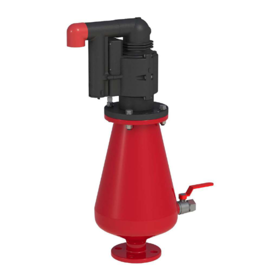
COMBINATION AIR VALVE
MODEL D-020 ARISENSE
The following is a step-by-step narrated description of the A.R.I. D-020 ARISENSE industrial combination air
valve installation, operation and maintenance processes.
The D-020 ARISENSE air valve is designed for systems that operate within the pressure and temperature
framework of the model's specifications table. Please consult A.R.I. for products designed for other
hazardous liquids systems.
Advertisement
Table of Contents

Related Manuals for A.R.I. D-020 ARISENSE


Summary of Contents for A.R.I. D-020 ARISENSE
- Page 1 The following is a step-by-step narrated description of the A.R.I. D-020 ARISENSE industrial combination air valve installation, operation and maintenance processes. The D-020 ARISENSE air valve is designed for systems that operate within the pressure and temperature framework of the model's specifications table. Please consult A.R.I. for products designed for other...
-
Page 2: Table Of Contents
IOM D-020 ARISENSE TABLE OF CONTENTS 1. SAFETY INSTRUCTIONS ............................. 3 2. INSTALLATION ..............................6 3. INITIALIZING THE ARISENSE SYSTEM........................ 9 4. INITIAL STARTUP OF THE ARISENSE SYSTEM ....................12 5. OPERATION ..............................35 6. TROUBLESHOOTING ............................35 7. REPLACING THE ARISENSE BATTERY ......................36 8. -
Page 3: Safety Instructions
IOM D-020 ARISENSE 1. SAFETY INSTRUCTIONS General 1. A.R.I. products always operate as components in a larger system. It is essential for the system designers, installers, operators and maintenance personnel to comply with all the relevant safety standards. 2. Installation, operation or maintenance of the product should be done only by qualified workers, technicians and/or... - Page 4 IOM D-020 ARISENSE Installation 1. Install the product according to the detailed Installation Instructions provided with it by A.R.I. and according to the description given in this manual. 2. The user should install a manual Isolation Valve under the product's inlet port.
- Page 5 IOM D-020 ARISENSE Before returning to regular operation 1. Re-assemble any protection covers or protection mechanisms removed during service or maintenance operations. 2. Make sure that all the tools, ladders, lifting devices, etc. used during the maintenance procedures are taken away from the product area and stored.
-
Page 6: Installation
IOM D-020 ARISENSE 2. INSTALLATION Important: Before performing any work on the air valve make sure that all workers on site are familiar with the safety instructions and the relevant local and general safety instructions and work regulations. 2.1. Installation Recommendations Single Air Valve on an Isolating Valve at 45°... - Page 7 IOM D-020 ARISENSE 2.2. Conventions and Measurements This paragraph presents and explains the terms and measurements used for the Installation process. D = Diameter of pipeline d = diameter of riser H = Height of riser on the pipeline (Measured from crown of pipeline)
- Page 8 IOM D-020 ARISENSE 2.3. Installation Instructions Flush the system before installing the air valve to avoid any debris or sharp objects getting into the air valve. 2. Carefully remove the air valve from the shipping package. Unload all air valves carefully to a sturdy level surface taking care not to drop them.
-
Page 9: Initializing The Arisense System
IOM D-020 ARISENSE 3. INITIALIZING THE ARISENSE SYSTEM Once the air valve is physically installed, the Arisense system should be prepared for operation, please follow the following steps: Leak Detector Case from the air valve before Please note: In cramped installation spaces you may disconnect the physically installing the valve on the pipeline. - Page 10 IOM D-020 ARISENSE Using the Flat screwdriver [1], remove the ARISENSE black Air Release Outlet [2], [3]. Using a screwdriver unscrew the four bolts of the battery compartment cover [2] and remove the cover [3]. 3.3. Insert the SIM card Insert the SIM card to its designated socket at the lower part of the battery compartment [4] &...
- Page 11 IOM D-020 ARISENSE 3.4. Connect the battery Connect the battery’s orange female connector [6] to the Arisense white male connector [7]. Reassemble the battery compartment cover [8] and the red outlet elbow. The Arisense is initialized and ready to be configured and connected to the communication network.
-
Page 12: Initial Startup Of The Arisense System
IOM D-020 ARISENSE 4. INITIAL STARTUP OF THE ARISENSE SYSTEM Once the air valve is physically installed and the Arisense system is initialized, it should be connected to the communication network. This process is done via a special Smartphone Applications named Arisense. - Page 13 IOM D-020 ARISENSE 4.1 The Bluetooth (BT) application: Download and install the BT Arisense application by scanning this QR code with your Smartphone: Download the Application file, install it on your Smartphone and make sure that the application has all the required permissions.
- Page 14 IOM D-020 ARISENSE 2. Connecting and using the Arisense Bluetooth (BT) communication: User Selection - On the Welcome Screen, choose between 2 versions of the app: Basic and EXPERT. The following description is for a BASIC USER type. Basic User Picture 3 - User Type Selection Screen ...
- Page 15 IOM D-020 ARISENSE Very Important: o Once the password is set, it will be required at every entry to the application. o Once set, the password cannot be changed again! On the main screen, select the first button (IDENTIFY).
- Page 16 IOM D-020 ARISENSE Once the CONNECT button is pressed, move a magnet near the valve at the designated location at the bottom of the unit. Picture 7 - Magnet designated location Note: The Air Valve model is for illustration only ...
- Page 17 IOM D-020 ARISENSE A Connecting message appears on screen: Picture 9 – “Connecting” message Wait until the ID number of the unit you are connecting to appear on screen and the Green LED on the upper left side of the screen is turned on. Your Smartphone application is connected now to the Arisense air valve.
- Page 18 IOM D-020 ARISENSE Unit Information – SETTINGS Screen of the Arisense Bluetooth application (BT) Clicking 'SETTINGS' will take you to a screen where information about the unit is displayed, such as: valve type, software versions, regional clock, etc. You can change the valve type by clicking on the image and selecting from the list of images that open.
- Page 19 IOM D-020 ARISENSE The Sensor Test Status – TEST To check the unit sensors status, click on 'TEST'. On the screen that opens you can see the status of all the unit sensors by a LED display. (Green = okay, no alert. Red = Alert activated. Shut-off = communication with the unit is disconnected and needs to be reconnected).
- Page 20 IOM D-020 ARISENSE In the 'Location Description' window, enter the installation location description in a few words. Make sure that the location coordinates of the installation appear. You can take a photo of the installation by clicking 'TAKE A PICTURE'.
- Page 21 IOM D-020 ARISENSE Expert User In addition to the basic functions available to the basic user, there are several additional actions for use by the advanced user. Picture 16 - Main Screen (Advanced User) Communication Testing – DETECT ...
- Page 22 IOM D-020 ARISENSE VII. Expert User - SETTINGS Screen of the Arisense Bluetooth application (BT) The 'SETTINGS' screen has other options, not available to the basic user, such as: Software Update. Picture 18 - Setting Screen (Advanced User) VIII.
- Page 23 IOM D-020 ARISENSE 4.2 The Technician Unit (RT) application: Download and install the BT Arisense application by scanning this QR code with your Smartphone: Download the Application file, install it on your Smartphone and make sure that the application has all the required permissions.
- Page 24 IOM D-020 ARISENSE The Welcome screen appears Picture 3 – Welcome screen General Note: At any stage of the application operation, you can return to the main screen by clicking on the ARISENSE icon at the top of the screen.
- Page 25 IOM D-020 ARISENSE Setting Password - Once the User Type is selected, the set password screen appears. Set your password; it should contain four characters: Letters, Numbers or a Mixture of letters and numbers. Picture 5 – Set Password Screen Very Important: o Once the password is set, it will be required at every entry to the application.
- Page 26 IOM D-020 ARISENSE To connect Bluetooth communication from your mobile device to the technician unit, select the first button - 'CONNECT TO RT'. Picture 7 - Connection screen From the list of open connected devices to your device, select IWEPTool with the Unit Code as shown on the unit (see Picture 1).
- Page 27 IOM D-020 ARISENSE Picture 9 - Unit search At this point, move a magnet near the valve at the designated location at the bottom of the unit until a confirmation message is received on the screen. The message will list the ID number of the unit you are connecting to.
- Page 28 IOM D-020 ARISENSE Wait until a confirmation message is received on the screen. The message will list the ID number of the unit you are connecting to. Select the Identified unit. Picture 11 - Connected unit message Confirm the message.
- Page 29 IOM D-020 ARISENSE Return to the main screen. Note: Upon completion of working with the app, you must log out by clicking the "Back" button on your cell phone and then clicking OK on the message that appears. Picture 13 - The EP connection disconnect screen at work completion Unit Information –...
- Page 30 IOM D-020 ARISENSE III. Sensor Test Status – TEST To check the unit sensors status, click on 'TEST'. On the screen that opens you can see the status of all the unit sensors by a LED display. (Green = okay, no alert. Red = Alert activated. Shut-off = communication with the unit is disconnected and needs to be reconnected).
- Page 31 IOM D-020 ARISENSE In the 'Location Description' window, enter the installation location description in a few words. Make sure that the location coordinates of the installation appear. You can take a photo of the installation by clicking 'TAKE A PICTURE'.
- Page 32 IOM D-020 ARISENSE Expert User Once an Expert user is selected the password setting screen appears: Setting Password - Once the User Type is selected, the set password screen appears. Set your password; it should contain four characters: Letters, Numbers or a Mixture of letters and numbers.
- Page 33 IOM D-020 ARISENSE In addition to the basic functions available to the basic user, there are several additional actions for use by the expert user. Picture 19 - Main Screen (Expert User) Communication Testing – DETECT Clicking 'DETECT' will trigger a communication check.
- Page 34 IOM D-020 ARISENSE Expert User - Unit Information – SETTINGS The 'SETTINGS' screen has other options, not available to the basic user, such as: Software Update. XII. Expert User - Unit Registration – REGISTER In the Partner Unit registration, you can choose between automatic registration and registration for a specific master unit of your choice, and you also can force registration or removal even if there is no transmission at the moment (goes into effect as soon as there is transmission).
-
Page 35: Operation
IOM D-020 ARISENSE 5. OPERATION When the system is charged and the pipeline begins to fill, the water flowing in the pipeline enters into the combination air valve, raising the air/ vacuum and air release floats to their sealing position. -
Page 36: Replacing The Arisense Battery
IOM D-020 ARISENSE 7. REPLACING THE ARISENSE BATTERY When needed replace the Arisense battery with a new battery acquired from A.R.I. Open the battery compartment as described in section 3.2 of this document. Disconnect the battery’s orange female connector [1] from the Arisense white male connector [2] and pull out the used battery [3]. -
Page 37: Periodic Maintenance
Chapter 1 of this document and with all the relevant local and general safety instructions, standards and work regulations. Please note that maintaining the D-020 ARISENSE product consists of two separated procedures: Maintaining the Air Valve Component and maintaining the Arisense component. - Page 38 IOM D-020 ARISENSE 8.2. Servicing the Arisense component Required tools and materials: • Flat tip screwdriver • Phillips head screwdriver • 8mm combination spanner • 6 mm Allen key • Plastic head hammer • Small bowl with kitchen type liquid soap 8.2.1.
- Page 39 IOM D-020 ARISENSE Using the Flat screwdriver [1], remove the ARISENSE black Air Release Outlet [2], [3]. 8.2.2. Removing the Operating Valve Body Unscrew and remove the Operating Valve Body [1], [2].
- Page 40 IOM D-020 ARISENSE 8.2.3. Removing the Float Hold the Operating Valve Body, turn it to the side [1] and remove the Clamping Stem [2] and the Float [3] (together with the Rolling Seal.
- Page 41 IOM D-020 ARISENSE 8.2.4. Cleaning and inspecting the components Thoroughly but gently wash and clean all the components under clean running water. Pay attention to the sealing area inside the Body. Visually check the condition of the Rolling Seal [1] & [2]. If any cracks or tears are found remove it from the Float and replace it.
- Page 42 IOM D-020 ARISENSE Pay attention to the correct position and direction and insert the tail end of the Rolling Seal Assembly into the groove on the Float [5]. Gently pull the Rolling Seal Assembly until it is partially inserted into the Float grove. Use the 4.5mm Roll Pin Punch to push the Rolling Seal Assembly to the middle of the Float [6] and align the middle of the Rolling Seal Assembly tail with the midline of the Float [7].
- Page 43 IOM D-020 ARISENSE 8.2.5. Reassembling the Operating Valve Reassemble the Operating Valve by inserting the loose end of the Rolling Seal into its designated groove in the Body, make sure that the insertion direction and the end of the seal are as depicted on pictures [1] and [2].
- Page 44 IOM D-020 ARISENSE 8.2.6. Cleaning the ARISENSE black Air Release Outlet Remove the lower plug of the ARISENSE black air release outlet [1] and [2] then thoroughly but gently wash and clean the components under clean running water. 8.2.7. Reassembling the ARISENSE Unit...
- Page 45 IOM D-020 ARISENSE 8.3. Servicing the D-020 Arisense Air Valve 8.3.1. Required tools and materials: • 2 units - 19mm combination spanner • 4.5mm roll pin punch • Small bowl with kitchen type liquid soap 8.3.2. Releasing the pressure • Shut the isolating valve located on the riser under the air valve •...
- Page 46 IOM D-020 ARISENSE 8.3.3. Removing the Cover Assembly • Using the two 19mm combination spanners, open and remove the four Bolts, Nuts and Washers [1]. • Store the four Bolts, Nuts and Washers in an accessible area [2] • Lift and extract the Cover assembly from the valve Body [1], [2], [3]...
- Page 47 IOM D-020 ARISENSE • Place the entire assembly on a clean, flat surface 8.3.4. Cleaning Thoroughly wash and clean the inside of the Air Valve Body, and the float assembly under clean running water to remove all grime, clean and check the body’s flange O-ring.
-
Page 48: Assembly Bom Table And Drawing
IOM D-020 ARISENSE 9. ASSEMBLY BOM TABLE AND DRAWING Discharge Elbow Body Leak Detector Case Screws Leak Detector Cover Rolling Seal Assembly Clamping Stem Float Screws Battery Cover Battery Cover Seal Battery O-Ring Electronics Case Ring Float Ring Float Connector... - Page 49 IOM D-020 ARISENSE O-Ring Cover Domed Nut Stopper Spring Float Assembly O-Ring Bolts Body...
-
Page 50: Annex A. External Antenna Installation Procedure
IOM D-020 ARISENSE 10. ANNEX A. EXTERNAL ANTENNA INSTALLATION PROCEDURE The following is a general description of the Arisense External Antenna installation procedure. Please note: The actual installation process depends on the specific layout of the installation site and on the operation conditions. - Page 51 IOM D-020 ARISENSE 10.4 Connect the antenna’s cable to the air valve’s connector; fasten the thread with hand power only [1]. 10.5 Attach the conduit tube to the air valve’s body, heat and shrink the coupler sleeve with a heat gun [1], [2], [3].
- Page 52 IOM D-020 ARISENSE 10.7 Once the valve’s side of the connection is secured insert the SIM card and the battery to the Arisense unit and connect the Leak Detector Case and the Discharge Elbow [1]; for specific instructions please refer to the Arisense installation IOM.
- Page 53 IOM D-020 ARISENSE 10.10 Important notes: a. If the antenna cable is too long, do not cut it; roll and secure it with suitable brackets to the manhole wall. b. If possible, install the antenna outside of the manhole, in such case make sure that the antenna is installed in a safe and protected place.
Need help?
Do you have a question about the D-020 ARISENSE and is the answer not in the manual?
Questions and answers