Advertisement
Quick Links
D025.IOM.ENG03
Installation, Operation & Maintenance
COMBINATION AIR VALVE
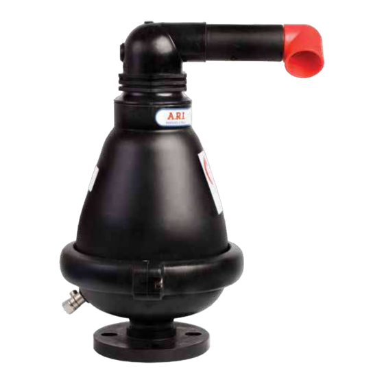
MODEL D-025
The following is a step by step narrated description of the A.R.I. D-025 industrial combination air valve
installation, operation and maintenance processes.
The D-025 air valve is designed for systems that operate within the pressure and temperature framework
of the model's specifications table. Please consult A.R.I. for products designed for other hazardous liquids
systems.
Advertisement

Related Manuals for A.R.I. D-025


Summary of Contents for A.R.I. D-025
- Page 1 COMBINATION AIR VALVE MODEL D-025 The following is a step by step narrated description of the A.R.I. D-025 industrial combination air valve installation, operation and maintenance processes. The D-025 air valve is designed for systems that operate within the pressure and temperature framework of the model's specifications table.
-
Page 2: Table Of Contents
IOM D-025 TABLE OF CONTENTS 1. Safety Instructions ......................Page 3 2. Installation ........................Page 6 3. Operation ........................Page 8 4. Troubleshooting ......................Page 8 5. Periodic Maintenance ....................Page 9 6. Assembly BOM Table and Drawing ................ Page 21 7. -
Page 3: Safety Instructions
IOM D-025 1. SAFETY INSTRUCTIONS General A.R.I. products always operate as components in a larger system. It is essential for the system designers, installers, operators and maintenance personnel to comply with all the relevant safety standards. Installation, operation or maintenance of the product should be done only by qualified workers, technicians and/or... - Page 4 IOM D-025 Installation Install the product according to the detailed Installation Instructions provided with it by A.R.I. and according to the description given in this manual. The user should install a manual Isolation Valve under the product's inlet port. In all installation sites, the user should enable good visibility and verify that the work and auxiliary equipment used are done in accordance with the relevant local authorized standards.
- Page 5 IOM D-025 Before returning to regular operation Re-assemble any protection covers or protection mechanisms removed during service or maintenance operations. Make sure that all the tools, ladders, lifting devices, etc. used during the maintenance procedures are taken away from the product area and stored.
-
Page 6: Installation
IOM D-025 2. INSTALLATION Important: Before performing any work on the air valve make sure that all workers on site are familiar with the safety instructions and the relevant local and general safety instructions and work regulations. 2.1. Installation Recommendations Single Air Valve on an Isolating Valve at 45°... - Page 7 IOM D-025 2.2. Conventions and Measurements This paragraph presents and explains the terms and measurements used for the Installation process. Isolation valve D = Diameter of pipeline d = diameter of riser H = Height of riser on the pipeline (measured from crown of pipeline) •...
-
Page 8: Operation
IOM D-025 3. OPERATION When the system is charged and the pipeline begins to fill, the water flowing in the pipeline enters into the combination air valve, raising the air/ vacuum and air release floats to their sealing position. During filling, air is discharged mainly through the air/ vacuum orifice as well as small amounts of air released through the air release orifice. -
Page 9: Periodic Maintenance
IOM D-025 5. PERIODIC MAINTENANCE Please note that the periodic maintenance of the air valve is an integral part of the proper pipeline maintenance regime; it should be maintained at least once a year in accordance with the quality and composition of the fluid in the system. - Page 10 IOM D-025 5.1.3 Remove the Air Valve Assembly • Turn the upper Body one full turn counterclockwise to loosen it from the Body [1] • With the plastic hammer, tap down on the upper part of the outlet elbow [2]...
- Page 11 IOM D-025 • Insert the Allen screwdriver into the Allen screw head and turn counterclockwise to open [1] • Remove Screw and Nut [2] • Pull out to remove the Clamp from the valve Body [3]...
- Page 12 IOM D-025 • Tap on the top of the Body to separate it from the Base [1] • Place the entire assembly on a clean, flat surface [2] 5.3. Maintenance 5.3.1. Disassembly and Cleaning • Thoroughly wash and clean the inside of the Body, the Float [1] and the Base [2] under clean running water to remove all grime.
- Page 13 IOM D-025 • Turn the upper Body counterclockwise to release, lift and separate it from the main Body [1], [2] • Place the entire assembly on a clean, flat surface [3]...
- Page 14 IOM D-025 • Grasp the Clamping Stem and pull out to remove it from the upper Body [1], [2], [3] • Pull out to remove the Float & Seal assembly from the upper Body [4], [5]...
- Page 15 IOM D-025 • Thoroughly wash and clean all removed components including the Float & Seal assembly, the Upper Body and the Clamping Stem under clean running water to remove all grime [1] • Important: During cleaning, pay special attention to the sealing area of the upper Body [2], the area around the O-ring in the top of the main Body [3].
- Page 16 IOM D-025 • Take a new Rolling Seal Assembly and dip the tail end into the liquid soap solution [1] • Pay attention to the correct position and direction [2]. • Insert the tail end of the Rolling Seal Assembly into the groove on the Float [2].
- Page 17 IOM D-025 • Check the integrity of the main body O-ring [1]. Remove and replace, if necessary [2]. 5.3.3 Assembly • Position the Cover & Float assembly at the edge of the table so the float can hang over the end of the table [1].
- Page 18 IOM D-025 • Take the Clamping Stem and insert it with smooth side up into the same groove, just behind the triangular end of the Rolling Seal [1] • Simultaneously push down on the Float and the Clamping Stem [2] till the end so they sit flush with the valve black Body [3].
- Page 19 IOM D-025 • Place the assembled main Body onto the Base and press down to insure the Body is aligned over the O-ring on the Base [1]. • With the aid of the plastic hammer, tap down on the top of the Body [2] until it sits flush with the Base and no gap between the...
- Page 20 IOM D-025 • Place the Clamp on the ridge between the Body and the Base [1]. • Insert the Screw and Nut into the Clamp [2], and tighten with the aid of the 6mm Allen screwdriver until tightly closed [3].
-
Page 21: Assembly Bom Table And Drawing
IOM D-025 6. ASSEMBLY BOM TABLE AND DRAWING 6. ASSEMBLY BOM TABLE AND DRAWING No. Part name QTY. Discharge Elbow Extension Body Clamping Stem Rolling Seal Assembly Float Connector O-ring Body Domed Nut Stopper Spring Float + Stem + Washer O-ring Clamp, Bolt &... -
Page 22: Ordering Replacement Parts
IOM D-025 7. Ordering Replacement Parts Manual No. D025.IOM.ENG01 Size Cat. No. BOM No. Part Quantity Discharge Elbow Extension Clamping Stem Rolling Seal Assembly Bolt, Nut & Washer Domed Nut Stopper [10] Spring [11] O-ring (Cover) [13] Float Assembly [1-6], [8-13] Complete Float, Seal &... -
Page 23: Limited Warranty
A.R.I. LIMITED WARRANTY A.R.I. Standard International Warranty A.R.I. manufactured products are guaranteed to be free from defect in material and/or workmanship and to perform as advertised when properly installed, used and maintained in accordance with current instructions, written or verbal. Should any item prove defective within the time period set forth for that item(s), but in any case not later than within 12 (Twelve) months of that product having left A.R.I.
Need help?
Do you have a question about the D-025 and is the answer not in the manual?
Questions and answers