Table of Contents
Advertisement
Quick Links
D26.IOM.ENG0
Installation, Operation & Maintenance
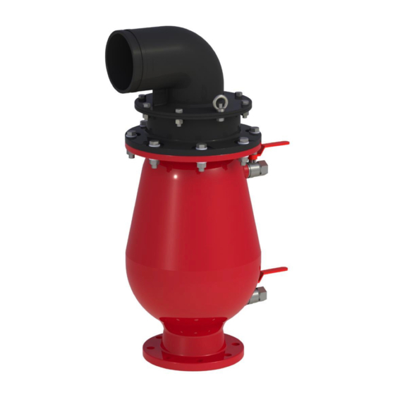
COMBINATION AIR VALVE
MODEL D-26 6" 8"
The following is a step-by-step narrated description of the A.R.I. D-26 combination air valve installation,
operation and maintenance processes.
The D-26 air valve is designed for systems that operate within the pressure and temperature framework of
the model's specifications table. Please consult A.R.I. for products designed for other hazardous liquids
systems.
Advertisement
Table of Contents

Related Manuals for A.R.I. D-26


Summary of Contents for A.R.I. D-26
- Page 1 The following is a step-by-step narrated description of the A.R.I. D-26 combination air valve installation, operation and maintenance processes. The D-26 air valve is designed for systems that operate within the pressure and temperature framework of the model's specifications table. Please consult A.R.I. for products designed for other hazardous liquids...
-
Page 2: Table Of Contents
TABLE OF CONTENTS 1. SAFETY INSTRUCTIONS ..........................3 Safety Instructions - General ............................3 Safety Instructions - Handling ........................... 3 Safety Instructions - Installation ..........................3 Safety Instructions - Commissioning and Operation ....................4 Safety Instructions - Maintenance ..........................4 Safety Instructions - Before returning to regular operation .................. -
Page 3: Safety Instructions
1. SAFETY INSTRUCTIONS Safety Instructions - General A.R.I. products always operate as components in a larger system. It is essential for the system designers, installers, operators and maintenance personnel to comply with all the relevant safety standards. Installation, operation or maintenance of the product should be done only by qualified workers, technicians and/or contractors using only good engineering practices, complying with and observing all conventional safety instructions in order to minimize risk and/or danger and/or hazard to workers, the public or to property in the vicinity in accordance with all relevant local standards. -
Page 4: Safety Instructions - Commissioning And Operation
Safety Instructions - Commissioning and Operation Read carefully the operation instructions prior to any attempt to operate the product. Observe the safety stickers on the product and never perform any operation contradicting the instructions given. In order to achieve maximum performance and smooth operation of the product, it is crucial to perform the startup and first operation procedures exactly as described in this manual. -
Page 5: Installation
2. INSTALLATION Important: Before performing any work on the air valve make sure that all workers on site are familiar with the safety instructions and the relevant local and general safety instructions and work regulations. 2.1. Installation Recommendations Single Air Valve on an Isolating Valve at 45° to Air Valve outlet Two Air Valves on a shared Isolating Valve. -
Page 6: Conventions And Measurements
2.2. Conventions and Measurements This paragraph presents and explains the terms and measurements used for the Installation process. D = Diameter of pipeline d = diameter of riser Isolation H = Height of riser on the pipeline Valve (Measured from crown of pipeline) •... -
Page 7: Installation Instructions
2.3. Installation Instructions 1. Flush the system before installing the air valve to avoid any debris or sharp objects getting into the air valve. 2. Carefully remove the air valve from the shipping package. Unload all air valves carefully to a sturdy level surface taking care not to drop them. -
Page 8: Operation
3. OPERATION When the system is charged and the pipeline begins to fill, the water flowing in the pipeline enters into the combination air valve, raising the air/vacuum and air release floats to their sealing position. During filling, air is discharged mainly through the air/vacuum orifice as well as small amounts of air released through the air release orifice. -
Page 9: Periodic Maintenance
Open the Lower Ball Valve to drain the air valve Body. Leave it open. • Follow the local guidelines for disposal of this liquid. The maintenance procedure of the D-26 air valve is divided into the following two separate processes: • First Stage Maintenance – Back Flushing •... -
Page 10: First Stage Maintenance - Back Flushing
5.2. First Stage Maintenance – Back Flushing Perform when a small leak is detected from the Cover Discharge Elbow, and clogging or debris in the sealing mechanism is suspected, or for periodic maintenance. 1. Connect a water source to the Upper Ball Valve. 2. -
Page 11: Second Stage Maintenance
5.3. Second Stage Maintenance Perform if the first stage doesn't solve the leak, when one of the seals or inner parts needs replacement, or for periodic maintenance to thoroughly clean the valve. 5.3.1 Disassembly 1. Release the pressure and drain the valve as described above (chapter 5.1 Preparation). 2. - Page 12 3. Remove the Cover & Float Assembly: • Attach the Lifting Apparatus to the inner Bridge of the Cover. • Lift up and remove the Float and Seal Assembly together with the Cover. • Place the Cover & Float Assembly on a clean surface. 4.
- Page 13 • Remove the screws from the housing. • Separate the two sections of the Float & Seal Assembly and clean them.
- Page 14 B. Replacing the Automatic Air Release Rolling Seal: • Using To replace the Air Release Rolling Seal [1], pull the seal out of the slots from both ends and discard [2] [3]. • Dip both ends of the new replacement Rolling Seal in the liquid soap [4].
- Page 15 C. Replacing the Air & Vacuum (Kinetic) Seal: • Using a Phillips head screwdriver, turn the 8 Screws on the Air & Vacuum Seal Cover in a counterclockwise direction until they are free and remove them from the Air & Vacuum Seal Cover [1] [2].
- Page 16 D. Cleaning: • Wash and clean all disassembled parts, including the Float & Seal Assembly and the Body and Cover – inside and out, under clean running water to remove all dirt and grime [1] [2] [3]. • Pay special attention that the Air Release Orifice is clean of debris.
- Page 17 5.3.2 Reassembly 1. Closing the Seal Assembly: • Align the 2 grooves of the Slider [1] opposite the 2 legs of the Air/Vacuum Housing [2] and slide inward into place [3]. • Align the 2 holes of the Disc opposite the 2 holes in the legs of the Seal Assembly Housing, insert the 2 screws and screw them tightly into place [3] [4].
-
Page 18: Assembly Bom Table And Drawing
6. ASSEMBLY BOM TABLE and DRAWING Part Discharge Assembly Flange seal (Optional) Grooved flange (optional) Horizontal discharge / Vertical discharge Non-slam Disc - Optional Cover Assembly O-Ring Cover Orifice Seat Seal Assembly Guide Rod Assembly Air & Vacuum Disc Air & Vacuum Seal Air Release Seal &... -
Page 19: Limited Warranty
7. A.R.I. LIMITED WARRANTY A.R.I. Standard International Warranty A.R.I. manufactured products are guaranteed to be free from defect in material and/or workmanship and to perform as advertised when properly installed, used and maintained in accordance with current instructions, written or verbal. Should any item prove defective within the time period set forth for that item(s), but in any case, not later than within 12 (Twelve) months of that product having left A.R.I.’s premises, and subject to receipt by A.R.I.
Need help?
Do you have a question about the D-26 and is the answer not in the manual?
Questions and answers