Table of Contents
Advertisement
Quick Links
®
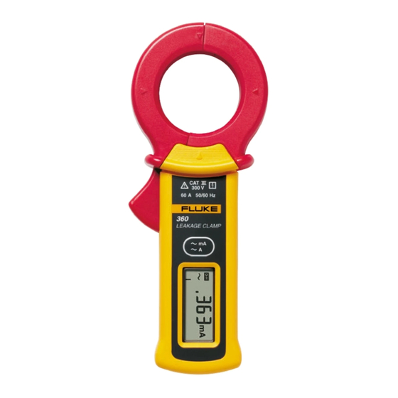
360
AC Leakage Current Clamp Meter
Calibration Information
Introduction
This document provides the following information for the 360 AC Leakage Current Clamp Meter
(hereafter referred to as the Meter or UUT):
• Safety information
• Symbols
• Specifications
• Maintenance
• Performance Tests
• Replacement Parts List
• Product Warranty Statement
For complete operating instructions, refer to the 360 Instruction Sheet.
Contacting Fluke
To order parts, or for warranty service, contact Fluke as follows:
USA: 1-888-99-FLUKE (1-888-993-5853)
Canada: 1-800-36-FLUKE (1-800-363-5853)
Europe: +31 402-675-200
Japan: +81-3-3434-0181
Singapore: +65-738-5655
Anywhere in the world: +1-425-446-5500
Or, visit Fluke's Web site at www.fluke.com.
To register your product, go to register.fluke.com.
October 2007
© 2007 Fluke Corporation. All rights reserved. Specifications are subject to change without notification.
All product names are trademarks of their respective companies.
1
Advertisement
Table of Contents

Related Manuals for Fluke 360


Summary of Contents for Fluke 360
- Page 1 ® AC Leakage Current Clamp Meter Calibration Information Introduction This document provides the following information for the 360 AC Leakage Current Clamp Meter (hereafter referred to as the Meter or UUT): • Safety information • Symbols • Specifications • Maintenance •...
-
Page 2: Safety Information
AC Leakage Current Clamp Meter Safety Information XW Safety Information To avoid electric shock or personal injury, and ensure safe operation and service of the Meter, follow these instructions: • Read the operating instructions before use and follow all safety instructions. -
Page 3: Specifications
DC (Direct Current) Earth ground Application to or removal from hazardous, live conductors is permitted Do not dispose of this product as unsorted municipal waste. Go to Fluke’s Web site for recycling information. Conforms to requirements of European Union Battery... -
Page 4: Maintenance
AC Leakage Current Clamp Meter Dimensions (W x H x D)........70 mm x 176 mm x 25 mm (2.8 in x 6.9 in x 1.0 in) Weight (including battery)........Approximately 200 g (0.44 lb) Safety Specifications Category rating............CAT III 300 V per IEC/EN61010-1, and 61010-2-032 Pollution Degree 2, indoor use EMC ................ -
Page 5: Performance Tests
12 months. In the performance tests, the Meter is referred to as the unit under test (UUT). Before you perform any of the following tests, check the battery and replace if necessary. For more information, see Battery Replacement. If the UUT fails any performance test, contact Fluke Service for repair. See Contacting Fluke. - Page 6 AC Leakage Current Clamp Meter Testing the LCD Use the following procedure to test the LCD: 1. Press the power button and observe the LCD during the selftest startup mode. 2. Compare the LCD with the example in Figure 2. 3.
-
Page 7: Calibration Adjustment
3. Clamp the UUT around the wire coils. 4. Perform the adjustment for each step listed in Table 4 to obtain display reading within the adjustment limits shown. If the UUT fails to meet any expected results, contact Fluke Service for repair. See Contacting Fluke. - Page 8 AC Leakage Current Clamp Meter Table 4. Calibration Adjustment Steps Step Selected Range Wire Coils Calibrator Output Adjustment Adjustment Limits 30 A 13.5, 60 Hz 26.97 to 27.03 3 mA, 60 Hz 2.998 to 3.002 20 mA, 50 Hz Adjust VR5 for same 20 mA, 60 Hz reading at 50 and 60 Hz None...
-
Page 9: Replacement Parts List
Replacement Parts List Replacement Parts List Table 5 lists the replacement parts that are available for the Meter. Figure 4 shows the location of each part. To order replacement parts, see Contacting Fluke. Table 5. Replacement Parts List Reference Description... -
Page 10: Limited Warranty And Limitation Of Liability
Limited Warranty and Limitation of Liability Each Fluke product is warranted to be free from defects in material and workmanship under normal use and service. The warranty period is one year and begins on the date of shipment. Parts, product repairs, and services are warranted for 90 days.
Need help?
Do you have a question about the 360 and is the answer not in the manual?
Questions and answers