Table of Contents
Advertisement
Quick Links
S9361A207x
Integrated Boiler Controllers
APPLICATION
These integrated boiler control modules provide
ignition sequence, flame monitoring and safety
shutoff for intermittent pilot spark ignition heating
systems. This control also provides limit-rated boiler
temperature control with a single limit-rated sensor
and "on-board" display interface capability.
• S9361A20XX - Atmospheric draft appliances.
• S9361A20XX - Induced draft appliances.
• Spark ignition, Intermittent Pilot, Single rod.
• "On board" Display.
• System Circulator and Domestic Hot Water
Circulator output.
• Enabled with EnviraCOM™ communication
capability to support remote monitoring and
diagnostics.
• Limit-rated Temperature Sensing Probe.
• One Sensor Model
INSTALLATION INSTRUCTIONS
SPECIFICATIONS
IMPORTANT:
The specifications given in this publication do
not include normal manufacturing
tolerances. Therefore, an individual unit may
not match the listed specifications exactly.
Also, this product is tested and calibrated
under closely controlled conditions, and some
minor differences in performance can be
expected if those conditions are changed.
Model Numbers
S—Switching Control
9 3—Integrated Hydronic Control Platform
6—Spark Ignition
1—Integrated On-Board Display
A—Boiler Control
2—On/Off Circulator
S 9 3 6 1 A 2
000
69-2751-05
Advertisement
Table of Contents

Related Manuals for Honeywell S9361A207 Series


Summary of Contents for Honeywell S9361A207 Series
- Page 1 S9361A207x Integrated Boiler Controllers INSTALLATION INSTRUCTIONS SPECIFICATIONS IMPORTANT: The specifications given in this publication do not include normal manufacturing tolerances. Therefore, an individual unit may not match the listed specifications exactly. Also, this product is tested and calibrated under closely controlled conditions, and some minor differences in performance can be expected if those conditions are changed.
- Page 2 S9361A207X INTEGRATED BOILER CONTROLLERS Dimensions: See Fig. 1. 1-3/8 (35) (16) M24217 Fig. 1. S936X Integrated Boiler Controller, dimensions in in. (mm). Electrical Ratings: Operating Ambient Temperature: -4°F to +150°F. Line Voltage: 120 Vac, 60 Hz (220 Vac, 50 Hz on spe- Shipping Ambient Temperature: -40°F to +175°F.
-
Page 3: Installation
In these situations, special steps may be required to when the appliance is installed. prevent nuisance shutdowns and premature control failures. These applications require Honeywell Engineering review; contact your Honeywell Sales Representative for assistance. 69-2751—05... -
Page 4: Installation And Checkout
S9361A207X INTEGRATED BOILER CONTROLLERS INSTALLATION AND 1. In such applications, particularly commercial, the equipment can operate 100,000 to 200,000 CHECKOUT cycles per year. Such heavy cycling can wear out the gas control in one to two years. A normal boiler application, for which the controls were When Installing This Product…... - Page 5 S9361A207X INTEGRATED BOILER CONTROLLERS 99.5 M24198 Fig. 2. Recommended slot/hole pattern in appliance (in mm). WATER HEATER CONTROL M24229 Fig. 3. Align module with slots in manufacturer’s control box. 69-2751—05...
- Page 6 105°C Connect Ignition Cable (S936XAXXXX) (221°F) for the ground wire; asbestos insulation is not Use Honeywell ignition cable or construct an ignition acceptable. If necessary, use a shield to protect the cable that conforms to suitable national standards, wire from radiant heat generated by the burner.
-
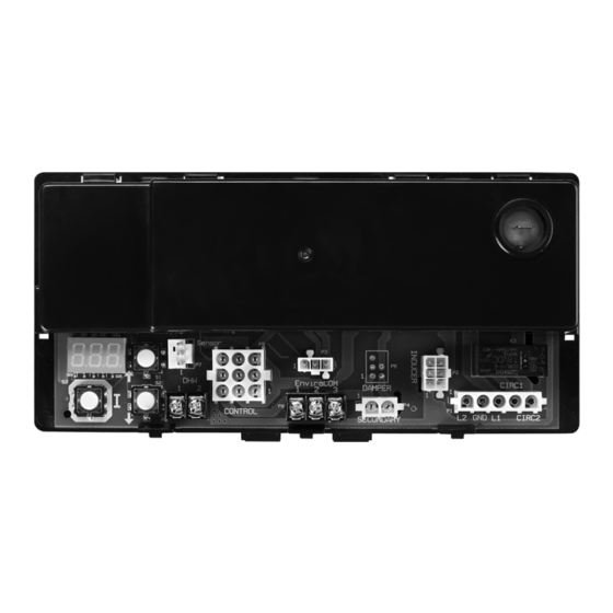
Page 7: Wiring Detail
S9361A207X INTEGRATED BOILER CONTROLLERS Wiring Detail SPARK IGNITER/FLAME SENSE CIRCULATOR SYSTEM CIRCULATOR INDUCER DAMPER (OPTIONAL) (OPTIONAL) 24VAC TRANSFORMER ENVIRACOM PRESSURE SWITCH LIMIT SWITCH T-STAT CONTROL SENSOR M533506 Fig. 4. Spark-to-Pilot Ignition Wiring (S936X). 69-2751—05... - Page 8 S9361A207X INTEGRATED BOILER CONTROLLERS State Code Definitions For induced draft - state codes from 1–17; For atmospheric - state codes from 1–21 Table 5. State Code Definitions. State General State code Specific Description Description Idle The boiler is in standby-no call for heat Standby Run circulator Heat request present but boiler temp sufficiently high to run...
-
Page 9: Temperature Control
S9361A207X INTEGRATED BOILER CONTROLLERS Table 5. State Code Definitions. (Continued) State General State code Specific Description Description Wait for vent Damper actuator is energized and the system waits for damper to close damper to open Wait for vent Damper actuator is de-energize and the system waits for damper to open damper to close Wait for vent Damper actuator is energized, system waits for damper to open, but the damper is... - Page 10 S9361A207X INTEGRATED BOILER CONTROLLERS Table 6. 7-Segment LED Display - Installer Mode Options. (Continued) 3-Digit 7-Segment Display Screen 2nd Screen Screen Default Range Description <Value of Test Parameter 0 to 20 minutes The lower range of the parameter 1> Pump Pre-Purge Time (see above). The parameter might be optionally adjustable (e.g.
-
Page 11: Location And Mounting
Fig. 5. Typical location of limit function sensor and best temperature response. Use heat-conductive control module. compound (Honeywell part no. 107408) to fill the space between the bulb and the well to improve heat transfer characteristics (optional). Make sure the sensor is held firmly in the well. -
Page 12: Operation And Checkout
S9361A207X INTEGRATED BOILER CONTROLLERS Mounting Sensor and to idle and waits for the temperature to drop again. The circulator is turned on throughout the “Call for Thermowell Heat.” The remote upper temperature sensor is installed in See Fig. 7 for a graphical representation of a simple an immersion well (Fig. - Page 13 S9361A207X INTEGRATED BOILER CONTROLLERS IGNITION CIRCULATOR SEQUENCE CONTROL IDLE IDLE ALL OUTPUTS OFF ALL OUTPUTS OFF WATER TEMPERATURE LOW AND THERMOSTAT ACTIVE THERMOSTAT CALL FOR HEAT ACTIVE CHECK LEAKAGE/ WATER TEMP. CIRCULATOR ON SET FLAME BIAS HIGH OR CALL FOR HEAT LOST THERMOSTAT CALL FOR HEAT LOST BIAS DONE TIME OUT OR...
-
Page 14: Ignition System Checks
S9361A207X INTEGRATED BOILER CONTROLLERS TROUBLESHOOTING • Disconnect the ignition cable at the SPARK terminal on the module. IMPORTANT 1. The following service procedures are provided WARNING as a general guide. Follow appliance manufac- The ignition circuit generates over 10,000 turer’s service instructions if available. volts and electrical shock can result. - Page 15 S9361A207X INTEGRATED BOILER CONTROLLERS Table 9. Error Codes. Segment Display Definition Err 2 Pressure Switch failed to open (contacts stuck closed). Err 4 Low flame current Err 6 Flame sensed out of normal sequence (before opening gas valve or after closing gas valve). Err18 Gas valve relays welded 5 consecutive soft lockouts.
-
Page 16: Security Notice
Home and Building Technologies In the U.S.: Honeywell 715 Peachtree Street NE ® U.S. Registered Trademark Atlanta, GA 30308 © 2017 Honeywell International Inc. 69-2751—05 M.S. Rev. 12-17 customer.honeywell.com Printed in United States...
Need help?
Do you have a question about the S9361A207 Series and is the answer not in the manual?
Questions and answers