Table of Contents
Advertisement
Quick Links
Advertisement
Table of Contents

Related Manuals for Honeywell Slate


Summary of Contents for Honeywell Slate
- Page 1 SLATE ™ Limit Control Module R8001L8001 INSTALLATION INSTRUCTIONS...
- Page 2 Scan for more information...
-
Page 3: Specifications
The R8001L8001 SLATE Limit Control Module is part of the SLATE Combustions System. The SLATE Limit Control Module provides the ability to bring in any type of analog signal and create limits on either pressure or temperature without needing a UDC Controller. - Page 4 Federal Communications Commission: Part 15, Class A Must be mounted inside a grounded metal enclosure. Mounting DIN Rail (See Fig. 2) Required Components R8001A1001 SLATE Base Controller R8001S9001 SLATE Sub-Base Module R8001B2001 SLATE Burner Control Module 7-3/32 (181) 2-11/16 (68) 4-19/32 (117) M35382 Fig. 1.
-
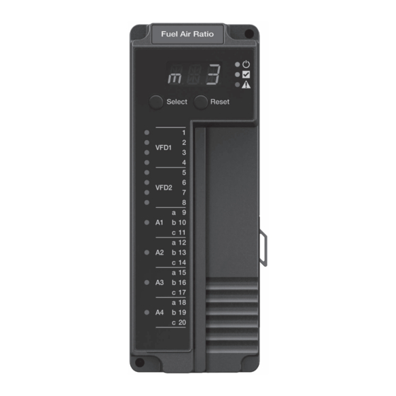
Page 5: Led Array
Table 1. LED Descriptions. LED Display The SLATE system modules have a seven-segment, three- position LED display used for indicating the module number of the SLATE system. The LED colors indicate the terminal state as shown in Table 2. Color Description... -
Page 6: Installation
Select and Reset Buttons The SLATE system modules have a Select and Reset buttons located on the front of the module and beneath the segment display. The Reset button is used to clear a lockout and reset the module. The Select button is used to scroll through the segment display information. -
Page 7: Electrical Shock Hazard
M35383 Fig. 2. Installing the Limit Control Module on the Sub-Base Module. 2. Wiring must comply with all applicable codes, ordinances and regulations. 3. Wiring must comply with NEC Class 1 (Line Voltage) wiring. SLATE LIMIT CONTROL MODULE ™ R8001L8001... - Page 8 IMPORTANT 1. This equipment generates, uses and can radiate radio frequency energy and, if not installed and used in accordance with these instructions, may cause interference for radio communications. It has been tested and found to comply with the limits of a Class A computing device of part 15 of FCC rules, which are designed to provide reasonable protection against such interference when operated in a commercial environment.
- Page 9 CELL SAFETY RELAY UNIVERSAL LOW VOLTAGE CELL UNIVERSAL LOW VOLTAGE CELL UNIVERSAL LOW VOLTAGE CELL SAFETY FROM RELAY POWER LOAD LOADS RELAY VREF+ BIAS VREF– M35285 Fig. 3. Wiring diagram for Limit Control Module. SLATE LIMIT CONTROL MODULE ™ R8001L8001...
- Page 10 Terminal Description Rating Cell A (T1) See Table 4–7 for configuration options Cell A (T2) See Table 4–7 for configuration options Cell A (T3) See Table 4–7 for configuration options Cell A (T4) See Table 4–7 for configuration options Cell B (T5) See Table 4–7 for configuration options Cell B (T6) See Table 4–7 for configuration options...
- Page 11 Accuracy specification given is for 100 Ω load. Resolution specification can be converted to mA by dividing out load. Table 4. Specifications for Basic Cell Functions. Specifications based on worst case over ambient temperatures. SLATE LIMIT CONTROL MODULE ™ R8001L8001...
- Page 12 Complex Functions Typical Max Units Thermocouple T2 & Type J Range -200.0 1025.0 °C Resolution °C Accuracy -5.0 °C Type K Range -150.0 - 1000.0 °C Resolution °C Accuracy -5.0 °C T3 & Range -135.0 - 250.0 °C 3 wire, 100 Ω Type PT100 Resolution °C...
- Page 13 Min. “off” pulse width usec 10V amplitude (high %DC) Duty 125 – 500 90.0 10V amplitude Cycle Resolution Accuracy 125 Hz -1.5 10V amplitude 500 Hz -7.5 10V amplitude Table 6. Specifications for Cell Frequency Functions. SLATE LIMIT CONTROL MODULE ™ R8001L8001...
- Page 14 Configuration Optimum Range for Performance Max Thermocouple J -50°C 1025°C ± 4 °C K -50°C 1000°C ± 4 °C -135°C 250°C ± 2 °C 25°C 125°C ± 1°C Current Out 4 mA 20 mA ± .05 mA Voltage: In / Out 10 V 0.3 %, typical...
-
Page 15: Signal Ground
Be sure loads do not exceed the terminal ratings. Refer to the labels or terminal ratings in Table 2. The SLATE system must be mounted in an electrical enclosure. When mounting in an electrical enclosure, provide adequate clearance for servicing, installation and removal of SLATE modules. - Page 16 32-00007-03 For more information and detailed instructions on the R8001L8001 and the entire SLATE system please refer to the SLATE User Guide located on our website at http://combustion.honeywell.com/SLATE Automation and Control Solutions Honeywell International Inc. ® U.S. Registered Trademark. 1985 Douglas Drive North ©...
Need help?
Do you have a question about the Slate and is the answer not in the manual?
Questions and answers