
Related Manuals for Makita GSL03


Summary of Contents for Makita GSL03
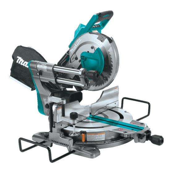
- Page 1 INSTRUCTION MANUAL MANUAL DE INSTRUCCIONES Cordless Slide Compound Miter Saw Sierra de Inglete Inalámbrica GSL03 IMPORTANT: Read Before Using. IMPORTANTE: Lea antes de usar.
-
Page 2: Specifications
ENGLISH (Original instructions) SPECIFICATIONS Model: GSL03 Blade diameter 255 mm (10″) Hole diameter 15.88 mm (5/8″) Max. kerf thickness of the saw blade 3.2 mm (1/8″) Max. miter angle Right 60°, Left 60° Max. bevel angle Right 48°, Left 48°... -
Page 3: General Power Tool Safety Warnings
Personal Safety SAFETY WARNINGS Stay alert, watch what you are doing and use common sense when operating a power tool. For your own safety, read Do not use a power tool while you are tired or under the influence of drugs, alcohol or med- instruction manual before oper- ication. -
Page 4: Safety Instructions For Mitre Saws
Maintain power tools and accessories. Check Never service damaged battery packs. Service for misalignment or binding of moving parts, of battery packs should only be performed by the breakage of parts and any other condition that manufacturer or authorized service providers. may affect the power tool’s operation. - Page 5 Do not reach behind the fence with either hand 17. If the workpiece or blade becomes jammed, closer than 100 mm from either side of the saw turn the mitre saw off. Wait for all moving blade, to remove wood scraps, or for any other parts to stop and disconnect the plug from reason while the blade is spinning.
- Page 6 10. Check the blade carefully for cracks or dam- Symbols age before operation. Replace cracked or dam- aged blade immediately. Gum and wood pitch The followings show the symbols used for tool. hardened on blades slows saw and increases potential for kickback. Keep blade clean by volts first removing it from tool, then cleaning it with gum and pitch remover, hot water or kerosene.
- Page 7 17. Do not remove the wireless unit from the slot causing fires, personal injury and damage. It will while the power is being supplied to the tool. also void the Makita warranty for the Makita tool and Doing so may cause a malfunction of the wireless charger.
-
Page 8: Parts Description
25. When storing the wireless unit, keep it in the supplied case or a static-free container. 26. Do not insert any devices other than Makita wireless unit into the slot on the tool. 27. Do not use the tool with the lid of the slot dam- aged. -
Page 9: Installation
Handle Battery cartridge Dust bag (when replaced Hose (for dust with dust extraction extraction) hose) 0° adjusting bolt (for Bevel angle scale Pointer (for bevel angle) 45° adjusting bolt (for bevel angle) bevel angle) Latch lever (for bevel Releasing lever (for 48° Guide fence (upper Guide fence (lower angle) -
Page 10: Bench Mounting
To remove the sleeve of the hose from the port, pull the Installing and removing dust sleeve while pressing the stopper buttons on both sides extraction hose of the port. Attach the hose elbow to the upper port with the lock button facing upwards. -
Page 11: Functional Description
This tool should be bolted with four bolts to a level and stable surface using the bolt holes provided in the tool's base. This will help prevent tipping and possible injury. ► 1. Red indicator 2. Button 3. Battery cartridge To remove the battery cartridge, slide it from the tool while sliding the button on the front of the cartridge. -
Page 12: Handle Lock
Indicating the remaining battery Handle lock capacity CAUTION: Always hold the handle when Press the check button on the battery cartridge to indi- releasing the stopper pin. Otherwise the handle cate the remaining battery capacity. The indicator lamps springs up and it may result in personal injury. light up for a few seconds. -
Page 13: Blade Guard
WARNING: Do not remove spring holding blade guard. If guard becomes damaged in course of time or UV light exposure, contact a Makita ser- ► 1. Blade guard vice center for replacement. DO NOT DEFEAT OR REMOVE GUARD. Cleaning... - Page 14 NOTE: The rear screws can easily be loosened and NOTICE: When changing bevel angles, be sure tightened by turning the turn base at an angle. Make to reposition the kerf boards appropriately. sure to raise the handle fully when turning the turn NOTICE: Always remove the upper guide fences base.
- Page 15 Push the carriage toward the guide fences fully Rotate the blade by hand while holding the handle and lower the handle completely. all the way down to be sure that the circular saw blade does not contact any part of the lower base. Re-adjust slightly, if necessary.
-
Page 16: Adjusting The Miter Angle
Positive stop function CAUTION: Always hold the handle firmly when adjusting. Failure to do so may cause the This miter saw employs positive stop function. You can carriage to jump up and result in injury. set 0°, 15°, 22.5°, 31.6°, 45°, and 60° right/left miter angle quickly. -
Page 17: Adjusting The Bevel Angle
Align the pointer with your desired angle on the Adjusting the bevel angle bevel angle scale. Tighten the knob clockwise to secure the carriage CAUTION: After changing the bevel angle, arm. always secure the arm by tightening the knob on the slide pole clockwise. - Page 18 Tilting the circular saw blade to the Tilting the circular saw blade using right positive stop function Rotate the knob on the slide pole This miter saw employs positive stop function. You can counterclockwise. set 22.5° and 33.9° angle to both right and left quickly. Hold the handle and tilt the carriage to the left Rotate the knob on the slide pole slightly.
-
Page 19: Switch Action
A switch in need of repair may result in unintentional operation and serious personal injury. Return tool to a Makita service center for proper repairs BEFORE further usage. ► 1. Switch trigger 2. Lock-off button 3. Hole for ►... -
Page 20: Electronic Function
CAUTION: Do not touch the lens of the lamp a Makita service center. as it is very hot while it is lighted or shortly after it is turned off. This may cause burns. -
Page 21: Removing And Installing Saw Blade
Accidental start up of the tool may result in serious personal injury. WARNING: Use only the Makita wrench pro- vided to remove and install the circular saw blade. Failure to use the wrench may result in overtightening or insufficient tightening of the hex socket bolt and serious personal injury. -
Page 22: Installing The Blade
When you wish to perform clean cutting operation, con- on the circular saw blade matches the direction of the nect a Makita vacuum cleaner to the dust nozzle (upper arrow on the blade case. dust port) using a front cuff 24 (optional accessory). -
Page 23: Securing Workpiece
Dust bag Securing workpiece CAUTION: WARNING: When performing a cutting, always It is extremely important to always attach the dust bag or connect a vacuum cleaner secure the workpiece correctly with the proper to prevent dust-related hazards. type of vise or crown molding stoppers. Failure to do so may result in serious personal injury and cause The use of the dust bag makes cutting operations clean damage to the tool and/or the workpiece. - Page 24 Use upper fences to support the material higher than Vertical vise the lower fences. Insert the upper fence into the hole on the lower fence and tighten the clamping screw. WARNING: The workpiece must be secured firmly against the turn base and guide fences with the vise during all operations.
- Page 25 Holders NOTE: For a quick setting of workpiece, turning the vise knob to 90° counterclockwise allows the vise knob to be moved up and down. To secure the work- WARNING: Always support a long workpiece piece after setting, turn the vise knob clockwise. so it is level with the top surface of the turn base for an accurate cut and to prevent dangerous loss Horizontal vise...
-
Page 26: Operation
Aluminum products When cutting, place the workpiece flat against the guide Refer to our website or contact your local Makita dealer fence and the sub fence on the sub base. for the correct circular saw blades to be used for the material to be cut. - Page 27 Slide (push) cutting (cutting wide NOTICE: Before use, be sure to unlock the stopper pin and release the handle from the lowered position. workpieces) NOTICE: Do not apply excessive pressure on the han- dle when cutting. Too much force may result in overload of WARNING: Whenever performing a slide cut, the motor and/or decreased cutting efficiency.
-
Page 28: Miter Cutting
Miter cutting Compound cutting Refer to the section for adjusting the miter angle. Compound cutting is the process in which a bevel angle is made at the same time in which a miter angle Bevel cutting is being cut on a workpiece. Compound cutting can be performed at the angle shown in the table. - Page 29 In the case of left bevel cut (a) (b) (c) (d) 1. Inside corner 2. Outside corner 1. Inside corner 2. Outside corner Measuring Table (A) Measure the wall width, and adjust the width of the workpiece according to it. Always make sure that width –...
- Page 30 In the case of right bevel cut (a) (b) (c) (d) 1. Inside corner 2. Outside corner Table (A) – Molding Bevel angle Miter angle position 52/38° 45° type 52/38° 45° type in the type type figure Right Right Right Right inside 33.9°...
- Page 31 Miter and Bevel Angle Settings Wall to Crown Molding Angle: 52°/38° 43.0 46.8 30.1 26.9 15.3 12.3 42.8 46.3 29.7 26.5 14.9 12.0 42.5 45.7 29.4 26.1 14.5 11.6 42.2 45.1 29.0 25.7 14.1 11.3 41.9 44.6 28.7 25.3 13.7 11.0 41.7 44.0...
- Page 32 Wall to Crown Molding Angle: 45° 37.8 50.8 26.7 30.2 13.7 14.1 37.5 50.2 26.4 29.8 13.3 13.7 37.3 49.6 26.1 29.4 13.0 13.3 37.1 49.1 25.8 28.9 12.6 12.9 36.8 48.5 25.5 28.5 12.3 12.6 36.6 48.0 25.2 28.1 11.9 12.2 36.4...
- Page 33 Crown molding stopper Position crown molding with its WALL CONTACT EDGE against the guide fence and its CEILING CONTACT Optional accessory EDGE against the crown molding stoppers as shown in the figure. Adjust the crown molding stoppers according Crown molding stoppers allow easier cuts of crown to the size of the crown molding.
-
Page 34: Groove Cutting
After adjusting the lower limit position of the circu- Cutting aluminum extrusion lar saw blade, cut parallel grooves across the width of the workpiece using a slide (push) cut. ► 1. Cut grooves with blade Remove the workpiece material between the grooves with a chisel. - Page 35 Installing the wireless unit CAUTION: Always secure all moving portions before carrying the tool. If portions of the tool move Optional accessory or slide while being carried, loss of control or balance may occur and result in personal injury. CAUTION: Place the tool on a flat and stable CAUTION: Be sure that the carriage elevation...
- Page 36 Tool registration for the vacuum cleaner NOTE: A Makita vacuum cleaner supporting the wireless activation function is required for the tool registration. NOTE: Finish installing the wireless unit to the tool before starting the tool registration.
- Page 37 Set the stand-by switch on the vacuum cleaner to NOTE: The wireless activation lamps finish blinking "AUTO". in green after 20 seconds elapsed. Press the wireless activation button on the tool while the wireless acti- vation lamp on the cleaner is blinking. If the wireless activation lamp does not blink in green, push the wire- less activation button briefly and hold it down again.
- Page 38 NOTE: The wireless activation lamp on the tool will stop blinking in blue when there is no operation for 2 hours. In this case, set the stand-by switch on the vacuum cleaner to "AUTO" and push the wireless activation button on the tool again. NOTE: The vacuum cleaner starts/stops with a delay.
- Page 39 If the cancellation is performed successfully, the wire- Cancelling tool registration for the less activation lamps will light up in red for 2 seconds vacuum cleaner and start blinking in blue. NOTE: The wireless activation lamps finish blinking in Perform the following procedure when cancelling the red after 20 seconds elapsed.
- Page 40 Before asking for repairs, conduct your own inspection first. If you find a problem that is not explained in the manual, do not attempt to dismantle the tool. Instead, ask Makita Authorized Service Centers, always using Makita replace- ment parts for repairs.
-
Page 41: Maintenance
Lower the be performed by Makita Authorized or Factory Service carriage fully and lock it in the lowered position with Centers, always using Makita replacement parts. - Page 42 Carefully square the side of the circular saw blade with If the pointer does not indicate the 45° position, align it the top surface of the turn base using the triangular with the 45° position by turning the adjusting bolt in the rule, try-square, etc.
-
Page 43: After Use
OPTIONAL ACCESSORIES WARNING: These Makita accessories or attachments are recommended for use with your Makita tool specified in this manual. The use of any other accessories or attachments may result in serious personal injury. WARNING: Only use the Makita accessory or attachment for its stated purpose. -
Page 44: Especificaciones
ESPAÑOL (Instrucciones originales) ESPECIFICACIONES Modelo: GSL03 Diámetro del disco 255 mm (10″) Diámetro del orificio 15,88 mm (5/8″) Ancho de corte máx. del disco de la sierra 3,2 mm (1/8″) Ángulo de inglete máximo Derecho 60°, izquierdo 60° Ángulo de bisel máximo Derecho 48°, izquierdo 48°... -
Page 45: Advertencias De Seguridad
No maltrate el cable. Nunca utilice el cable ADVERTENCIAS DE para transportar, jalar o desconectar la herra- mienta eléctrica. Mantenga el cable alejado del SEGURIDAD calor, aceite, objetos cortantes o piezas móvi- les. Los cables dañados o enredados aumentan el riesgo de sufrir una descarga eléctrica. Por su propia seguridad lea el Cuando utilice una herramienta eléctrica en manual de instrucciones Antes... - Page 46 Si dispone de dispositivos para la conexión de Mantenga los mangos y superficies de asi- equipos de extracción y recolección de polvo, miento secos, limpios y libres de aceite o asegúrese de conectarlos y utilizarlos debida- grasa. Los mangos y superficies de asimiento mente.
- Page 47 No acerque las manos por detrás de la guía a Instrucciones de seguridad para más de 100 mm de distancia de ambos lados sierras de inglete del disco de la sierra para extraer restos de madera ni por ninguna otra razón mientras el Las sierras de inglete están diseñadas para disco esté...
- Page 48 15. Utilice siempre una abrazadera o algún acce- No utilice la sierra sin los protectores pues- sorio diseñado para apoyar adecuadamente tos. Verifique que el protector del disco cierre materiales redondos tales como varillas o debidamente antes de cada uso. No utilice la tubos.
- Page 49 18. Asegúrese de que el disco no esté haciendo Instrucciones importantes de contacto con la pieza de trabajo antes de acti- seguridad para el cartucho de var el interruptor. batería 19. Antes de utilizar la herramienta en una pieza de trabajo definitiva, déjela funcionar durante un rato.
- Page 50 Asimismo, esto inva- 12. Retire siempre la batería del producto al insta- lidará la garantía de Makita para la herramienta y el lar en él la unidad inalámbrica. cargador Makita.
-
Page 51: Descripción De Las Piezas
22. No deje la unidad inalámbrica en un lugar 26. No inserte ningún otro dispositivo que no sea donde haya polvo o suciedad ni en un lugar la unidad inalámbrica de Makita en la ranura de donde pueda generarse gas corrosivo. la herramienta. -
Page 52: Instalación
Empuñadura Cartucho de batería Bolsa recolectora de Manguera (para la polvo (cuando se reem- extracción de polvo) plaza con la manguera de extracción de polvo) Perno de ajuste de 0° Escala del ángulo de Marcador (para el Perno de ajuste de 45° (para el ángulo de bisel) bisel ángulo de bisel) - Page 53 Para quitar el manguito de la manguera del puerto, tire Instalación y remoción de la del manguito mientras presiona los botones de tope de manguera de extracción de polvo ambos lados del puerto. Conecte el codo de la manguera al puerto superior con el botón de bloqueo hacia arriba.
-
Page 54: Descripción Del Funcionamiento
Esta herramienta debe fijarse con cuatro pernos a una superficie nivelada y estable usando los orificios para pernos provistos en la base de la herramienta. Esto ayudará a evitar que la herramienta se vuelque y provo- que lesiones. ► 1. Indicador rojo 2. Botón 3. Cartucho de batería Para quitar el cartucho de batería, deslícelo de la herra- mienta mientras desliza el botón sobre la parte delan- tera del cartucho. - Page 55 Protección contra sobredescarga La empuñadura se puede bloquear en la posición descendida o en la posición elevada con la clavija de Cuando la capacidad de la batería se reduce, la herra- retención. Baje o suba la empuñadura completamente, mienta se detiene automáticamente. Si la herramienta y luego tire y gire la clavija de retención en una posición no funciona con la operación del interruptor, extraiga la bloqueada.
- Page 56 Si el protector se daña con el trans- curso del tiempo o por exposición a luz ultravioleta, póngase en contacto con un centro de servicio Makita para solicitar un repuesto. NO INHABILITE NI RETIRE EL PROTECTOR.
- Page 57 NOTA: Los tornillos de la parte posterior se pueden aflojar y apre- AVISO: Cuando cambie los ángulos de bisel, tar fácilmente girando la base giratoria en ángulo. Asegúrese de asegúrese de reposicionar adecuadamente los subir completamente la empuñadura cuando gire la base giratoria. paneles de corte.
- Page 58 Empuje el carro hacia las guías laterales por Gire el disco manualmente mientras sostiene la completo y baje la empuñadura totalmente. empuñadura completamente hacia abajo para asegurar que el disco de la sierra circular no haga contacto con ninguna pieza de la base inferior. Reajuste ligeramente, en caso necesario.
-
Page 59: Brazo De Retención
Libere la palanca de bloqueo y apriete la perilla. Brazo de retención La posición del límite inferior del disco de la sierra circular puede ser ajustada fácilmente con el brazo de retención. Para hacerlo, mueva el brazo de retención en dirección de la flecha, tal como se muestra en la figura. -
Page 60: Ajuste Del Ángulo De Bisel
Jale y gire la palanca de la aldabilla a la posición NOTA: Para liberar la base giratoria de la función de que se muestra en la ilustración. tope de seguridad, presione hacia abajo la palanca de liberación. La base giratoria se puede mover libremente sin mantener presionada la palanca de bloqueo. - Page 61 Inclinación del disco de la sierra Inclinación del disco de la sierra circular a la derecha circular con función de tope de seguridad Rote el pomo del soporte de corredera en sentido inverso al de las manecillas del reloj. Esta sierra de inglete emplea la función de tope de Sostenga la empuñadura e incline el carro a la seguridad.
-
Page 62: Accionamiento Del Interruptor
El uso de un interruptor que requiere reparación puede ocasionar una operación accidental y lesiones personales graves. Lleve la herramienta a un centro de servicio Makita para las reparaciones apropiadas ANTES de continuar su uso. ► 1. Pomo 2. Empuñadura 3. Palanca de liberación para el ángulo de bisel de 48°... -
Page 63: Montaje
PRECAUCIÓN: No toque el lente de la lám- servicio Makita para que le den mantenimiento. para ya que éste llega a calentarse mucho cuando está encendida o poco después de haberla apa- PRECAUCIÓN:... -
Page 64: Extracción Del Disco
ADVERTENCIA: Utilice sólo la llave Makita provista para extraer e instalar el disco de la sie- rra circular. El no utilizar la llave podría ocasionar un apriete excesivo o insuficiente del perno de cabeza hexagonal y provocar lesiones personales graves. -
Page 65: Instalación Del Disco
Cuando desee realizar una operación de corte limpia, conecte una aspiradora Makita a la boquilla para polvo (puerto superior para polvo) usando un manguito delan- tero 24 (accesorio opcional). - Page 66 Bolsa recolectora de polvo Aseguramiento de la pieza de trabajo PRECAUCIÓN: Cuando realice un corte, siempre coloque la bolsa recolectora de polvo o ADVERTENCIA: Es sumamente importante conecte una aspiradora para evitar los riesgos asegurar siempre la pieza de trabajo de manera relacionados con el polvo.
-
Page 67: Prensa Vertical
Utilice las guías superiores para apoyar el material más Prensa vertical arriba de las guías inferiores. Inserte la guía superior en el orificio de la guía inferior y apriete el tornillo de ADVERTENCIA: fijación. La pieza de trabajo deberá estar firmemente sujetada contra la base giratoria y la guía lateral con la prensa durante todas las ope- raciones. - Page 68 Soportes NOTA: Para un ajuste rápido de la pieza de trabajo, gire el seguro de la prensa 90° en sentido inverso al de las manecillas del reloj para poder moverlo hacia ADVERTENCIA: Apoye siempre una pieza de arriba y hacia abajo. Una vez ajustada la pieza de trabajo de gran tamaño de tal forma que esté...
-
Page 69: Operación
► 1. Perno 2. Guía auxiliar 3. Guía lateral 4. Barra rígida OPERACIÓN Esta herramienta está diseñada para cortar productos de madera. Con los discos de la sierra apropiados y originales de Makita también se pueden cortar los siguientes materiales: ► 1. Base inferior 2. Tornillo — Productos de aluminio Consulte nuestro sitio web o póngase en contacto con... - Page 70 Luego baje lentamente la empuñadura a la posi- AVISO: Antes de usar la herramienta, asegúrese ción completamente hacia abajo para realizar el corte de desbloquear la clavija de retención y liberar la en la pieza de trabajo. empuñadura de la posición hacia abajo. Una vez finalizado el corte, apague la herramienta y AVISO: No haga excesiva presión sobre la empu-...
-
Page 71: Corte En Bisel
Encienda la herramienta sin que el disco de la Ajuste el ángulo de bisel conforme al procedi- sierra haga contacto alguno y espere hasta que ésta miento explicado en la sección para ajuste del ángulo alcance la velocidad máxima. de bisel. Luego apriete el pomo. Presione hacia abajo la empuñadura y empuje el carro Asegure la pieza de trabajo con una prensa. - Page 72 En caso de corte en bisel izquierdo Existen juntas de molduras corona y molduras cóncavas que se realizan para ser insertadas en rincones “Internos” de 90° ((a) y (b) en la figura) y rincones “Externos” de 90° ((c) y (d) en la figura). (a) (b) (c) (d) (a) (b)
- Page 73 En caso de un corte en bisel derecho (a) (b) (c) (d) 1. Rincón interno 2. Rincón externo Tabla (A) – Posición Ángulo de bisel Ángulo de inglete de la Tipo de Tipo Tipo de Tipo moldura 52/38° de 45° 52/38°...
- Page 74 Ajustes del ángulo de inglete y de bisel De la pared al ángulo de la moldura corona: 52°/38° 43.0 46.8 30.1 26.9 15.3 12.3 42.8 46.3 29.7 26.5 14.9 12.0 42.5 45.7 29.4 26.1 14.5 11.6 42.2 45.1 29.0 25.7 14.1 11.3 41.9...
- Page 75 De la pared al ángulo de la moldura corona: 45° 37.8 50.8 26.7 30.2 13.7 14.1 37.5 50.2 26.4 29.8 13.3 13.7 37.3 49.6 26.1 29.4 13.0 13.3 37.1 49.1 25.8 28.9 12.6 12.9 36.8 48.5 25.5 28.5 12.3 12.6 36.6 48.0 25.2...
- Page 76 Tope para moldura de corona Coloque la moldura de corona con el BORDE DE CONTACTO CON LA PARED apoyado contra la guía Accesorio opcional lateral y el BORDE DE CONTACTO CON EL TECHO apoyado contra los topes para moldura de corona tal Los topes para moldura de corona permiten cortar más como se muestra en la ilustración.
-
Page 77: Corte De Ranuras
Tras ajustar la posición del límite inferior del disco Corte de extrusión de aluminio de la sierra circular, haga dos cortes paralelos a todo lo largo del ancho de la pieza de trabajo usando un corte por deslizamiento (empuje). ► 1. Corte de ranura con disco Retire el material de la pieza de trabajo que haya quedado en las ranuras con un cincel. - Page 78 Instalación de la unidad inalámbrica ADVERTENCIA: La clavija de retención para la elevación del carro debe usarse únicamente Accesorio opcional para fines de transporte y almacenamiento y no para ninguna operación de corte. El uso de la PRECAUCIÓN: Coloque la herramienta sobre clavija de retención para operaciones de corte puede una superficie plana y estable cuando vaya a causar un movimiento inesperado del disco de la...
- Page 79 Registro de la herramienta para la aspiradora NOTA: Para el registro de la herramienta, se requiere una aspiradora Makita compatible con la función de activación inalámbrica. NOTA: Termine de instalar la unidad inalámbrica en la herramienta antes de comenzar con el registro de la herramienta.
- Page 80 Conecte la manguera de la aspiradora a la herramienta. NOTA: Las luces indicadoras de activación inalám- brica terminarán parpadeando en verde después de un lapso de 20 segundos. Oprima el botón de acti- vación inalámbrica en la herramienta mientras la luz indicadora de activación inalámbrica en la aspiradora esté...
- Page 81 Para detener la operación de la aspiradora, suelte NOTA: La luz indicadora de activación inalámbrica en el gatillo interruptor u oprima el botón de aspiradora la herramienta dejará de parpadear en azul cuando nuevamente. La aspiradora deja de funcionar unos no haya operación durante 2 horas.
- Page 82 Si la cancelación se realiza exitosamente, las luces Cancelación del registro de la indicadoras de activación inalámbrica se encenderán herramienta para la aspiradora en rojo durante 2 segundos y comenzarán a parpadear en azul. Realice el siguiente procedimiento para cancelar el NOTA: Las luces indicadoras de activación inalám- registro de la herramienta para la aspiradora.
- Page 83 Antes de solicitar alguna reparación, primero realice una inspección por su cuenta. Si detecta algún problema que no esté explicado en el manual, no intente desensamblar la herramienta. En vez de esto, solicite la reparación a un centro de servicio autorizado de Makita, usando siempre piezas de repuesto Makita. Estado de la anomalía Causa probable (avería)
-
Page 84: Mantenimiento
Para mantener la SEGURIDAD y FIABILIDAD del pro- MANTENIMIENTO ducto, las reparaciones, y cualquier otra tarea de man- tenimiento o ajuste deberán ser realizadas en centros de servicio autorizados o de fábrica Makita, empleando ADVERTENCIA: Asegúrese siempre de que siempre repuestos Makita. -
Page 85: Ajuste Del Ángulo De Corte
Ángulo de bisel Ajuste del ángulo de corte Ángulo de bisel de 0° Esta herramienta ya viene cuidadosamente ajustada y alineada de fábrica, pero una manipulación descuidada Empuje el carro hacia las guías laterales y bloquee el movi- podría afectar la alineación. Si su herramienta no está miento de deslizamiento con la clavija de retención. - Page 86 Ángulo de bisel de 45° Limpieza del lente de la lámpara AVISO: Antes de ajustar el ángulo de bisel de 45°, termine de ajustar el ángulo de bisel de 0°. PRECAUCIÓN: Antes de limpiar el lente de la lámpara, siempre retire el disco de la sierra Afloje el pomo e incline el carro completamente hacia el circular.
-
Page 87: Accesorios Opcionales
ACCESORIOS OPCIONALES ADVERTENCIA: Estos accesorios o adi- tamentos Makita están recomendados para utilizarse con su herramienta Makita que se especifica en este manual. El uso de cualquier otro accesorio o aditamento puede ocasionar lesiones personales graves. ADVERTENCIA: Use los accesorios o adi- tamentos Makita solamente para su propósito... - Page 88 Para reducir la exposición a estos productos químicos: trabaje en un área bien ventilada y póngase el equipo de seguridad indicado, tal como las máscaras contra polvo que están especialmente diseñadas para filtrar partículas microscópicas. Makita Corporation 3-11-8, Sumiyoshi-cho, Anjo, Aichi 446-8502 Japan 885893-941...
Need help?
Do you have a question about the GSL03 and is the answer not in the manual?
Questions and answers