
Related Manuals for Makita GSL02


Summary of Contents for Makita GSL02
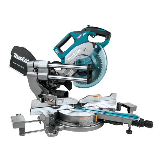
- Page 1 INSTRUCTION MANUAL MANUAL DE INSTRUCCIONES Cordless Slide Compound Miter Saw Sierra de Inglete Inalámbrica GSL02 IMPORTANT: Read Before Using. IMPORTANTE: Lea antes de usar.
-
Page 2: Specifications
ENGLISH (Original instructions) SPECIFICATIONS Model: GSL02 Blade diameter 216 mm (8-1/2″) Hole (arbor) diameter (country specific) 15.88 mm (5/8″) Max. kerf thickness of the saw blade 2.4 mm (3/32″) Max. miter angle Left 60°, Right 60° Max. bevel angle Left 48°, Right 48°... - Page 3 Avoid body contact with earthed or grounded Always wear protective goggles to protect your surfaces, such as pipes, radiators, ranges and eyes from injury when using power tools. The refrigerators. There is an increased risk of elec- goggles must comply with ANSI Z87.1 in the USA. It is an employer's responsibility to enforce the tric shock if your body is earthed or grounded.
-
Page 4: Safety Instructions For Mitre Saws
Under abusive conditions, liquid may be Never cross your hand over the intended line ejected from the battery; avoid contact. If con- of cutting either in front or behind the saw tact accidentally occurs, flush with water. If blade. Supporting the workpiece "cross handed" liquid contacts eyes, additionally seek medical i.e. - Page 5 13. Do not use another person as a substitute for Do not operate saw without guards in place. a table extension or as additional support. Check blade guard for proper closing before each use. Do not operate saw if blade guard Unstable support for the workpiece can cause the does not move freely and close instantly.
- Page 6 Avoid storing battery cartridge in a con- causing fires, personal injury and damage. It will tainer with other metal objects such as also void the Makita warranty for the Makita tool and nails, coins, etc. charger. Do not expose battery cartridge to water or rain.
- Page 7 Do not disassemble or tamper with the wire- supplied case or a static-free container. less unit. 26. Do not insert any devices other than Makita Keep the wireless unit away from young chil- wireless unit into the slot on the tool.
-
Page 8: Parts Description
PARTS DESCRIPTION Hex wrench Adjusting bolt (for maxi- Adjusting screw (for Stopper arm mum cutting capacity) lower limit position) Wireless activation Wireless activation lamp Vacuum button Lamp button button Blade guard Kerf board Grip (for turn base) Grip dial (for bevel angle) Releasing lever (for turn Adjusting bolt (for turn... -
Page 9: Installation
Hole for padlock Switch trigger Lock-off button Carry handle Battery cartridge Dust extraction hose Left bevel angle scale Pointer (for left bevel angle) Releasing lever (for 48° 45° adjusting bolt (for left Shaft lock Dust bag (when replaced bevel angle) bevel angle) with dust extraction hose) -
Page 10: Functional Description
Turn the adjusting bolt clockwise or counterclock- To remove the elbow from the port, pull the elbow while wise so that it comes into a contact with the floor sur- pressing down the lock button. face to keep the tool stable. To remove the sleeve from the port, turn it clockwise and then pull it apart. -
Page 11: Overload Protection
Indicating the remaining battery capacity Press the check button on the battery cartridge to indi- cate the remaining battery capacity. The indicator lamps light up for a few seconds. ► 1. Red indicator 2. Button 3. Battery cartridge To remove the battery cartridge, slide it from the tool while sliding the button on the front of the cartridge. -
Page 12: Handle Lock
Handle lock Blade guard CAUTION: WARNING: Always hold the handle when Never defeat or remove the blade releasing the stopper pin. Otherwise the handle guard or the spring which attaches to the guard. springs up and it may result in personal injury. An exposed blade as a result of defeated guarding may result in serious personal injury during operation. - Page 13 WARNING: Do not remove spring holding blade guard. If guard becomes damaged in course of time or UV light exposure, contact a Makita service center for replacement. DO NOT DEFEAT OR REMOVE GUARD. Positioning kerf board This tool is provided with the kerf boards in the turn base to minimize tearing on the exit side of a cut.
- Page 14 12. After adjusting the kerf boards, release the stop- Rotate the blade by hand while holding the handle per pin for handle lock and raise the handle. Then all the way down to be sure that the circular saw blade tighten all the screws securely.
-
Page 15: Adjusting The Miter Angle
Positive stop function Adjusting the miter angle This miter saw employs positive stop function. You can set 0°, 15°, 22.5°, 31.6°, 45°, and 60° right/left miter CAUTION: After changing the miter angle, angle quickly. always secure the turn base by returning the releasing lever in a locked position and tightening Turn the base close to your desired positive stop the grip firmly. - Page 16 Tilting the circular saw blade to the Tilting the circular saw blade to the left right Rotate the grip dial counterclockwise. Rotate the grip dial counterclockwise. Hold the handle and tilt the carriage to the left. Hold the handle and tilt the carriage to the left slightly.
-
Page 17: Switch Action
A switch in need of repair may result in unintentional operation and serious personal injury. Return tool to a Makita service center for proper repairs BEFORE further usage. ► 1. Grip dial 2. Handle 3. Releasing lever for 48°... -
Page 18: Electronic Function
CAUTION: Do not touch the lens of the lamp a Makita service center. as it is very hot while it is lighted or shortly after it is turned off. This may cause burns. -
Page 19: Removing And Installing Saw Blade
Accidental start up of the tool may result in serious personal injury. WARNING: Use only the Makita wrench pro- vided to remove and install the circular saw blade. Failure to use the wrench may result in overtightening or insufficient tightening of the hex socket bolt and serious personal injury. -
Page 20: Installing The Blade
To install the circular saw blade, perform the following When you wish to perform clean cutting operation, con- steps: nect a Makita vacuum cleaner to the dust nozzle (upper Mount the circular saw blade carefully onto the dust port) using a front cuff 24 (optional accessory). -
Page 21: Securing Workpiece
Dust bag Securing workpiece CAUTION: WARNING: When performing a cutting, always It is extremely important to always attach the dust bag or connect a vacuum cleaner secure the workpiece correctly with the proper to prevent dust-related hazards. type of vise. Failure to do so may result in serious personal injury and cause damage to the tool and/or The use of the dust bag makes cutting operations clean the workpiece. - Page 22 Use upper fences to support the material higher than the lower fences. Loosen the clamping screw so that the upper fences slide in and out over the lower fences. Reposition the fences and then tighten the screw. ► 1. Holes 2. Vise rod 3. Vise arm 4. Clamping screw 5.
-
Page 23: Operation
Aluminum products so it is level with the top surface of the turn base Refer to our website or contact your local Makita dealer for an accurate cut and to prevent dangerous loss for the correct circular saw blades to be used for the of tool control. -
Page 24: Miter Cutting
Gently lower the handle to the fully lowered posi- When the cut is completed, switch off the tool and tion to cut the workpiece. wait until the circular saw blade has come to a com- plete stop before returning the circular saw blade to its When the cut is completed, switch off the tool and fully elevated position. -
Page 25: Compound Cutting
Cutting crown and cove moldings NOTICE: When pressing down the handle, apply pressure in parallel with the circular saw blade. If a force is applied perpendicularly to the turn base or Crown and cove moldings can be cut on a compound if the pressure direction is changed during a cut, the miter saw with the moldings laid flat on the turn base. - Page 26 Measuring Table (B) Measure the wall width, and adjust the width of the – Molding Molding Finished position in edge against piece workpiece according to it. Always make sure that width the figure guide fence of the workpiece's wall contact edge is the same as wall length.
- Page 27 Table (B) – Molding Molding Finished position in edge against piece the figure guide fence For inside Wall contact Finished corner edge should piece will be be against on the Right guide fence. side of blade. Ceiling contact edge For outside Finished should be corner...
- Page 28 Miter and Bevel Angle Settings Wall to Crown Molding Angle: 52°/38° 43.0 46.8 30.1 26.9 15.3 12.3 42.8 46.3 29.7 26.5 14.9 12.0 42.5 45.7 29.4 26.1 14.5 11.6 42.2 45.1 29.0 25.7 14.1 11.3 41.9 44.6 28.7 25.3 13.7 11.0 41.7 44.0...
- Page 29 Wall to Crown Molding Angle: 45° 37.8 50.8 26.7 30.2 13.7 14.1 37.5 50.2 26.4 29.8 13.3 13.7 37.3 49.6 26.1 29.4 13.0 13.3 37.1 49.1 25.8 28.9 12.6 12.9 36.8 48.5 25.5 28.5 12.3 12.6 36.6 48.0 25.2 28.1 11.9 12.2 36.4...
-
Page 30: Groove Cutting
After adjusting the lower limit position of the circu- Cutting aluminum extrusion lar saw blade, cut parallel grooves across the width of the workpiece using a slide (push) cut. ► 1. Cut grooves with blade Remove the workpiece material between the grooves with a chisel. - Page 31 Installing the wireless unit WARNING: Stopper pin for carriage elevation is for carrying and storage purposes only and not Optional accessory for any cutting operations. The use of the stopper pin for cutting operations may cause unexpected CAUTION: Place the tool on a flat and stable movement of the circular saw blade resulting in kick- surface when installing the wireless unit.
- Page 32 Tool registration for the vacuum cleaner NOTE: A Makita vacuum cleaner supporting the wireless activation function is required for the tool registration. NOTE: Finish installing the wireless unit to the tool before starting the tool registration.
- Page 33 Set the stand-by switch on the vacuum cleaner to NOTE: The wireless activation lamps finish blinking "AUTO". in green after 20 seconds elapsed. Press the wireless activation button on the tool while the wireless acti- vation lamp on the cleaner is blinking. If the wireless activation lamp does not blink in green, push the wire- less activation button briefly and hold it down again.
- Page 34 NOTE: The wireless activation lamp on the tool will stop blinking in blue when there is no operation for 2 hours. In this case, set the stand-by switch on the vacuum cleaner to "AUTO" and push the wireless activation button on the tool again. NOTE: The vacuum cleaner starts/stops with a delay.
- Page 35 If the cancellation is performed successfully, the wire- Cancelling tool registration for the less activation lamps will light up in red for 2 seconds vacuum cleaner and start blinking in blue. NOTE: The wireless activation lamps finish blinking in Perform the following procedure when cancelling the red after 20 seconds elapsed.
- Page 36 Before asking for repairs, conduct your own inspection first. If you find a problem that is not explained in the manual, do not attempt to dismantle the tool. Instead, ask Makita Authorized Service Centers, always using Makita replace- ment parts for repairs.
-
Page 37: Maintenance
To maintain product SAFETY and RELIABILITY, ► 1. Triangular rule 2. Pointer repairs, any other maintenance or adjustment should be performed by Makita Authorized or Factory Service Centers, always using Makita replacement parts. Bevel angle Adjusting the cutting angle 0°... - Page 38 Carefully square the side of the circular saw blade with If the pointer does not indicate the 45° position, align it the top surface of the turn base using the triangular rule, with the 45° position by turning the 45° adjusting bolt. try-square, etc.
-
Page 39: After Use
OPTIONAL ACCESSORIES WARNING: These Makita accessories or attachments are recommended for use with your Makita tool specified in this manual. The use of any other accessories or attachments may result in serious personal injury. WARNING: Only use the Makita accessory or attachment for its stated purpose. -
Page 40: Especificaciones
ESPAÑOL (Instrucciones originales) ESPECIFICACIONES Modelo: GSL02 Diámetro del disco 216 mm (8-1/2″) Diámetro del orificio (eje) (específico del país) 15,88 mm (5/8″) Ancho de corte máx. del disco de la sierra 2,4 mm (3/32″) Ángulo de inglete máximo Izquierda 60°, Derecha 60°... - Page 41 Mantenga a los niños y curiosos alejados Impida el encendido accidental. Asegúrese mientras utiliza una herramienta eléctrica. Las de que el interruptor esté en la posición de apagado antes de conectar a la alimentación distracciones le pueden hacer perder el control. eléctrica y/o de colocar el cartucho de batería, Seguridad eléctrica así...
- Page 42 Guarde la herramienta eléctrica que no use No exponga la herramienta ni la batería al fuera del alcance de los niños y no permita fuego ni a una temperatura excesiva. La expo- que las personas que no están familiarizadas sición al fuego o a una temperatura superior a los con ella o con las instrucciones la operen.
- Page 43 Nunca cruce su mano sobre la línea de corte 12. Proporcione un apoyo adecuado, tal como prevista, ni por delante ni por detrás del disco extensiones para la mesa, caballetes de de la sierra. Nunca sujete la pieza de trabajo con aserrado, etc.
- Page 44 23. La sierra puede cortar madera, aluminio o 12. Utilice solamente las bridas especificadas materiales similares siempre que se utilice un para esta herramienta. disco de la sierra apropiado para el material. 13. Tenga cuidado de no dañar el eje, las bridas No utilice la sierra para cortar otros materiales (especialmente la superficie de instalación) ni incluido magnesio, acero y hierro.
- Page 45 Nunca incinere el cartucho de batería incluso lesiones personales y daños. Asimismo, esto inva- en el caso de que esté dañado seriamente o lidará la garantía de Makita para la herramienta y el ya no sirva en absoluto. El cartucho de batería cargador Makita.
- Page 46 Makita. 26. No inserte ningún otro dispositivo que no sea No exponga la unidad inalámbrica a la lluvia ni la unidad inalámbrica de Makita en la ranura de a condiciones de humedad. la herramienta. No utilice la unidad inalámbrica en lugares 27.
-
Page 47: Descripción De Las Piezas
DESCRIPCIÓN DE LAS PIEZAS Llave hexagonal Perno de ajuste (para Tornillo de ajuste (para Brazo de retención la máxima capacidad la posición del límite de corte) inferior) Botón de activación Luz indicadora de activa- Botón de aspiradora Botón de la lámpara inalámbrica ción inalámbrica Protector del disco... -
Page 48: Instalación
Orificio para el candado Gatillo interruptor Botón de desbloqueo Empuñadura portadora Cartucho de batería Manguera de extracción Escala del ángulo de Marcador (para el de polvo bisel del lado izquierdo ángulo de bisel del lado izquierdo) Palanca de liberación Perno de ajuste de 45° Bloqueo del eje Bolsa recolectora de (para el ángulo de bisel... -
Page 49: Descripción Del Funcionamiento
Gire el perno de ajuste en el sentido de las mane- Para extraer el codo del puerto, jale del codo mientras cillas del reloj o en sentido inverso de manera que haga oprime el botón de bloqueo. contacto con la superficie del suelo y la herramienta se Para retirar el manguito del puerto, gírelo en el sentido mantenga estable. -
Page 50: Protección Contra Sobrecarga
Protección contra sobredescarga Cuando la capacidad de la batería se reduce, la herra- mienta se detiene automáticamente. Si el producto no funciona incluso cuando los interruptores están siendo operados, retire las baterías de la herramienta y cárguelas. Indicación de la capacidad restante de la batería Oprima el botón de verificación en el cartucho de la batería para que indique la capacidad restante de la... - Page 51 Bloqueo de la empuñadura Protector del disco PRECAUCIÓN: ADVERTENCIA: Siempre sostenga la empuñadura Nunca inhabilite o quite al liberar la clavija de retención. De lo contrario, la empu- el protector del disco, ni el resorte que lo fija. ñadura se levanta de golpe y puede provocar una lesión. Un disco expuesto como resultado de inhabilitar el protector puede causar graves lesiones personales Cuando la herramienta sale de fábrica, la empuñadura es blo-...
- Page 52 Si el protector se daña con el trans- curso del tiempo o por exposición a luz ultravioleta, póngase en contacto con un centro de servicio Makita para solicitar un repuesto. NO INHABILITE NI RETIRE EL PROTECTOR.
- Page 53 Apriete los tornillos delanteros (no los apriete por Use la llave hexagonal para girar el perno de completo). ajuste hasta que el disco de la sierra circular se coloque ligeramente debajo de la sección transversal de la guía Deslice el carro desde abajo a la parte media lateral y la parte superior de la base giratoria.
-
Page 54: Brazo De Retención
Brazo de retención Ajuste del ángulo de inglete La posición del límite inferior del disco de la sierra PRECAUCIÓN: Después de cambiar el circular puede ser ajustada fácilmente con el brazo de ángulo de inglete, asegure siempre la base retención. Para hacerlo, mueva el brazo de retención giratoria al regresar la palanca de liberación en dirección de la flecha, tal como se muestra en la en una posición bloqueada y apretar la perilla... -
Page 55: Ajuste Del Ángulo De Bisel
Función de tope de seguridad Inclinación del disco de la sierra circular a la izquierda Esta sierra de inglete emplea la función de tope de seguridad. Usted puede ajustar el ángulo de inglete Gire el selector de perilla en sentido inverso al de izquierdo o derecho rápidamente en 0°, 15°, 22,5°, las manecillas del reloj. - Page 56 Inclinación del disco de la sierra Inclinación del disco de la sierra circular a la derecha circular más allá del rango de 0° a 45° Gire el selector de perilla en sentido inverso al de Gire el selector de perilla en sentido inverso al de las manecillas del reloj.
-
Page 57: Accionamiento Del Interruptor
Lleve la herramienta a un centro de servicio Makita para las reparaciones apropiadas ANTES de continuar su uso. ► 1. Botón de la lámpara 2. Lámpara 3. Línea de corte ►... -
Page 58: Montaje
El encendido gatillo interruptor, lleve la herramienta a un centro de accidental de la herramienta puede resultar en lesio- servicio Makita para que le den mantenimiento. nes personales graves. Control de velocidad constante ADVERTENCIA: Utilice sólo la llave Makita... -
Page 59: Instalación Del Disco
Use la llave hexagonal para aflojar el perno de Si la brida interior es extraída, instálela en el eje cabeza hexagonal que sostiene la cubierta central. con su lado hueco orientado hacia el disco de la sierra Luego, levante el protector del disco y la cubierta circular. - Page 60 Conexión de una aspiradora Cuando desee realizar una operación de corte limpia, conecte una aspiradora Makita a la boquilla para polvo (puerto superior para polvo) usando un manguito delan- tero 24 (accesorio opcional).
-
Page 61: Prensa Vertical
Aseguramiento de la pieza de trabajo ADVERTENCIA: Es extremadamente impor- tante siempre asegurar correctamente la pieza de trabajo con el tipo apropiado de prensa. El no hacerlo podría ocasionar lesiones personales gra- ves y causar daños a la herramienta y/o la pieza de trabajo. - Page 62 ► 1. Orificios 2. Varilla de la prensa 3. Brazo de la prensa 4. Tornillo de fijación 5. Seguro de la prensa ► 1. Placa de la prensa 2. Soporte de la tuerca 3. Seguro de la prensa Prensa horizontal NOTA: El ancho máximo de la pieza de trabajo que puede asegurarse con la prensa horizontal es de 68 Accesorio opcional...
-
Page 63: Operación
Con los discos de la sierra apropiados nando lesiones personales graves. y originales de Makita también se pueden cortar los siguientes materiales: Las piezas de trabajo de hasta 70 mm (2-3/4″) de alto —... -
Page 64: Corte En Bisel
Corte por deslizamiento (empuje) Corte en inglete (corte de piezas de trabajo anchas) Consulte la sección para ajustar el ángulo de inglete. Corte en bisel ADVERTENCIA: Siempre que realice un corte por deslizamiento, jale primero el carro por completo hacia usted y presione la empuñadura completamente hacia ADVERTENCIA: Una vez que haya ajustado... -
Page 65: Corte Compuesto
Una vez finalizado el corte, apague la herramienta Existen juntas de molduras corona y molduras cónca- y espere hasta que el disco de la sierra circular se vas que se realizan para ser insertadas en rincones haya detenido por completo antes de regresar el “Internos”... - Page 66 En caso de corte en bisel izquierdo En caso de un corte en bisel derecho (a) (b) (c) (d) (a) (b) (c) (d) 1. Rincón interno 2. Rincón externo 1. Rincón interno 2. Rincón externo Tabla (A) Tabla (A) – Posición Ángulo de bisel Ángulo de inglete...
- Page 67 Ajustes del ángulo de inglete y de bisel De la pared al ángulo de la moldura corona: 52°/38° 43.0 46.8 30.1 26.9 15.3 12.3 42.8 46.3 29.7 26.5 14.9 12.0 42.5 45.7 29.4 26.1 14.5 11.6 42.2 45.1 29.0 25.7 14.1 11.3 41.9...
- Page 68 De la pared al ángulo de la moldura corona: 45° 37.8 50.8 26.7 30.2 13.7 14.1 37.5 50.2 26.4 29.8 13.3 13.7 37.3 49.6 26.1 29.4 13.0 13.3 37.1 49.1 25.8 28.9 12.6 12.9 36.8 48.5 25.5 28.5 12.3 12.6 36.6 48.0 25.2...
-
Page 69: Corte De Ranuras
Tras ajustar la posición del límite inferior del disco Corte de extrusión de aluminio de la sierra circular, haga dos cortes paralelos a todo lo largo del ancho de la pieza de trabajo usando un corte por deslizamiento (empuje). ► 1. Corte de ranura con disco Retire el material de la pieza de trabajo que haya quedado en las ranuras con un cincel. - Page 70 Para hacer uso de la función de activación inalámbrica, tenga preparado lo siguiente: • Una unidad inalámbrica (accesorios opcionales) • Una aspiradora compatible con la función de activación inalámbrica A continuación se presenta la descripción general del ajuste de la función de activación inalámbrica. Consulte cada sección para ver los procedimientos a detalle.
- Page 71 Cuando inserte la unidad inalámbrica, alinee las partes salientes con las partes cóncavas en la ranura. NOTA: Para el registro de la herramienta, se requiere una aspiradora Makita compatible con la función de activación inalámbrica. NOTA: Termine de instalar la unidad inalámbrica en la herramienta antes de comenzar con el registro de la herramienta.
- Page 72 Oprima el botón de activación inalámbrica en la Inicio de la función de activación aspiradora durante 3 segundos hasta que la luz indica- inalámbrica dora de activación inalámbrica parpadee en verde. Y luego oprima el botón de activación inalámbrica en la herramienta de la misma manera.
- Page 73 Ajuste el interruptor de modo en espera en la aspi- Para detener la activación inalámbrica de la aspi- radora en “AUTO”. radora, oprima el botón de activación inalámbrica en la herramienta. NOTA: La luz indicadora de activación inalámbrica en la herramienta dejará de parpadear en azul cuando no haya operación durante 2 horas.
- Page 74 Descripción del estado de la luz indicadora de activación inalámbrica ► 1. Luz indicadora de activación inalámbrica La luz indicadora de activación inalámbrica muestra el estado de la función de activación inalámbrica. Consulte la tabla a continuación para ver qué significa el estado de la luz indicadora. Estado Luz indicadora de activación inalámbrica Descripción...
- Page 75 Si la cancelación se realiza exitosamente, las luces Cancelación del registro de la indicadoras de activación inalámbrica se encenderán herramienta para la aspiradora en rojo durante 2 segundos y comenzarán a parpadear en azul. Realice el siguiente procedimiento para cancelar el NOTA: Las luces indicadoras de activación inalám- registro de la herramienta para la aspiradora.
- Page 76 Antes de solicitar alguna reparación, primero realice una inspección por su cuenta. Si detecta algún problema que no esté explicado en el manual, no intente desensamblar la herramienta. En vez de esto, solicite la reparación a un centro de servicio autorizado de Makita, usando siempre piezas de repuesto Makita. Estado de la anomalía Causa probable (avería)
-
Page 77: Mantenimiento
Para mantener la SEGURIDAD y FIABILIDAD del pro- ducto, las reparaciones, y cualquier otra tarea de man- tenimiento o ajuste deberán ser realizadas en centros de servicio autorizados o de fábrica Makita, empleando siempre repuestos Makita. ► 1. Perilla 2. Palanca de liberación 3. Tornillo en el marcador 4. - Page 78 Ajuste la base giratoria en la posición de 0° usando la Cuadre cuidadosamente el lado del disco de la sie- función de tope de seguridad. Cuadre el lado del disco rra circular con la parte superior de la base giratoria de la sierra circular con la cara de la guía lateral usando usando una regla triangular, escuadra, etc., y girando una regla triangular o escuadra.
-
Page 79: Accesorios Opcionales
ACCESORIOS OPCIONALES ADVERTENCIA: Estos accesorios o adi- tamentos Makita están recomendados para utilizarse con su herramienta Makita que se especifica en este manual. El uso de cualquier otro accesorio o aditamento puede ocasionar lesiones personales graves. ADVERTENCIA: Use los accesorios o adi- tamentos Makita solamente para su propósito... - Page 80 Unidad inalámbrica • Juegos de pedestales • Batería y cargador originales de Makita NOTA: Algunos de los artículos en la lista pueden incluirse en el paquete de la herramienta como acce- sorios estándar. Éstos pueden variar de país a país.
- Page 84 Para reducir la exposición a estos productos químicos: trabaje en un área bien ventilada y póngase el equipo de seguridad indicado, tal como las máscaras contra polvo que están especialmente diseñadas para filtrar partículas microscópicas. Makita Corporation 3-11-8, Sumiyoshi-cho, Anjo, Aichi 446-8502 Japan 885836-943...
Need help?
Do you have a question about the GSL02 and is the answer not in the manual?
Questions and answers