Makita LS1214 Instruction Manual
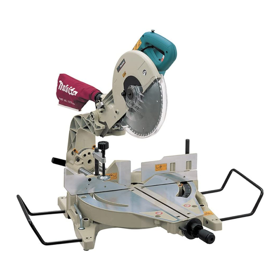
Slide compound saw
Hide thumbs
Also See for LS1214:
- Instruction manual (144 pages) ,
- Parts breakdown (5 pages) ,
- Instruction manual (32 pages)
Table of Contents
Advertisement
Advertisement
Table of Contents

Related Manuals for Makita LS1214


Summary of Contents for Makita LS1214
- Page 1 Slide Compound Saw MODEL LS1214 MODEL LS1214F I N S T R U C T I O N WARNING: For your personal safety, READ and UNDERSTAND before using. SAVE THESE INSTRUCTIONS FOR FUTURE REFERENCE. w w w . m a k i t a t o o l s . c o m...
-
Page 2: Specifications
SPECIFICATIONS Model ... LS1214/LS1214F Blade diameter ... 305 mm (12”) Hole diameter... 25.4 mm (1”) Max. Miter angle...Left 47° , Right 52° Max. Bevel angle... Left and Right 45° Max. Cutting capacities (H x W) Miter angle 0° 45° (left and right) (right)*71 mm x 175 mm 52°... -
Page 3: General Safety Precautions
For Your Own Safety Read Instruction Manual Before Operating Tool Save it for future reference GENERAL SAFETY PRECAUTIONS (For All Tools) 1. KNOW YOUR POWER TOOL. Read the owner’s manual carefully. Learn the tool’s applications and limitations, as well as the specific potential hazards peculiar to it. - Page 4 19. CHECK DAMAGED PARTS. Before further use of the tool, a guard or other part that is damaged should be carefully checked to determine that it will operate properly and perform its intended function - check for alignment of moving parts, binding of moving parts, breakage of parts, mount- ing, and any other conditions that may affect its operation.
-
Page 5: Additional Safety Rules
ADDITIONAL SAFETY RULES DO NOT let comfort or familiarity with product (gained from repeated use) replace strict adherence to slide compound saw safety rules. If you use this tool unsafely or incorrectly, you can suffer serious personal injury. 1. Wear eye protection. -
Page 6: Save These Instructions
20. Be sure that the blade does not contact the turn base in the lowest position. 21. Hold the handle firmly. Be aware that the saw moves up or down slightly during start-up and stopping. 22. Make sure the blade is not contacting the workpiece before the switch is turned on. - Page 7 INSTALLATION 001564 1. Stopper pin 001531 1. Bolt FUNCTIONAL DESCRIPTION 002016 1. Blade guard Bench mounting When the tool is shipped, the handle is locked in the lowered position by the stopper pin. Release the stopper pin by lower- ing the handle slightly and pulling the stopper pin. This tool should be bolted with four bolts to a level and stable surface using the bolt holes provided in the tool’s base.
- Page 8 Do not remove spring holding blade guard. If guard becomes discolored through age or UV light exposure, con- tact a Makita service center for a new guard. DO NOT DEFEAT OR REMOVE GUARD. Positioning kerf board This tool is provided with the kerf boards in the turn base to minimize tearing on the exit side of a cut.
- Page 9 004066 1. Adjusting bolt 2. Turn base 001540 1. Top surface of turn base 2. Periphery of blade 3. Guide fence 001562 1. Adjusting screw 2. Stopper arm 001541 1. Lock lever 2. Grip 3. Pointer 4. Miter scale Maintaining maximum cutting capacity This tool is factory adjusted to provide the maximum cutting capacity for a 305 mm (12”) saw blade.
- Page 10 004056 1. Lever 001543 1. Arm 2. Lever 3. Pointer 4. Bevel scale 001551 1. Lock-off button 2. Handle 3. Switch trigger Adjusting the bevel angle To adjust the bevel angle, loosen the lever at the rear of the tool counterclockwise. Unlock the arm by pushing the handle somewhat strongly in the direction that you intend to tilt the saw blade.
- Page 11 NEVER use the tool if it runs when you simply pull the switch trigger without pressing the lock-off button. Return tool to a Makita service center for proper repairs BEFORE further usage. •...
- Page 12 Always be sure that the tool is switched off and unplugged before installing or removing the blade. • Use only the Makita socket wrench provided to install or remove the blade. Failure to do so may result in overtightening or insufficient tightening of the hex bolt.
- Page 13 002020 1. Blade case 2. Arrow 3. Shaft lock 4. Hex bolt 5. Socket wrench 002021 1. Blade case 2. Arrow 3. Saw blade 4. Arrow 004058 1. Inner flange 2. Spindle 3. Ring 4. Saw blade 5. Outer flange 6.
- Page 14 NOTE: If you connect a Makita vacuum cleaner to your saw, more efficient and cleaner operations can be performed. Securing workpiece WARNING: •...
- Page 15 005593 1. Sub-fence 005594 1. Sub-fence 005595 1. Sub-fence R 2. Screws Sub-fence This tool is equipped with the sub-fence. It should be posi- tioned as shown in the figure. However, when performing left bevel cuts, set it to the left position as shown in the figure CAUTION: •...
- Page 16 005597 1. Vise rod 2. Screw 3. Vise knob 4. Vise arm 5. Guide fence 005688 1. Sub-fence R 2. Screw 3. Rod 4. Vise rod 5. Vise arm 001550 1. Vise plate 2. Vise nut 3. Vise knob 005232 Vertical vise The vertical vise can be installed in two positions on either the left or right side of the guide fence.
- Page 17 001544 1. Holder OPERATION CAUTION: • Always rotate the vise nut to the right fully when securing the workpiece. Failure to do so may result in insufficient securing of the workpiece. This could cause the workpiece to be thrown, cause damage to the blade or cause the loss of control, which can result in PERSONAL INJURY.
- Page 18 002022 1. Knob 002023 1. Knob 1. Press cutting (cutting small workpieces) Workpieces up to 115 mm (4-1/2”) high and 75 mm (2- 15/16”) wide can be cut in the following way. Push the carriage toward the guide fence fully and tighten the knob clockwise to secure the carriage.
- Page 19 • Never perform the slide cut with the handle locked in the lowered position by pressing the stopper pin. • Never loosen the knob which secures the carriage while the blade is rotating. This may cause serious injury. 3. Miter cutting Refer to the previously covered “Adjusting the miter angle”.
- Page 20 001555 52˚ 45˚ 45˚ 38˚ 45˚ 45˚ 1. 52/38° type crown molding 2. 45° type crown molding 3. 45° type cove molding • Always set the sub-fence to the left position when performing left bevel cuts. 5. Compound cutting Compound cutting is the process in which a bevel angle is made at the same time in which a miter angle is being cut on a workpiece.
- Page 21 001556 (1) (2) (3) (4) Fig.A 1. Inside corner 2. Outside corner 001557 1. Inside corner 2. Outside corner There are crown and cove molding joints which are made to fit “Inside” 90° corners ((1) and (2) in Fig. A) and “Outside”...
- Page 22 In the case of left bevel cut Molding position in Fig. A 52/38˚ type For inside corner Left 33.9˚ For outside corner Molding Molding edge against position in Fig. A guide fence Ceiling contact edge should For inside be against guide fence. corner Wall contact edge should be against guide fence.
- Page 23 In the case of right bevel cut Molding position in Fig. A 52/38˚ type For inside corner Right 33.9˚ For outside corner Molding Molding edge against position in Fig A guide fence Wall contact edge should be For inside against guide fence. corner Ceiling contact edge should be against guide fence.
- Page 24 000031 Ceiling 52˚ 38˚ Wall to Crown Molding Angle: 52/38 degrees Wall Angle Bevel Angle Miter Angle (deg.) (deg.) (deg.) 43.0 46.8 42.8 46.3 42.5 45.7 42.2 45.1 41.9 44.6 41.7 44.0 41.4 43.5 41.1 42.9 40.8 42.4 40.5 41.9 40.2 41.3 39.9...
- Page 25 000032 Ceiling 45˚ 45˚ Wall to Crown Molding Angle: 45 degrees Wall Angle Bevel Angle Miter Angle (deg.) (deg.) (deg.) 37.8 50.8 37.5 50.2 37.3 49.6 37.1 49.1 36.8 48.5 36.6 48.0 36.4 47.4 36.1 46.9 35.9 46.4 35.6 45.8 35.4 45.3 35.1...
- Page 26 001558 Fig. B 1. Crown molding stopper L 2. Crown molding stopper R 3. Turn base 001559 Fig. C 1. Crown molding stopper L 2. Crown molding stopper R 3. Turn base 001560 1. Guide fence 2. Crown molding 3. Crown molding stopper 4.
- Page 27 001844 1. Vise 2. Spacer block 3. Guide fence 4. Aluminum extrusion 5. Spacer block 004073 1. Aluminum extrasion 2. Guide fence 3. Spacer blocks 4. Horizontal vise 7. Cutting aluminum extrusion When securing aluminum extrusions, use spacer blocks or pieces of scrap as shown in the figure to prevent deformation of the aluminum.
- Page 28 001563 1. Cut grooves with blade CAUTION: • Use straight wood of even thickness as the wood facing. • When cutting workpieces from 115 mm (4 -1/2”) to 120 mm (4 - 3/4”) high, use a wood facing to prevent a portion of the workpiece near the guide fence from being left uncut.
- Page 29 001564 1. Stopper pin 002025 MAINTENANCE 001566 1. Guide fence 2. Hex bolts Carrying tool Make sure that the tool is unplugged. Secure the blade at 0° bevel angle and the turn base at right miter angle fully. Secure the slide poles after pulling the carriage toward you fully.
- Page 30 001567 1. Guide fence 2. Triangular rule 001568 1. Screw 2. Miter scale 3. Pointer 001569 1. Arm 2. Lever 3. Hex bolt 001570 1. Hex bolt Lower the handle fully and lock it in the lowered position by pushing in the stopper pin. Square the side of the blade with the face of the guide fence using a triangular rule, try-square, etc.
- Page 31 001571 1. Triangular rule 2. Saw blade 3. Top surface of turn base 001572 1. Bevel scale 2. Screws 3. Pointers 001573 1. Arm holder 2. Right 45° bevel angle adjusting bolt 3. Left 45° bevel angle adjusting bolt 004061 1.
- Page 32 004861 1. Screw 2. Kerf block 3. Guide fence 005598 Kerf block (optional accessory) CAUTION: • When using the kerf block, always cut at the same Miter angle. • When changing the Miter angle, use other kerf blocks. • When performing bevel cuts, never use the kerf block. Failure to do so splits the block, causing a serious injury to operator.
- Page 33 2. Screwdriver Pull out the Lamp Box keeping pushing lightly the upper posi- tion of it as illustrated on the left. Pull out the fluorescent tube and then replace it with Makita original new one. Replacing carbon brushes Remove and check the carbon brushes regularly. Replace when they wear down to the limit mark.
- Page 34 CAUTION: • These accessories or attachments are recommended for use with your Makita tool specified in this manual. The use of any other accessories or attachments might present a risk of injury to persons. Only use accessory or attachment for its stated purpose.
- Page 35 Memo...
- Page 36 Memo...
- Page 37 First-Class Postage Required Post Office will not deliver without proper postage. Makita U.S.A., Inc. 14930 Northam Street La Mirada, CA 90638-5753 Fold...
- Page 38 Paste 3. How did you learn about this product: Magazine From Dealer Newspaper Store Display Catalog 4. Most favored points are: Design Features Size Price Makita Brand MODEL NO. YEAR SERIAL NO. PHONE 20-29 30-39 40-49 Paste Paste Radio Exhibition...
- Page 39 Date Purchased When you need service: Send complete tool (prepaid) to one Dealer’s Name & Address of the Makita Factory Service Centers listed, or to an Authorized Makita Service Center. Be sure to attach a letter to the outside of Model No.
-
Page 40: Warranty Policy
MAKITA LIMITED ONE YEAR WARRANTY Warranty Policy Every Makita tool is thoroughly inspected and tested before leaving the factory. It is warranted to be free of defects from workmanship and materials for the period of ONE YEAR from the date of original purchase.
Need help?
Do you have a question about the LS1214 and is the answer not in the manual?
Questions and answers
slide is stuck
To fix a stuck slide on a Makita LS1214, follow these steps:
1. Clean the Slide Mechanism: Wipe off any chips, dust, or debris from the slide poles using a cloth.
2. Lubricate the Sliding Portions: Apply machine oil to the slide rails to reduce friction and prevent rust.
3. Check for Obstructions: Ensure that no foreign objects are blocking the movement of the slide.
4. Verify Proper Assembly: Make sure the carriage is fully inserted into the turn base when storing.
5. Seek Professional Repair if Needed: If the issue persists, contact a Makita Authorized Service Center for further inspection and repair.
These steps should help restore smooth operation of the slide mechanism.
This answer is automatically generated
Hi I have a LS1214 saw and I need a drawing of how the guard is re assembled please Thanks