Table of Contents
Advertisement
Quick Links
IMPORTANT:
•
• The glass tube will be extremely
hot when it is working so never
try to touch it and keep children
away.
• Turn off the appliance
immediately if it starts raining
and never use it while it is
raining as the glass tube may
break when it comes in contact
with water.
• Never splash any liquid onto
the glass tube when the
appliance is on.
• Always ensure the appliance
stands on a flat, firm surface as
the glass tube may break if the
appliance falls over.
• Never use the appliance if the
glass tube has any cracks or
damage.
Important: The installer or seller must leave these instructions with the consumer.
4782-07/17
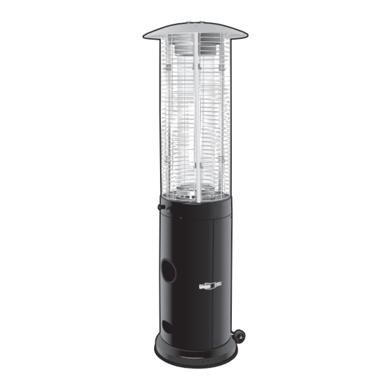
Blaze Outdoor Heater
Model No. GM124-028
Retain these instructions for future use.
FOR YOUR SAFETY
If you smell gas:
1. Shut off the gas to the
appliance.
2. Extinguish any open flame.
3. If odour continues,
immediately call your gas
supplier.
Do not store or use gasoline
or other flammable vapour and
liquids in the vicinity of this or any
other appliance.
WARNING:
Improper installation, adjustment,
alteration, service or maintenance
can cause injury or property
damage.
Read the instructions thoroughly
before installing or servicing this
equipment.
FOR OUTDOOR USE
ONLY
OPERATES ON
LPG/ULPG
Advertisement
Table of Contents

Related Manuals for Gasmate Blaze


Summary of Contents for Gasmate Blaze
- Page 1 Blaze Outdoor Heater Model No. GM124-028 IMPORTANT: FOR YOUR SAFETY • • The glass tube will be extremely If you smell gas: hot when it is working so never 1. Shut off the gas to the try to touch it and keep children appliance.
-
Page 2: Installation
Installation, Operation and Maintenance Instructions INSTALLATION Combustible materials are considered to be wood, Important Safety Rules: compressed paper, plant fibres, plastic, plexiglas or This appliance must only be used in a well ventilated other materials capable of being ignited and burned. area. - Page 3 The hose assembly should be properly located out of Reconnect the regulator to the gas cylinder. pathways where people may trip over it. The hose Leak test the connection using a soapy water solution. must be protected from contact with hot or sharp Ensure no bubbles appear before proceeding.
- Page 4 BLAZE Heater - For Outdoor Use Only Minimum Clearance from Combustible Surfaces*: 650mm Glass Tube Burner head Cylinder housing 535mm *Combustible materials are considered to be wood, compressed paper, plant fibres, plastic or other materials that are capable of being ignited and burned.
-
Page 5: General Assembly
GENERAL ASSEMBLY Connecting & Disconnecting to Gas Source IMPORTANT: Before connecting and disconnecting appliance to gas source, make sure control knob is in ‘OFF’ position. CAUTION: When the appliance is not in use, the gas must be turned off at the cylinder. Familiarise yourself with the general information and safety guidelines located at the front of this manual. -
Page 6: Parts List
PARTS LIST Part Name Part Name Upper Reflector Mesh Guard Glass Tube Ring Body Support Burner Battery (AA) Cylinder Housing Upper Support Glass Tube Wheel Assembly HARDWARE AA. M5x12 Screw BB. M6x12 Screw CC. M8x16 Screw DD. M6 Lock Nut GG. Wrench x 2PCS x 10PCS x 3PCS x 10PCS x 1PC... - Page 7 ASSEMBLY INSTRUCTIONS Tools Required: 1 Phillips head screwdriver, 1 adjustable spanner. Step 1: Step 2: Flip the cylinder housing (D) upside down and attach the Attach the cylinder housing support (G) into the cylinder wheel assembly (J) to the base of the cylinder housing housing (D) using 1 M8 x 16 screw (CC) and 2 M5 x 12 (D) using 2 M8 x 16 screws (CC). screws (AA). Do not fully tighten to allow room for adjustment later in the assembly process. Step 3: Step 4: Remove the preassembled M5 screws from the upper Align the holes at the bottom of the burner (C) to the support (I), then slide the 3 upper support into the slots top of the cylinder housing (D) - position to have the...
- Page 8 ASSEMBLY INSTRUCTIONS Step 5: Step 6: Remove the 3 preassembled screws from the top of the Place the glass tube (E) into the top of the glass tube burner (C). Attach the glass tube ring (B) to the top ring (B). of the burner (C) using the 3 screws removed at the beginning of this step. Be sure to fully tighten. Step 7: Step 8: Remove the 3 preassembled screws from the upper Attach the 3 mesh guards (F) onto the hooks at the top supports (I). Place the upper reflector (A) onto the top of the upper supports (I).
- Page 9 ASSEMBLY INSTRUCTIONS Step 9: Step 10: Open the door from the cylinder housing (D) and place Ensure cylinder valve is in its full off position. Check for the LPG cylinder (not included) into the preassembled any damage to either the cylinder connection or the hose. cylinder support. Tighten the belt to ensure the cylinder NEVER attempt to use damaged equipment. Attach the ASSEMBLY INSTRUCTIONS ASSEMBLY INSTRUCTIONS is fully secure.
-
Page 10: Troubleshooting
TEST FIRING THE APPLIANCE TEST FIRING THE APPLIANCE Test fire appliance, following the lighting instructions on. Leak test all gas connections with soapy water. Soap bubbles indicate gas leakage. DO NOT use a match to test for gas leaks. WARNING: White smoke may appear around the burner during the first minute of the initial firing. TROUBLE SHOOTING Problem Possible Causes... -
Page 11: Safe Appliance Locations
The following figures are diagrammatical representations of outdoor areas. Rectangular areas have been used in these figures - the same principles apply to any other shaped area. Distributed by: Aber, Hamilton, N.Z. Gasmate ® is a registered trademark of: Sitro Group Australia Pty Ltd www.gasmate.com.au www.gasmate.co.nz Aber, Hamilton, N.Z. www.gasmate.co.nz...
Need help?
Do you have a question about the Blaze and is the answer not in the manual?
Questions and answers