Table of Contents
Advertisement
Quick Links
Advertisement
Table of Contents

Related Manuals for Sony PVM-L1700


Summary of Contents for Sony PVM-L1700
- Page 1 LCD VIDEO MONITOR PVM-L1700 OPERATION MANUAL [English] 1st Edition (Revised 2)
- Page 2 WARNING Before operating the unit, please read this manual thoroughly and retain it for future reference. To reduce the risk of fire or electric shock, do not Important Safety Instructions expose this apparatus to rain or moisture. To avoid electrical shock, do not open the •...
- Page 3 TV studio). Dette utstyret kan kobles til et IT-strømfordelingssystem. Apparatet må tilkoples jordet stikkontakt The manufacturer of this product is Sony Corporation, 1- 7-1 Konan, Minato-ku, Tokyo, Japan. Suomessa asuville asiakkaille The Authorized Representative for EMC and product Laite on liitettävä...
- Page 4 • EN55103-1: Elektromagnetische Verträglichkeit électromagnétique suivant: E4 (environnement EMC (Störaussendung) contrôlé, ex. studio de télévision). • EN55103-2: Elektromagnetische Verträglichkeit (Störfestigkeit) Le fabricant de ce produit est Sony Corporation, 1-7-1 Für die folgende elektromagnetische Umgebung: E4 Konan, Minato-ku, Tokyo, Japon. (kontrollierter EMV-Bereich, z.B. Fernsehstudio).
- Page 5 Der Hersteller dieses Produkts ist Sony Corporation, 1-7-1 Konan, Minato-ku, Tokyo, Japan. Der autorisierte Repräsentant für EMV und Produktsicherheit ist Sony Deutschland GmbH, Hedelfinger Strasse 61, 70327 Stuttgart, Deutschland. Bei jeglichen Angelegenheiten in Bezug auf Kundendienst oder Garantie wenden Sie sich bitte an die in den separaten Kundendienst- oder Garantiedokumenten aufgeführten...
-
Page 6: Table Of Contents
Table of Contents Chapter 1 Overview Precautions ................9 On Safety ..................9 On Installation ................9 Handling the LCD Screen ............9 With Protection Plate Installed........... 9 On Cleaning................9 On Repacking ................10 On Rack Mounting ..............10 Functions Supported in Software Version 1.1 ....11 Features ................ - Page 7 Color Temperature (White Balance) Adjustment.....32 Brightness/Contrast Adjustment ..........32 Chapter 3 Menu Basic Menu Operations............34 Menu Operation Buttons............34 Displaying the Menu..............35 Setting or Adjusting in the Menu Operation......35 Entering the Channel Number ..........37 Aborting Menu Operation............37 Menu Structure ..............38 Adjustment Menu..............45 Overview...................45 Menu Function and Operation ..........45 Input Configuration Menu ...........51...
- Page 8 Selecting the Native Scan/Scan Mode ......85 Displaying Two Signals on One Screen (Picture&Picture) ............ 86 Magnifying the Picture (Pixel Zoom) ......... 87 Displaying the Picture in Black Detail Mode ....88 Capturing the Picture of the HD Signal (HD Frame Capture) ..........89 Displaying the Area Marker or Aspect Marker ....
-
Page 9: Chapter 1 Overview
Overview Chapter of pixels may be “stuck”, either always off (black), Precautions always on (red, green, or blue), or flashing. In addition, over a long period of use, because of the physical characteristics of the liquid crystal display, such “stuck” pixels may appear spontaneously. -
Page 10: On Repacking
0 to 35 °C (32 to 95°F). If you have any questions about this unit, please contact your Sony service representative. Precautions... -
Page 11: Functions Supported In Software Version 1.1
Functions Supported in Software Version 1.1 The following new functions are supported for Version 1.1 of the PVM-L1700. Menu Supported function Reference page • Checkerboard Simultaneous display or left/right switching display of 66, 69, 81, 92 the left and right 3D video signals is available by •... -
Page 12: Features
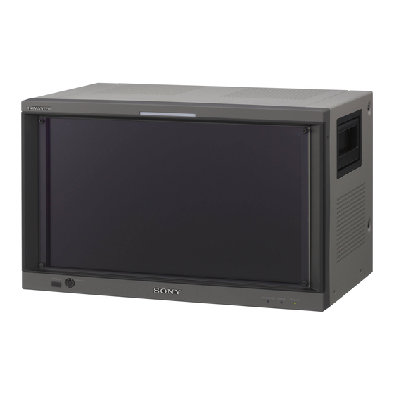
Black frame insertion display mode Motion blur caused by the holding-type display of the LCD The PVM-L1700 is 17-inch LCD Video Monitor. This is is decreased by inserting the black frame between the suitable for television stations or video production houses, picture frames in double frame rate (100/120Hz) operation where precise image reproduction is required. - Page 13 Audio level meter/time code display function For the operation, see “Displaying the Area Marker or Aspect Marker” on page 90. Audio level of the embedded audio and time code signals superimposed on the SDI signals are displayed by Scan selection/Native scan display function installing the optional input adaptor (BKM-250TG).
-
Page 14: Options
Includes a decoder for analog component signals and BKM-16R Monitor Control Unit analog RGB signals. Input connector for one channel is The BKM-16R is a controller of the PVM-L1700 and you equipped. can control multiple monitors from one controller. BKM-243HS HD/D1-SDI Input Adaptor In this manual, the BKM-16R is referred to as the Includes a decoder for serial digital component signals. -
Page 15: Input/Output Connector And Adaptor
BKM-229X: This equipment may not work correctly or you may not be satisfied with the performance if designated input adaptors are not installed. BKM-243HS: This equipment may not meet the requirements of the electromagnetic interference standard or work correctly, or you may not be satisfied with the performance if designated input adaptors are not installed. - Page 16 Input adaptor BKM- BKM- BKM- BKM- BKM- 220D 227W 229X 243HS/ 250TG Input signal 244CC Component 525/ Single-link HD-SDI Dual-link HD-SDI a(2) Single-link 3G-SDI Composite NTSC Composite PAL Composite PAL-M Composite SECAM Y/C NTSC Y/C PAL Y/C PAL-M Y/C SECAM YPbPr 525i/625i RGB 525i/625i YPbPr/RGB...
-
Page 17: Location And Function Of Parts
Location and Function of Parts Front Panel 1 Tally lamp 6 OPTION B connector 2 OPERATE lamp 5 OPTION A 3 STATUS lamp connector 4 OVER RANGE lamp a Tally lamp Notes With factory settings, the tally lamp lights when pins No. 8 and No. - Page 18 The OVER RANGE lamp, STATUS lamp or OPERATE lamp on the front panel may show an error, warning or operation mode while the monitor is being operated. Error display If the error is shown, please contact your Sony representative. OVER STATUS...
-
Page 19: Rear Panel
Rear Panel 1 AC IN connector 2 ON/OFF switch 3 DC IN 24 - 28V connector q; Input option slots 4 DC 5V OUT connector 9 HDMI input connector 5 LAN (10/100) connector 8 DVI-D input connector 6 NETWORK switch 7 PARALLEL REMOTE connector a AC IN connector (3-pin) Connect to the DC 5V/12V IN connector of the controller... - Page 20 Buchse haben könnte. Folgen Sie den Anweisungen für To monitor the DVI signal of SXGA or higher resolution, diese Buchse. use the cable within 3 m (118 inches) in length. f NETWORK switch i HDMI input connector LAN: To connect to the network. Inputs the HDMI signal.
-
Page 21: Chapter 2 Preparations
Preparations Chapter Environments of the Installation Location Illumination environments Viewing angle The apparent color reproduction on the monitor is greatly The ideal viewing angle is within 5 degrees (up/down/left/ affected by ambient light or glare. right) off the center of the monitor screen when the The LCD device controls the brightness by moving LCD operator views the entire monitor screen. -
Page 22: Installing An Input Adaptor
Installing an Input Adaptor Each input adaptor can be installed in any input option slot on the rear panel. Caution When you install the following input adaptors to this equipment, use those with the serial numbers given below. • BKM-220D with serial number 2100001 or higher •... -
Page 23: Removing The Protection Plate
Removing the Protection Example of Dual-link cable connection Plate OPTION 3 and 4 OPTION 1 and 2 The protection plate is installed on the monitor to protect the LCD panel at the factory. You can remove the protection plate when the picture differs in color from that without the protection plate and/ or when there is more reflection of light than without. -
Page 24: Mounting The Unit In A Rack
Remove the four feet from the bottom of the unit. OUT connector. Attach the rack mount brackets to each side of the unit with the rack mount attachment screws. PVM-L1700 Rack mount bracket Plug the male connector into Rack mount the monitor. -
Page 25: Connecting The Controller (Bkm-16R)
Turn off the ON/OFF (power) switch of the monitor Connecting the Controller (BKM- (OFF) before connecting the units. 16R) Set the NETWORK switches of the monitor and the controller to PEER TO PEER. Monitor Connect the LAN (10/100) connector of the monitor and the LAN (10/100) connector of the controller by using the SMF-700 or the cable supplied with the BKM-39H, or a 10BASE-T/100BASE-TX straight... - Page 26 Monitor Monitor LAN (10/100) LAN (10/100) NETWORK NETWORK connector connector PEER TO PEER TO PEER PEER Set to LAN. Set to LAN. AC adaptor (supplied with the BKM-16R) Switching hub (recommended: with AUTO MDI/MDI-X function) LAN (10/100) DC 5V/12V IN connector connector Controller (BKM-16R)
-
Page 27: Turning On The Power
Turning on the Monitor Turning on the Power Press the ON/OFF (power) switch on the rear panel (ON) to turn on the power. Connecting to Power When you turn on the monitor for the first time after purchasing it, the Select Area screen is displayed. Select the area where you intend to use this monitor. -
Page 28: Settings
Settings Selecting the Area When you turn on the monitor for the first time after ENTER button purchasing it, select the area where you intend to use this monitor from among the options. UP/DOWN buttons When the area is selected, the menu item settings suitable Ent button for the selected area are applied. -
Page 29: Setting For The Lan To Connect The Multiple Units
If 4 Asia Except Japan is selected: After saving and reflecting the setting, you can change the setting with the menu. • Color Temp (color temperature) (page 53) • Setup Level (NTSC Setup Level: page 55, Betacam Select Area NTSC area Setup Level: page 55) Asia Except Japan •... -
Page 30: Selecting The Monitor (Designation Of The Monitor Or Group Id Number)
Set the different monitor ID number to each monitor Press the corresponding button to select the connection and if necessary, group ID number. mode. You can use the numbers 1 to 99 as a monitor ID SINGLE button: Selects single connection mode. number or group ID number. -
Page 31: Setting The Display Mode Of The Picture
Adjusting Before adjusting The monitor must be warmed up sufficiently. To perform stable color reproduction, turn on the power of the monitor, display the white signal and leave it in this state for more than 30 minutes. About monitor adjustment The monitor is used as a measuring instrument and is required to faithfully reproduce the input signal. -
Page 32: Color Temperature (White Balance) Adjustment
Automatic adjustment (recommended) Color Temperature (White Balance) Adjustment Input the reference color-bar signal to the monitor. Select Auto in the Picture Adj menu of the Adjustment You can adjust manually or automatically with a specified menu and perform the automatic adjustment of the color temperature probe. - Page 33 The following are explained as the example when the multi format color-bar signal is used for adjustment. Select the Manual Adjust menu (page 46) in the Picture Adj menu of the Adjustment menu. Adjust the –2%, 0% and +2% ranges or the 0%, +2% and +4% ranges of the PLUGE signal section of the color-bar with the BRIGHT knob.
-
Page 34: Chapter 3 Menu
Menu Chapter Basic Menu Operations Menu Operation Buttons The menu is operated using the menu operation buttons on the controller (BKM-16R, optional). Controller (BKM-16R) 1 UP/DOWN buttons 2 MENU button 3 ENTER button 4 PHASE knob REMOTE INPUT CHROMA CONTRAST PHASE BRIGHT SINGLE... -
Page 35: Displaying The Menu
The current settings are displayed in place of the x Displaying the Menu marks on the illustrations of the menu screen. Press the MENU button. iInput Configuration The main menu is displayed on the screen. CH01 Format Slot No: xxxxx Input No: xxxxx MENU... - Page 36 When selecting in setting mode The cursor moves to the setting value and the monitor enters in setting mode. Using the UP or DOWN button or PHASE knob, select Display example the desired item and press the ENTER or Ent button. The cursor moves to the setting value and the monitor iInput Configuration enters in setting mode.
-
Page 37: Entering The Channel Number
When you press the UP button or turn the PHASE knob 094: Five-step gray scale signal clockwise, the characters and symbols appear in the 095: Ramp signal sequence shown below. 096: color-bar signal Capital letters (A t B t ..t Y t Z) t Lower- 097: 0% black signal case letters (a t b t .. -
Page 38: Menu Structure
Menu Structure For details of each menu, see the page in parentheses. Adjustment menu (page 45) Main menu Level 1 Level 2 Level 3 Level 4 Adjustment Picture Adj Auto Auto Adjust Color Bar Restore Factory Data Status Slot No Format Matrix Manual Adjust... - Page 39 Input Configuration menu (page 51) Main menu Level 1 Level 2 Level 3 Level 4 Input Configuration Format 3G/HD/SD-SDI Dual Link HD-SDI Composite Component HDMI Slot No Input No Screen Aspect Sync Mode HDMI Auto Color Temp Picture Preset Matrix/Gamma DVI/HDMI Computer HDMI Auto Color Gamut...
- Page 40 Display Function menu (page 59) Main menu Level 1 Level 2 Level 3 Level 4 Display Function Marker Setting Aspect Blanking Aspect Blanking Mode Aspect Marker Aspect Marker Aspect Mode Aspect Line Color Bright Area Marker 1 Area Marker 1 Aspect Mode Aspect Area Size...
- Page 41 Main menu Level 1 Level 2 Level 3 Level 4 Capture Load Rename Delete Internal Signal Function Switch Scan Mode Native Scan 16:9 H Delay V Delay External Sync Comb Aperture Mono Blue Only R Off G Off B Off Chroma Up Black Frame Insertion Interlace...
- Page 42 System Configuration menu (page 67) Main menu Level 1 Level 2 Level 3 Level 4 System Configuration Network Monitor ID Group ID Network Setting IP Address Subnet Mask Default Gateway Address SNMP Setting Contact Name Location Trap Mode Trap Address Setting Trap Address Status Reset Mode/Address Community...
- Page 43 File Management menu (page 74) Main menu Level 1 Level 2 Level 3 Level 4 File Management Save To Memory Stick Copy From Other Monitor Monitor ID Memory Stick Delete Memory Stick Data Maintenance Back Up System Data Restore System Data Status menu (page 76) Main menu Level 1...
- Page 44 Controller menu (page 78) / Key Protect menu (page 82) Main menu Level 1 Level 2 Level 3 Level 4 Controller Network Network Setting IP Address Subnet Mask Default Gateway Address SNMP Setting Contact Name Location Trap Mode Trap Address Setting Trap Address Status Reset Mode/Address Authentication...
-
Page 45: Adjustment Menu
Adjustment Menu Overview Adjusts the picture, color temperature, etc. Note When Adjustment is selected, the following menu is displayed. This menu is not selectable in the following cases: • When Side by Side is set to On iAdjustment Picture Adj Color Temp Adj Position Adj Menu Function and Operation... - Page 46 Menu Function and operation ([ ]: factory setting) Color Bar Sets the color-bar signal to input. [Full Field 8]: 100% full-field 8-color bars (white, yellow, cyan, green, magenta, red, blue and black) SMPTE: SMPTE standard color bars EIA: EIA standard color bars (effective for 480/60i and 575/50i signals only) Multi Format: Color bars standardized by SMPTE RP219/ARIB STD-B28 Restore Factory Data Resets the automatic adjustment data of chroma, phase, matrix and signal level to the default...
- Page 47 Menu Function and operation ([ ]: factory setting) Color Temp Adj Adjusts the color temperature. When the item is selected, the color temperature data to be adjusted is displayed. When D93 or D65 data is changed, they are displayed as D93* or D65*. To change the color temperature data to be adjusted, select D93, D65, User1, User2, User3, User4 or User5 in the Color Temp menu of the Input Configuration menu.
- Page 48 Menu Function and operation ([ ]: factory setting) Contrast Hold Sets whether or not to adjust the color temperature and contrast (backlight) at the same time. Off: Contrast is adjusted. [On]: Contrast is not adjusted. Auto Adjusts the color temperature automatically by using an optional probe. When the item is selected, the color temperature data to be adjusted is displayed.
- Page 49 Eye-One Pro. Before adjusting the color temperature automatically, start the software for adjusting the color temperature. For the software for adjusting the color temperature, please contact your Sony representative. For more information about the cable specification required and about the connection, see “Connection Cable Specifications for Color Temperature Probes”...
- Page 50 Menu Function and operation ([ ]: factory setting) Restore Factory Data Resets the color temperature to the default setting. You cannot select this when the setting is the default value. The following message appears to confirm the data reset operation. Restore factory data? OK: To reset the data, press the ENTER (Ent) button.
-
Page 51: Input Configuration Menu
Input Configuration Menu Overview This menu is used for pertaining data to the input signals. When Input Configuration is selected, the following menus are displayed. iInput Configuration iInput Configuration iInput Configuration CH01 CH01 CH01 Format Marker Preset: xxxxx Copy From Slot No: xxxxx H Shift Offset:... - Page 52 Menu Function and operation ([ ]: factory setting) When BKM-250TG is installed 3G/HD/SD-SDI Auto: Changes the format automatically according to the Sampling Structure, Bit Depth, Picture and transport scanning method information for Payload ID of SMPTE-352M standard superimposed on the input signals. Note You can confirm the Payload ID information and the signal format status of the current monitor in “SDI Payload ID Status”...
- Page 53 Menu Function and operation ([ ]: factory setting) Slot No Enters the option slot number. You can select from Option1 to Option4, Option1&2 or Option3&4. Adaptor and the item to be selected Option1 to Option4 • When the BKM-250TG is installed and Format is set to 3G/HD/SD-SDI Auto or 4:2:2 YPbPr 10bit, 4:4:4 YPbPr 10bit, 4:4:4 RGB 10bit, 4:4:4 YPbPr 12bit or 4:4:4 RGB 12bit of 3G-SDI •...
- Page 54 Note When you select xvYCC 709 or xvYCC 601, set Emulation (page 55) to PVM-L1700 Native in the Color Gamut menu of the Input Configuration menu to display the extended color gamut area.
- Page 55 Color Gamut As the PVM-L1700 is equipped with the wider color space backlight, the signal can be displayed (emulation) in the color gamut (color space and gamma) selected in the Emulation menu.
- Page 56 Menu Function and operation ([ ]: factory setting) RGB Range Sets the quantization range of the DVI or HDMI input signal. You can select when Format is set to DVI Video, DVI Computer or HDMI. DVI Video Sets the display mode for the DVI Video signal. Full: 0 (black level) to 255 (white level) (8bit) [Limit]: 16 (black level) to 235 (white level) (8bit) DVI Computer...
-
Page 57: Display Setting Menu
Transmission gamma of IEC 61966-2-4 standards (xvYCC) Notes • When you select xvYCC, set Emulation (page 55) to PVM-L1700 Native in the Color Gamut menu of the Input Configuration menu to display the extended color gamut area. • When the quantization range of the DVI signal or HDMI signal is Full, the internal fixed value of the transmission gamma is applied. - Page 58 Menu Function and operation ([ ]: factory setting) Memory Stick Copies data in the “Memory Stick”. When the item is selected, the file names in the source “Memory Stick” are displayed. When the file is selected, you can select from User1, User2, User3, User4 or User5. Native Scan Mode Sets the native scan mode.
-
Page 59: Display Function Menu
Display Function Menu Overview This menu is used to set the function related to the picture display. When Display Function is selected, the following menu is displayed. iDisplay Function Marker Setting P&P Setting Pixel Zoom Setting Black Detail Setting B Capture Internal Signal Function Switch... - Page 60 Menu Function and operation ([ ]: factory setting) Bright Sets the luminance of the aspect marker. You can select from [90IRE] (bright) or 40IRE (dark). Area Marker 1 Sets the area marker 1. Area Marker 1 Sets whether or not to display the area marker 1 when the MARKER button is pressed (Off or [On])*.
- Page 61 Menu Function and operation ([ ]: factory setting) Example: Area Size 80%, Aspect Mode 16:9 or 4:3 With 16:9 Aspect Mode 16:9 Aspect Mode 4:3 With 4:3 Aspect Mode 16:9 Aspect Mode 4:3 Line Sets the thickness of the area marker 1. You can select from [Thick] (thick) or Thin (thin).
- Page 62 Menu Function and operation ([ ]: factory setting) Other Monitor Copies data from another monitor. Monitor ID Enter the ID number of the source monitor. When the NETWORK switch is set to PEER TO PEER, this is not selectable. When the ID number is entered, you can select from Marker1, Marker2, Marker3, Marker4 or Marker5.
- Page 63 Menu Function and operation ([ ]: factory setting) Internal Signal Selects the internal signal display. You can select from PLUGE, Gray (20% gray signal), White (100% white signal), 5 step (5 step gray scale signal), Ramp, Color Bars or Black (0% black signal). To cancel the internal signal, select one from the channel numbers 1 to 30 with the numeric buttons of the controller.
- Page 64 Menu Function and operation ([ ]: factory setting) External Sync Sets whether or not to select external sync mode ([Off] or On) when the analog component signal or analog RGB signal format is input. When On is selected, the signal to be displayed is synchronized with the sync signal input to the SYNC connector (External Sync).
- Page 65 Menu Function and operation ([ ]: factory setting) Marker Sets whether or not to display all markers ([Off] or On). Note The marker is not displayed in the following cases: • When the input signal has no sync signal • When the internal signal is displayed •...
- Page 66 Menu Function and operation ([ ]: factory setting) ALM Hold Reset When the item is selected, the peak hold of the audio level meter is canceled. Notes • The ALM Hold Reset is not selected in the following cases: – When the option slot number in which the BKM-250TG is installed is not selected in Slot No of the Input Configuration menu –...
-
Page 67: System Configuration Menu
System Configuration Menu Overview This menu is used to set the system such as the network, parallel remote control function, etc. When System Configuration is selected, the following menu is displayed. iSystem Configuration Network Parallel Remote Power On Screen Set Password Date/Time Scan Mode Skip:... - Page 68 SDCP/SDAP Community Sets the SDCP/SDAP community name. When the item is selected, you can enter the community name (four characters). SONY: SONY is entered as a community name. New Name: Enter a new name. SDCP Port No Sets the SDCP port number.
- Page 69 Menu Function and operation ([ ]: factory setting) 1 Pin to 8 Pin Assigns the function to each pin of the PARALLEL REMOTE connector when Parallel Remote is set to On. 1 Pin: [CH01] 2 Pin: [CH02] 3 Pin: [External Sync] 4 Pin: [Mono] 5 Pin: [Marker] 6 Pin: [unused]...
- Page 70 Menu Function and operation ([ ]: factory setting) Power Sets the status of the monitor when the main power is turned on or the power is turned on by remote operation. Standby Mode Sets the status when the ON/OFF (power) switch is turned on. [Off]: Operation mode On: Standby mode Power On Status...
- Page 71 Menu Function and operation ([ ]: factory setting) Type Sets the closed caption type. [Auto1]: Select to set to 608(VBI) when the SD-SDI signal is input or 708 when the HD- SDI signal is input. Auto2: Select to set to 608(VBI) when the SD-SDI signal is input or 608(708) when the HD-SDI signal is input.
- Page 72 Menu Function and operation ([ ]: factory setting) Apply Password Sets whether or not to apply the password to each menu (Yes or [No]). Adjustment Yes: Apply the password. [No]: Not apply the password. Input Configuration Yes: Apply the password. [No]: Not apply the password.
- Page 73 Menu Function and operation ([ ]: factory setting) FPGA Upgrade Upgrades the FPGA data of the monitor. Maintenance The menu for the Sony service representative is displayed. System Configuration Menu...
-
Page 74: File Management Menu
File Management Menu Overview The system data is saved, copied and deleted. When File Management is selected, the following menu is displayed. iFile Management Save To Copy From Delete Data Maintenance Menu Function and Operation Menu Function and operation ([ ]: factory setting) Save To Saves the data in the “Memory Stick”. - Page 75 Menu Function and operation ([ ]: factory setting) Memory Stick Selects the data in the source “Memory Stick”. When the item is selected, the file names in the “Memory Stick” are displayed. When the item is selected, you can select the data to be copied. All: Copies all data.
-
Page 76: Status Menu
Status Menu Overview This menu is used to view general data about the monitor status, current channel, etc. When Status is selected, the following menus are displayed. iStatus iStatus CH Status Model Name: xxxxx Serial No: xxxxx Slot Status Software Version: xxxxx Option1 HD-SDI/D1 Option2 D1... - Page 77 Menu Function and operation ([ ]: factory setting) SDI Payload ID Status Displays the information of the Payload ID data superimposed on the SDI signal and current signal status of the monitor. When the option slot number in which the BKM-250TG is installed is selected in Slot No of the Input Configuration menu, the following is displayed.
-
Page 78: Controller Menu
Controller Menu Overview This menu is for the network setting and assigning the function to the function button of the controller. When Controller is selected, the following menu is displayed. iController Network Function Key Monitor ID Display: Controller Upgrade Menu Function and Operation Menu Function and operation ([ ]: factory setting) - Page 79 SDCP/SDAP Community Sets the SDCP/SDAP community name. When the item is selected, you can enter the community name (four characters). SONY: SONY is entered as a community name. New Name: Enter a new name. SDCP Port No Sets the SDCP port number.
- Page 80 Menu Function and operation ([ ]: factory setting) F1 to F16 The following functions are assigned. Scan Mode: Changes the scan mode of the picture. Native Scan: Displays the picture in native scan mode. 16:9: Changes the aspect ratio to 16:9, and when set to Off, the aspect ratio changes to 4:3.
- Page 81 Menu Function and operation ([ ]: factory setting) Area Marker1: An area marker 1 is displayed on the screen. Note When External Sync is set to On, the marker may not be shown in the correct position. Area Marker2: An area marker 2 is displayed on the screen. Note When External Sync is set to On, the marker may not be shown in the correct position.
-
Page 82: Key Protect Menu
Key Protect Menu Overview This menu is used to lock the data so that the setting is not changed by an unauthorized user. MENU Adjustment Input Configuration Display Setting Display Function System ConfigurationB File Management Status Controller Key Protect: Menu Function and Operation Menu Function and operation ([ ]: factory setting) -
Page 83: Selecting Display Mode
Operations Chapter For selecting the interlace display mode, set Native Selecting Display Mode Scan (page 63) to On in the Display Function menu or by pressing the NATIVE SCAN button of the controller. This monitor applies high-contrast to the picture and Set Interlace and Black Frame Insertion in the reproduces accurate color by displaying the interlace Function Switch menu (page 63) of the Display... -
Page 84: Setting The Display Of Native Scan Mode
Setting the Display of Native Scan Mode Displayed the whole picture of the H direction UP button DOWN button by sliding the picture About the native scan mode with the PHASE knob of the controller. You can set the picture display type for the native scan mode according to the input signal. -
Page 85: Selecting The Native Scan/Scan Mode
Over Scan: Over mode Selecting the Native For details on the Function Switch menu, see “Function Scan/Scan Mode Switch” (page 63) in the Display Function menu. Note You can select scan mode from a native scan, under scan (– The scan mode is not selectable in the following cases: 3%), normal scan (0%) and over scan (mask of 5% over •... -
Page 86: Displaying Two Signals On One Screen
* The function of Picture&Picture is assigned to the function button of the controller in the Function Key menu (page 79) Displaying Two Signals of the Controller menu. on One Screen Select the channel number and set the input signal to display as signal B. -
Page 87: Magnifying The Picture (Pixel Zoom)
Press the ENTER (Ent) button. Magnifying the Picture Part inside the cursor is magnified. You can move the position of the magnified picture (Pixel Zoom) with the PHASE knob or CHROMA knob. You can change the magnification ratio with the UP or DOWN button. -
Page 88: Displaying The Picture In Black Detail Mode
Zebra pattern display of the clipped portion Displaying the Picture in Black Detail Mode Zebra pattern Black detail mode display function You can reduce to dull black color by backlight leaking and precisely assess any parts with low color gradation. To end the black detail mode You can decrease the black level up to 40% of the normal Set the Black Detail Mode button of the controller to off, or... -
Page 89: Capturing The Picture Of The Hd Signal
To hide characters on the monitor, set the CHAR OFF Capturing the Picture of button to on. As the characters are hidden, it becomes easy to confirm the still picture. To display the the HD Signal (HD Frame characters, set the CHAR OFF button to off. Capture) Press the ENTER (Ent) button. -
Page 90: Displaying The Area Marker Or Aspect Marker
Displaying the Area Displaying the Audio Marker or Aspect Marker Level Meter The monitor is equipped with two area markers and center The audio level of the embedded audio signals marker as the safe area marker and aspect marker for superimposed on the SDI signals is displayed by installing confirming the picture angle. -
Page 91: Displaying The Time Code
Audio level Audio level Displaying the Time Code (dB) OVER The time code superimposed on the SDI signals is displayed by installing the optional input adaptor (BKM- 250TG). Note As the time code is superimposed on the video signal, the time code may be invisible partially because of the scan mode setting of the monitor. -
Page 92: Switching The Display Of The 3D Video Signal
Select Checkerboard display or L/R Switch display Switching the Display of with the function button* of the controller or in the Function Switch menu of the Display Function menu, the 3D Video Signal and set it to On. If the Checkerboard or L/R Switch function has been assigned to a pin of the PARALLEL REMOTE Left (L) and right (R) 3D video signals can be displayed on connector, set Parallel Remote to On in the System... -
Page 93: Copying The Setting Or Adjustment Value To Another
Press the ENTER (Ent) button. Copying the Setting or The data is saved in the “Memory Stick”. Adjustment Value to Notes Another Monitor • Data saving, copying and deleting using the “Memory Stick” is not available on BKM-15R or BVM-A14F5. •... -
Page 94: Assigning The Function On The Function Button
• When the unit is upgraded, use the AC power supply for B Off the monitor. Chroma Up To get the upgrade data Black Frame Insertion Contact your Sony representative. Interlace Pixel Zoom Marker Saving the Upgrade Data in a Aspect Marker “Memory Stick PRO”... -
Page 95: Upgrading The Monitor
“Procedure failure” is displayed in red. If this error message is displayed, contact Insert the “Memory Stick PRO” into the Memory Stick your Sony representative. insertion slot of the controller. Upgrading the Controller Select the Monitor Upgrade menu in the System Configuration menu (page 72). - Page 96 If this error message is displayed, It takes about 1 minute to upgrade the controller. contact your Sony representative. Exit the Controller Upgrade menu, select the REMOTE Controller Upgrade menu again, and confirm that the SINGLE version of the selected item has been upgraded.
-
Page 97: Appendixes
Appendixes Signal format Specifications Refer to “Available Signal Systems” (page 101) and “Available Signal Formats” (page 103). PC input DVI-D × 1 General HDCP correspondence LCD panel a-Si TFT Active Matrix Signal format Picture size 16.52 inches Refer to “DVI-D” (page 107) of Display area 365.76 (H) ×... - Page 98 TO RECORD CONTENT OF ANY TYPE. • Always verify that the unit is operating properly AC power cord (1) before use. SONY WILL NOT BE LIABLE FOR AC plug holder (1) DAMAGES OF ANY KIND INCLUDING, BUT Rack mount bracket (Left, right, each 1)
-
Page 99: Input Signals And Adjustable/Setting Items
Input Signals and Adjustable/Setting Items Input signal Analog DVI-D HDMI Item Component 3G/HD Video Computer (YPbPr) Composite HD YPbPr YPbPr RGB CONTRAST BRIGHT CHROMA × × × × × (*7) PHASE × × × × × × × × × ×... - Page 100 Input signal Analog DVI-D HDMI Item Component 3G/HD Video Computer (YPbPr) Composite HD YPbPr YPbPr RGB Black Frame Insertion See “Picture·Frame Display” on page 113. Interlace Black Detail Mode (*6) Audio Level Meter × × × × × × × ×...
-
Page 101: Available Signal Systems
Available Signal Systems Input adaptor Total lines Active lines Frame rate Scanning Aspect Display on the Signal system Standard per frame per frame (Hz) format ratio monitor Rec.ITU-R 720×576/50i 2:1 Interlace 16:9/4:3 575/50I BT.601 1440×576/50i* 2:1 Interlace 16:9/4:3 575/50I Rec.ITU-R 480/60I 720×487/59.94i 30/1.001... - Page 102 *: The analog component signal or analog RGB signal from BKM-229X is processed in 720 dots × 2 (1440 dots). **: Displays when the signal is input from BKM-250TG, Format is set to 3G/HD/SD-SDI Auto (page 52) in the Input Configuration menu and the Picture Rate information of the Payload ID superimposed on the input signal is 23.98, 29.97 or 59.94.
-
Page 103: Available Signal Formats
Available Signal Formats Input adaptor BKM- BKM- BKM- BKM- BKM- Signal format Applied system 220D 227W 229X 243HS/ 250TG Standard 244CC Analog Composite Setup NTSC 487/59.94i × × × × SMPTE-170M level 576/50i × × × × PAL-M 487/59.94i × ×... - Page 104 BKM- BKM- BKM- BKM- BKM- Signal format Applied system 220D 227W 229X 243HS/ 250TG Standard 244CC 1080/24*P × × × × 1080/25P × × × × SMPTE-274M 1080/30*P × × × × 720/60*P × × × × SMPTE-296M 720/50P × ×...
- Page 105 BKM- BKM- BKM- BKM- BKM- Signal format Applied system 220D 227W 229X 243HS/ 250TG Standard 244CC Single-link 4:2:2 YPbPr 10bit × × × SMPTE-292M YPbPr 10bit 10bit 1920×1080/30*P Dual-link 4:4:4 × × × a(2) SMPTE-372M YPbPr 12bit 12bit Single-link 4:2:2 YPbPr 10bit ×...
- Page 106 BKM- BKM- BKM- BKM- BKM- Signal format Applied system 220D 227W 229X 243HS/ 250TG Standard 244CC 4:4:4 YPbPr 10bit 4:4:4 10bit Single-link 1920×1080/30*P × × × × SMPTE-425-AB 4:4:4 YPbPr 12bit 4:4:4 12bit 4:4:4 YPbPr 10bit 4:4:4 10bit Single-link 1920×1080/50i ×...
- Page 107 DVI-D Interface sampling Aspect Signal format System Standard frequency ratio [MHz] DVI Video Single-link 4:4:4 8bit 640 × 480/60*P 25.200* Single-link 4:4:4 8bit 720 × 480/60*P 27.027* 4:3/16:9 Single-link 4:4:4 8bit 1280 × 720/60*P 74.250* 16:9 Single-link 4:4:4 8bit 1920 × 1080/60*i 74.250* 16:9 Single-link...
- Page 108 HDMI Interface sampling Aspect Signal format System Standard frequency ratio [MHz] HDMI 640 × 480/60*P 25.200* 720 × 480/60*P 27.027* 4:3/16:9 1280 × 720/60*P 74.250* 16:9 1920 × 1080/60*i 74.250* 16:9 720 (1440)*** × 480/60*i 27.027* 4:3/16:9 720 × 576/50P 27.000* 4:3/16:9 1280 ×...
-
Page 109: Aperture Modification Frequency
Aperture Modification Frequency DVI-D/HDMI Serial digital input Analog input input Signal system Composite SD-SDI 3G/HD-SDI Component (YP (Y/C) Input adaptor 576/50i 5 MHz 5 MHz 5 MHz 5 MHz 487/59.94i 5 MHz 5 MHz 5 MHz 5 MHz 576/50P 10 MHz 10 MHz 483/59.94P 10 MHz... -
Page 110: Picture Display Size
Picture Display Size Input adaptor Native Scan Native Native Normal Aspect Under Scan Over Scan Side by Side Aspect Scan ×1 Scan ×2 Scan Signal system Correction ratio (H) × (V) (H) × (V) (H) × (V) (H) × (V) (H) ×... - Page 111 DVI-D Native Scan Native Native Normal Aspect Under Scan Over Scan Side by Side Aspect Scan ×1 Scan ×2 Scan Signal system Correction ratio (H) × (V) (H) × (V) (H) × (V) (H) × (V) (H) × (V) (H) × (V) (H) ×...
- Page 112 HDMI Native Scan Native Native Normal Aspect Under Scan Over Scan Side by Side Aspect Scan ×1 Scan ×2 Scan Signal system Correction ratio (H) × (V) (H) × (V) (H) × (V) (H) × (V) (H) × (V) (H) × (V) (H) ×...
-
Page 113: Picture·frame Display
Picture·Frame Display Input adaptor Black frame Signal system Interlace Display frame rate [Hz] insertion 720 × 576/50i 1440 × 576/50i** 720 × 487/59.94i 120/1.001 1440 × 487/59.94i** 120/1.001 1440 × 576/50P** × 1440 × 483/59.94P** × 120/1.001 1920 × 1080/24*PsF ×... - Page 114 DVI-D Black frame Signal system Interlace Display frame rate [Hz] insertion DVI Video 640 × 480/60*P × 120* 720 × 480/60*P × 120* 1280 × 720/60*P × 120* 1920 × 1080/60*i 120* 720(1440)** × 480/60*i 120* 720 × 576/50P × 1280 ×...
- Page 115 Black frame Signal system Interlace Display frame rate [Hz] insertion 1280 × 1024/60P (SXGA) × × 1400 × 1050/60P (SXGA+) × × * : Also compatible with 1/1.001. **: Pixel Repetition = 2 (transmit the same pixel twice) Picture·Frame Display...
-
Page 116: Matrix/Gamma Setting Table
Matrix/Gamma Setting Table Input adaptor • M in the following table shows Matrix. • G in the following table shows Gamma. Matrix/Gamma ITU-R ITU-R SMPTE xvYCC xvYCC User1 - Matrix/ Signal BT.709 BT.601 240M User5 Gamma Signal format system data setting SMPTE area... - Page 117 Matrix/Gamma ITU-R ITU-R SMPTE xvYCC xvYCC User1 - Matrix/ Signal BT.709 BT.601 240M User5 Gamma Signal format system data setting SMPTE area Analog RGB** 1080/60*i 1080/50i 1080/24*PsF 1080/25PsF 1080/30*PsF 1080/24*P 1080/25P 1080/30*P 720/60*P 720/50P 483/59.94P 576/50P 487/59.94i 576/50i 720 × 487/ 59.94i 720 ×...
- Page 118 Matrix/Gamma ITU-R ITU-R SMPTE xvYCC xvYCC User1 - Matrix/ Signal BT.709 BT.601 240M User5 Gamma Signal format system data setting SMPTE area Single-link 4:2:2 YPbPr 10bit YPbPr 10bit 1920 × 1080/ RGB** 10bit 30*PsF Dual-link 4:4:4 YPbPr 12bit RGB** 12bit Single-link 4:2:2 YPbPr 10bit YPbPr 10bit 1920 ×...
- Page 119 Matrix/Gamma ITU-R ITU-R SMPTE xvYCC xvYCC User1 - Matrix/ Signal BT.709 BT.601 240M User5 Gamma Signal format system data setting SMPTE area 3G-SDI 4:4:4 YPbPr 10bit 4:4:4 RGB** 10bit 1920×1080/ Single-link 24*PsF 4:4:4 YPbPr 12bit 4:4:4 RGB** 12bit 4:4:4 YPbPr 10bit 4:4:4 RGB** 10bit 1920×1080/ Single-link...
- Page 120 Matrix/Gamma ITU-R ITU-R SMPTE xvYCC xvYCC User1 - Matrix/ Signal BT.709 BT.601 240M User5 Gamma Signal format system data setting SMPTE area 4:4:4 YPbPr 10bit Single-link 1280×720/50P 4:4:4 RGB** 10bit 4:4:4 YPbPr 10bit 1280 × 720/ Single-link 60*P 4:4:4 RGB** 10bit *: Also compatible with 1/1.001.
- Page 121 DVI-D • M in the following table shows Matrix. • G in the following table shows Gamma. Matrix/Gamma ITU-R SMPTE xvYCC xvYCC User1 - Matrix/ ITU-R BT.709 BT.601 240M User5 Gamma Signal format System data setting SMPTE area DVI Video Single- 4:4:4 RGB** 8bit 640 ×...
- Page 122 HDMI • M in the following table shows Matrix. • G in the following table shows Gamma***. Matrix/Gamma ITU-R SMPTE xvYCC xvYCC User1 - Matrix/ ITU-R BT.709 BT.601 240M User5 Gamma Signal format System data setting SMPTE area 240M HDMI 640 ×...
-
Page 123: Scan Mode Image
Scan Mode Image Example: Scan images of available signal system when the input adaptor is installed For details of the picture display size, see page 110. • For setting of the Native Scan Mode menu, see Native Scan Mode (page 58) of the Display Setting menu. •... - Page 124 Scan mode Input signal system and scan mode image Native Scan Mode: Aspect Correction 720 × 487 720 × 576 Aspect 16:9 1440 × 487 1440 × 576 1440 × 483 Displayed the whole picture of the V direction by sliding the picture with the Displayed the whole picture of UP/DOWN...
- Page 125 Scan mode Input signal system and scan mode image Over Scan Aspect: 16:9 1920 × 1080 5% mask portion 1280 × 720 720 × 576 720 × 487 1440 × 576 1440 × 487 1440 × 483 Aspect: 4:3 720 × 576 720 ×...
-
Page 126: Troubleshooting
Troubleshooting This section may help you isolate the cause of a problem and as a result, eliminate the need to contact your Sony service representative. Symptom Assumed causes Remedy The picture that you wish to The setting of the Input Configuration See the Status menu (page 76) to confirm the display is not displayed. - Page 127 Symptom Assumed causes Remedy The setting is different from the The setting has been changed with The last setting becomes effective. setting in the menu. the function button of the controller after setting in the menu. The function button of the The setting has been changed in the The last setting becomes effective.
-
Page 128: Dimensions
*When the controller is attached with the Dimensions BKM-39H Front Unit: mm (inches) Front 436 (17 30 ( 438 (17 30 (1 328 (13) Side Side 16.7 ( 278.6 (11) 3-M4* 20.1 ( 10 ( 47 (1 97.1 (3 ) 99.5 (4) 147 (5 55.2 (2 170 (6... -
Page 129: Connection Cable Specifications For Color Temperature Probes
Connection Cable Specifications for Color Temperature Probes Specified cables are required to connect color temperature The following diagrams show pin assignments to connect probes to the monitor. the supplied connection cable for color temperature adjustment and optional D-sub 9-pin connector. Connection cable for color temperature adjustment (supplied) Mini DIN 8-pin connector (male) Color of cable core... - Page 130 Connection cable for DK-Technologies PM 5639/06 probe D-sub 9-pin connector (male) Mini DIN 8-pin connector (male) (optional) Signal Pin number Pin number Signal Connection cable for color temperature adjustment (supplied) Connection cable for X-Rite Eye-One Pro probe D-sub 9-pin connector (female) Mini DIN 8-pin connector (male) (optional) Signal...
-
Page 131: Inserting/Ejecting The "Memory Stick
MagicGate is copyright protection technology developed • Be sure to insert the “Memory Stick” in the correct by Sony Corporation. direction. Forcing the “Memory Stick” in the wrong way may damage it. • Insert only the “Memory Stick” into the Memory Stick insertion slot. - Page 132 Micro”, “M2” and are trademarks or registered • You cannot record or erase data when the write-protect trademarks of Sony Corporation. tab on the “Memory Stick” is set to LOCK. • Image data may be damaged in the following cases: Windows is a registered trademark of Microsoft –...
-
Page 133: Menu Index
Menu Index The menu index shows the principal menu items provided manual on which the item is explained and the main menu with this monitor in alphabetical sequence. For your that the item belongs to. reference, each menu item is followed by the page of this Menu Item Page Main menu... - Page 134 Menu Item Page Main menu Chroma Up Display Function menu Clip Indicator Display Function menu Closed Caption System Configuration menu Color Bar Adjustment menu Color Gamut Input Configuration menu Color Temp Input Configuration menu Color Temp Adj Adjustment menu Comb Display Function menu Component Level Input Configuration menu...
- Page 135 Menu Item Page Main menu HDMI Auto Input Configuration menu Input Configuration menu Input Configuration menu HDMI Status Status menu Input Configuration Input Configuration menu Input Information System Configuration menu Input No Input Configuration menu Interlace Display Function menu Internal Signal Display Function menu Kernel Upgrade System Configuration menu...
- Page 136 Menu Item Page Main menu Peak White Control Display Setting menu Picture Adj Adjustment menu Picture Preset Input Configuration menu Pixel Zoom Setting Display Function menu Position Adj Adjustment menu Power System Configuration menu Power On Status System Configuration menu Preset Value Adjustment menu Adjustment menu...
- Page 137 Menu Item Page Main menu Time Code Display Function menu System Configuration menu Transparency System Configuration menu Type System Configuration menu User Data Display Setting menu User Matrix/Gamma Display Setting menu V Delay Display Function menu V Position Display Function menu V Shift Adjustment menu VITC/LTC...
- Page 139 The material contained in this manual consists of information that is the property of Sony Corporation and is intended solely for use by the purchasers of the equipment described in this manual. Sony Corporation expressly prohibits the duplication of any...
- Page 140 Sony Corporation Printed in Japan PVM-L1700 (WW) PVM-L1700 (WW) 2010.08 08 4-155-366-13(1) 4-155-366-13(1) © 2009...
Need help?
Do you have a question about the PVM-L1700 and is the answer not in the manual?
Questions and answers