
Related Manuals for Roth Softline – Controller 8 ch Master


Summary of Contents for Roth Softline – Controller 8 ch Master
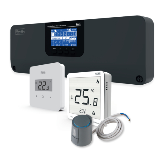
- Page 1 Roth Softline – Controller 8 ch, Master Advanced Wireless control system for underfloor heating/cooling, and radiator systems.
-
Page 2: Table Of Contents
TABLE OF CONTENT Safety ..........................3 First start-up .......................... 4 III. Main screen description ......................8 Display informations – zones Controller functions ........................ 9 1. Block Diagram – Main menu ................... 9 2. Operation global system mode ..................9 3. Zones menu........................10 3.1. -
Page 3: Safety
I. SAFETY Roth Softline Control system must always be installed by a qualified person. The controller must always be mounted on a wall or in a cabinet in a secure way. WARNING Risk of fatal electric shock from touching live connections. Before working on the controller switch off the power supply and prevent it from being accidentally switched on. -
Page 4: First Start-Up
Follow these steps when starting the device for the first time to ensure its failure-free operation: Step 1. Connect Roth Softline Controller – master, with all the devices to be controlled In order to connect the cables, remove the controller cover and connect the cables as indicated on connector labels and diagrams below: ›... - Page 5 If required up to 4 actuators can be connected to the same output/zone (32 actuators in total on the controller) Meaning: An output with 2, 3 or 4 terminals can all be connected with up to 4 actuators. Step 2. Switch on the power supply and set your language Steg 2.
- Page 6 Step 5. Configure the settings for the temperature sensors and the room regulators To enable the Roth controller - master to control a given zone, it is necessary to provide it with current temperature value. The easiest way is to use a room thermostat, where the user will be able to change the pre-set temperature value directly on the thermostat.
- Page 7 1. Display. 2. ▼ - “down” “minus” - it is used to view the menu options and decrease the value while editing parameters. During standard operation the button is used to switch between different zones parameters. 3. ▲ - “up” “plus” - it is used to view the menu options and increase the value while editing parameters. During standard operation the button is used to switch between different zones parameters.
-
Page 8: Main Screen Description
III. MAIN SCREEN DESCRIPTION 1. Day of the week 2. Current time 3. Overview of zones. If a zone is highlighted (here it’s ch 1) you can view the informations for this zone in the display. If no number is shown, no sensors are connected (here at ch 4 and ch 8). -
Page 9: Controller Functions
IV. CONTROLLER FUNCTIONS Blockdiagram – styrenhetens huvudmeny 1. MAIN MENU Blockdiagram – styrenhetens huvudmeny Block diagram – Controller main menu Menu Additonal Operation External Manual Control Time Screen Language Fitter's Service Software Zones 1 - 8 modules mode sensor mode panel settings settings... -
Page 10: Zones Menu
Holiday Normal Comfort mode mode mode mode Diagram – zonmeny 3. ZONES MENU Diagram - Zones menu Zones Sensor Operation User Floor Optimum Window Set temp. Hysteresis Calibration Actuators type mode settings heating start sensors This submenu enables the user to configure operation parameters for the particular zones. When the pre-set temperature value in a zone is reached, the controller labels the zone as sufficiently heated and the status remains unchanged until the temperature drops below the pre-set temperature by hysteresis value. -
Page 11: User Settings
Select Preview Edit Select Preview Edit 3.5 USER SETTINGS User settings Temperature Heating Floor pump settings Schedule Constant Temp. Economical Holidays settings temperature comfortable 3.5.1 Floor pump > It is possible to turn off the circulation pump, but this will result in no heating/cooling. Default ON. -
Page 12: Floor Heating
Choose “floor heating” using ▼ – pres MENU. Choose “registration” – pres MENU. Choose YES to register sensor and searching will start. Pres registration button briefly twice, on the back (see pictures below) of the floor sensor and the sensor will be found. Choose OK with MENU to leave setup. Roth Softline Standard room thermostat Roth Softline Project floor sensor 4.2 INFORMATION Here you can see the setting and status of the floor sensor. -
Page 13: Operation Mode
4.3 OPERATION MODE Operation mode for the floor sensor can be set set to either “OFF”, “Floor protection” or “Comfort”. Choose wished mode using ▼ – pres MENU. this turns off the sensor completely. Floor protection this function serves to maintain the floor temperature below the maximum temperature value in order to protect the system or flooring against overheating. -
Page 14: Optimum Start
▲ – press MENU. 8. ACTUATORS Here you have the possibility to add and control up to 6 Roth Softline wireless Radiator actuators to the zone. Registration Choose “Actuators” using ▼ – pres MENU. Choose “Registration” with ▼ or ▲ – press MENU. Confirm “YES” with MENU to start registration of actuator. - Page 15 You will now see in the display that 1/6 possible actauators is registered to the zone. Actuator removal It is possible for you to remove the actuator again using “Actuators removal”. Information Choosing “Information” gives you an overview of the specific actuators connected to the zone: Software version, opening position, wireless signal and battery level.
-
Page 16: Window Sensors
(sensor failure, communication error). 9. WINDOW SENSORS Here you have the possibility to add and control up to 6 Roth Softline Window contacts to the zone. Registration Choose “Window sensors” using ▼ – pres MENU. Choose “Registration” with ▼ or ▲ – press MENU. Confirm “YES” with MENU to start registration of Window sensor. -
Page 17: Additional Modules Menu
Diagram – meny för ytterligare moduler V. ADDITIONAL MODULES MENU Diagram – Additonal modules menu Menu Additonal modules 1 - 4 Registration Zones Signal If you need to have a larger installation of more than 8 channels, you can add up to 4 extension Controllers in this menu. Please see the manuals for the master and extention Controllers to se how to add a module. -
Page 18: External Sensor Menu
Additonal modules 1 - 4 Registration Zones Signal VI. EXTERNAL SENSOR MENU Diagram – meny för externa sensorer Diagram – External sensor menu Menu External sensor Sensor Signal Battery Temperature Registration Weathercontrol Calibration type strength level outside Wired Wireless It is possible to connect an outdoor temperature sensor which enables the user to activate the weather-based control. The system enables only one outdoor sensor to be registered on the master Controller and the current value of the outside temperature is displayed on the main screen and forwarded to other devices like the extension Controller. -
Page 19: Manual Mode Menu
Wireless Diagram – meny för manuellt läge VII. MANUAL MODE MENU Diagram – Manual mode menu Menu Manual mode Potential- Valves 1 -8 Pump free contact This function enables the user to activate particular devices (valve actuators, voltage free contact and pump) independently of the others in order to check if they operate properly. -
Page 20: Screen Settings Menu
Clock Date Automatic settings settings Diagram – tidsinställningar Diagram – meny för skärminställningar IX. SCREEN SETTINGS MENU Menu Diagram – Screen settings menu Menu Time settings Screen settings Clock Date Automatic settings settings Screen Button the Screen Display Screen Screen Damping saver sounds... -
Page 21: Fitters Menu
In order to be able to use the Roth Softline Repeater between the master – and extension controllers, it must first be configured. Please see the specific manual for the Roth Softline Project repeater. Hysteresis 3. -
Page 22: Contact Operation Mode
4. CONTACT OPERATION MODE Here you are able to change the setting for the pump and potential free contact. If you have set up a system with one or more extension control- lers you can control these outputs globally via the master controller. Potential-free- Contact Operation delay... -
Page 23: Heating - Cooling
8. HEATING – COOLING The system works in cooling mode with monitoring of the humidity in the rooms, therefore thermostats or sensors with a built-in humidity sensor must be used. If the humidity (%) in the rooms exceeds the set global maximum value, the cooling to the respective room/zone will be stopped (the valve closes). - Page 24 Setting of max. humidity When using thermostats and/or sensors with build in humidity sensors in each room, it is possible to protect the floor construction against mois- ture generation during cooling in each single room. To do this it is necessary to specify a maximum value for the humidity. This maximum value applies to the entire plant (globally). In order to set the value correctly, it is important to relate to the actual switch over room temperature and the preset minimum flow temperature (set on the heat pump or cooling device), respectively.
-
Page 25: Mixing Valve
Heating Cooling Automatic The Roth Softline Valve module must be connected to the master controller with the RS cable. Please see the specific manual for the Softline Valve module. NOTE This type of control is available only after purchasing and connecting the additional Roth Softline Valve module, which is not included in the controller delivery. -
Page 26: Software Version
Hysteresis Diagram – meny för programvaruversion XIII. SOFTWARE VERSION Diagram – Software version menu Menu Software When option is selected, the display shows the current controller software version. XIV. SCHEDULE SETTINGS The operation mode “Local/Global schedule” can be selected, previewed and edited on the Controller. Local schedule is used when separate settings are required for a single zone. - Page 27 Use button UP/DOWN and Press MENU to enter the zone to be scheduled. Use UP/DOWN and Press MENU to open “Operation mode”. Press MENU button to select “Local schdule” to edit schedule for the single zone, or select “Global schedule” to edit schedule for all zones. Use button UP/DOWN and Press MENU to “Edit”...
- Page 28 The below example describes how the schedule program is defined in time periods (1,2,3) with different set temperatures. The pre-defined schedule (Local schedule 1) will do the following: > Between 00:00 – 06:00 o’clock the temperature is set to 18 degrees. >...
-
Page 29: Software Update
“Part of the week 2” an optional schedule that makes it possible to define separate settings for specific days. For example, if the set temperature is going to be higher only in the weekends. Press MENU button to define “Part of the week 2. The procedure is the same as for setting “Part of the week 1”... -
Page 30: Alarm List
XVI. ALARM LIST System alarm Possible cause How to fix Sensor damaged (room sensor, floor sensor) Sensor shorted or damaged - Check the connection with the sensor - Replace the sensor with a new one or contact the service staff if necessary. No communication with sensor/wireless - No range Put the sensor/regulator in a different place... -
Page 31: Technical Data
XVII. TECHNICAL DATA Roth Softline Controller 8 ch, master HVAC no. 7466397028 Supply voltage 230V AC Energy consumption Number of outputs and voltage 18 (NC/NO), 230V AC Max. sustained load 18 thermal actuators (0.3 A)* (2 channels of 3 actuators and 6 of 2 actuators) - Page 32 Roth Softline Standard room thermostat HVAC no. 7466397180 Supply voltage 2 pcs. AAA 1.5V Battery life > 2 years (floor sensor > 4 years) Power consumption standby ~ 50uA Room temperature, setting range +5 - +30°C Comfort floor temperature, setting range +15 - +30°C...
Need help?
Do you have a question about the Softline – Controller 8 ch Master and is the answer not in the manual?
Questions and answers