Table of Contents
Advertisement
Quick Links
2060 Cessna Dr, Suite 100
Vacaville, CA 95688
telephone: 707-448-5151
fax: 707-448-1521
www.bloomfieldworldwide.com
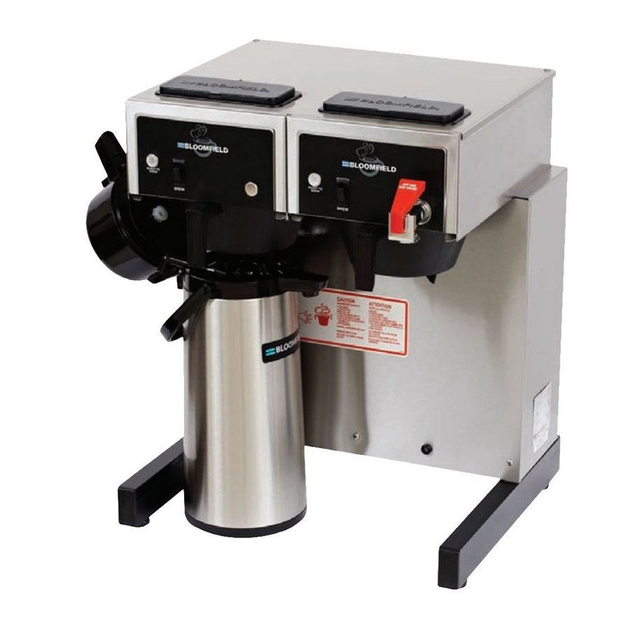
Model 8792 Brewer
with optional
7759 Airpots
p/n 2M-75873 Rev G
MODEL
8792
OWNERS MANUAL
for
DUAL COFFEE BREWER
Includes:
Installation
Operation
Use & Care
Servicing Instructions
625
21
0505
M
6
2
5
Advertisement
Table of Contents

Related Manuals for Bloomfield Gourmet 1000 8792


Summary of Contents for Bloomfield Gourmet 1000 8792
- Page 1 OWNERS MANUAL 2060 Cessna Dr, Suite 100 Vacaville, CA 95688 telephone: 707-448-5151 fax: 707-448-1521 www.bloomfieldworldwide.com DUAL COFFEE BREWER MODEL 8792 Includes: Installation Operation Use & Care Servicing Instructions Model 8792 Brewer with optional 7759 Airpots p/n 2M-75873 Rev G 0505...
- Page 2 WARRANTY STATEMENT All electrical equipment manufactured by BLOOMFIELD is warranted against defects in materials and workmanship upon the limitations in this warranty. Seller’s obligation under for a period of (1 year labor, two year parts) from the date this warranty is limited to the repair of defects without charge...
-
Page 3: Table Of Contents
TABLE OF CONTENTS WARRANTY STATEMENT Thank You for purchasing this SPECIFICATIONS FEATURES & OPERATING CONTROLS PRECAUTIONS & GENERAL INFORMATION AGENCY LISTING INFORMATION INSTALLATION INSTRUCTIONS OPERATION BREWING COFFEE CLEANING INSTRUCTIONS TROUBLESHOOTING SUGGESTIONS SERVICING INSTRUCTIONS EXPLODED VIEWS & PARTS LISTS WIRING DIAGRAMS SPECIFICATIONS Country Model... -
Page 4: Features & Operating Controls
FEATURES AND OPERATING CONTROLS POUR-OVER AIRPOT BREWER COVER POUR-OVER OPENING "READY TO BREW" LIGHT BREW SWITCH ON-OFF SWITCHES BREW CHAM BER HOT WATER FAUCET AIRPOT (BREWING POSITION) BREW NOZZLE SPRAY HEAD GASKET SPRAY DISK TIM ER ACCESS BREW HEADS (BREW CHAM BERS REM OVED) IL1712A Fig. -
Page 5: Precautions & General Information
PRECAUTIONS AND GENERAL INFORMATION WARNING: ELECTRIC SHOCK HAZARD WARNING service personnel. Do not open any access panels which require the use of tools. Failure to heed this warning can result in electrical shock. WARNING: INJURY HAZARD WARNING all applicable electrical and plumbing codes. Failure could result in property damage and personal injury. -
Page 6: Installation Instructions
INSTALLATION INSTRUCTIONS READ THIS CAREFULLY BEFORE STARTING THE INSTALLATION IMPORTANT: REFER TO EXPLODED VIEWS PAGES 18 - 21 FOR To enable the installer to make COMPONENT NAMES/NUMBERS a quality installation and to Unpack the unit. Inspect all components for completeness and minimize installation time, the condition. - Page 7 INSTALLATION INSTRUCTIONS (continued) NSF requires that the brewer be able to be moved for cleaning NOTE: This equipment must underneath. A be installed to comply with requirement. See Figure 2 below. applicable federal, state and local plumbing codes and SOLENOID ordinances.
-
Page 8: Operation
OPERATION TANK VENT TUBE BASIN HOT WATER FAUCET (RIGHT SIDE ONLY) FAUCET SHUT-OFF (RIGHT SIDE ONLY) WATER TANK TIMER BREW FAUCET WATER HEAD HEATING COIL (RIGHT SIDE ONLY) BRAIDED HOSE FAUCET SUPPLY (RIGHT SIDE ONLY) BREW CHAMBER SOLENOID W/ FAUCET BYPASS (RIGHT SIDE) SOLENOID (SINGLE - LEFT SIDE) INLET FITTING IL1718... - Page 9 OPERATION (continued) WATER HEATER HI-LIMIT THERMOSTAT Water temperature is sensed by a thermobulb inserted into the water tank. This temperature signal is fed to the thermostat, which controls line power to the THERMOBULB heating element. The setpoint temperature is adjustable at the thermostat.
-
Page 10: Brewing Coffee
BREWING COFFEE CAUTION: A. PREPARATION BURN HAZARD Exposed surfaces of the Exposed s Exposed s brewer, brew chamber Add a pre-measured amount of and airpot or server may fresh coffee grounds. be HOT to the touch, and Gently shake the brew chamber to can cause serious burns. -
Page 11: Cleaning Instructions
CLEANING INSTRUCTIONS PROCEDURE: Clean Coffee Brewer CAUTION: BURN HAZARD PRECAUTIONS: Disconnect brewer from electric power. Allow brewer to cool. Brewing and serving Brewing a Brewing a temperatures of coffee are FREQUENCY: Daily extremely hot. Hot coffee will cause TOOLS: Mild Detergent, Clean Soft Cloth or Sponge serious skin burns. -
Page 12: Troubleshooting Suggestions
TROUBLESHOOTING SUGGESTIONS SYMPTOM POSSIBLE CAUSE SUGGESTED REMEDY Check power supply cord Brewer unplugged or circuit breaker tripped Check / reset circuit breaker Thermostat set too low Set for desired temperature Allow to cool Hi-Limit thermostat tripped Reset hi-limit (8786, 8788) Water won’t heat Examine wiring &... -
Page 13: Servicing Instructions
SERVICING INSTRUCTIONS ACCESS PANELS CAUTION C C C C C C Electric Shock TOP PANEL: Hazard Remove top panel to access hot water tank, thermostat, heating Opening access panels or elements, brew circuit tubing, faucet valve and piping. removing warmer plates on this Top panel is held by two screws at the rear and a retaining lip at brew may expose uninsulated electrical components. - Page 14 SERVICING INSTRUCTIONS (continued) TEMPERATURE ADJUSTMENT CAUTION: C C C C C C SHOCK HAZARD Unplug power cord or turn circuit breaker OFF. Remove top panel. These procedures involve These pro These pro exposed electrical circuits. Pull vent tube out of tank lid and insert a thermometer of known These procedures are to accuracy in vent hole.
- Page 15 SERVICING INSTRUCTIONS (continued) TIMER ADJUSTMENT IMPORTANT: Water pressure must be between 20 p.s.i and If water pressure exceeds this Place empty decanter under brew chamber. Press BREW r. T y, a pressure the water supply line. REMOVE TANK LID ASSEMBLY OFF.
- Page 16 SERVICING INSTRUCTIONS (continued) IMPORTANT: When replacing REPLACE HEATING ELEMENT heating element, also replace Remove tank lid assembly as described on page 13. seal gaskets. Remove two hex nuts holding element to cover. Pull element from mounting holes. Reassemble in reverse order. REPLACE SOLENOID Symptom: BYPASS...
- Page 17 SERVICING INSTRUCTIONS (continued) REPLACE TIMER ASSEMBLY timer to bracket. Disconnect wiring to timer. REPLACE HOT WATER FAUCET COIL IMPORTANT: When replacing water faucet coil, also replace seal gaskets. r. Pull coil from mounting holes. REPAIR HOT WATER FAUCET NOTE: Any abrasion or seat cup will require replacing the seat cup: Work the seat cup out of the...
- Page 18 SERVICING INSTRUCTIONS (continued) PROCEDURE: Delime the Water Tank PROCEDURE: Delime the Water Tank CAUTION: CAUTION: CHEMICAL BURN HAZARD PRECAUTIONS: Disconnect brewer from electric power. Deliming chemicals may be Deliming Deliming Allow brewer to cool. caustic. Wear appropriate protective gloves and goggles FREQUENCY: As required (Brewer slow to heat) during this procedure.
- Page 19 EXPLODED VIEW & PARTS LIST HOT WATER TANK ASSEMBLY ALTERNATE IL1715 2C-70134 HOLD-DOWN STRAP BOTH SIDES 2C-73457 NUT, HEX 8-32 KEPS BOTH SIDES WS-8512-51 THERMOSTAT (BLACK BODY - INCL. SEAL & MOUNTING SCREWS) BOTH SIDES WS-86280 THERMO (ALT) (GRAY BODY - INCL. TUBE & MOUNTING SCREWS) 2I-70147 TANK COVER GASKET BOTH SIDES...
-
Page 20: Exploded Views & Parts Lists
EXPLODED VIEW & PARTS LIST (continued) CABINET PLUMBING COMPONENTS IL1720 L ” ” 4 / F ” ” 4 / L ” 2K-70130 ELBOW, SPRAYER, SILICONE 2C-72680 LOCK NUT, HEX 7-16-20 RIGHT SIDE E ” x ” x ” S ” WS-82556 FAUCET ASSEMBLY, PRESSURE RIGHT SIDE... - Page 21 EXPLODED VIEW & PARTS LIST (continued) ELECTRICAL COMPONENTS ELECTRICAL COMPONENTS ELECTRICAL COMPONENTS IL1721A ITEM PART NO. DESCRIPTION USED ON 2E-70733 SWITCH, MOMENTARY ROCKER, BREW BOTH 2J-72671 INDICATOR, 120V, READY-TO-BREW BOTH 2E-72936 SWITCH ROCKER ON-OFF BOTH 2P-70128 TIMER, 2-MINUTE (WITH DIAL & KNOB) 120V BOTH 2E-70709 TERMINAL BLOCK, 4P...
- Page 22 EXPLODED VIEW & PARTS LIST (continued) CABINET COMPONENTS ITEM PART NO. DESCRIPTION USED ON 2I-70139 GASKET, SPRAY HEAD BOTH A6-7272 SPRAY DISK, EMBOSSED BOTH A6-70163 RETAINER, SPRAY HEAD (REQUIRES DRILL/RIVETS TO INSTALL) BOTH 2P-70272 BUTTON PLUG, 1/2” DIA, PLASTIC (NON FAUCET MODELS) LEFT SIDE 2P-70053 BUTTON PLUG, 2”...
-
Page 23: Wiring Diagrams
WIRING DIAGRAM p/n 74810... - Page 24 2060 Cessna Dr, Suite 100 Vacaville, CA 95688 phone (707)448-5151 fax (707)448-1521 www.bloomfieldworldwide.com...
Need help?
Do you have a question about the Gourmet 1000 8792 and is the answer not in the manual?
Questions and answers