Advertisement
Quick Links
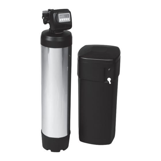
TWO TANK MODELS:
CWS100ME
CWS150ME
CWS200ME
CWS300ME
Installer, please leave with homeowner.
Homeowner, retain for future reference.
INSTR2191 0110
INSTALLATION AND OPERATING
INSTRUCTIONS
CWS SERIES RESIDENTIAL
WATER SOFTENERS
CWS100MEJ
CWS150MEJ
CWS200MEJ
CWS300MEJ
CWS100MECJ
CWS150MECJ
CWS200MECJ
CWS300MECJ
Advertisement

Related Manuals for 3M CWS Series


Summary of Contents for 3M CWS Series
- Page 1 INSTALLATION AND OPERATING INSTRUCTIONS CWS SERIES RESIDENTIAL WATER SOFTENERS TWO TANK MODELS: CWS100ME CWS100MEJ CWS100MECJ CWS150ME CWS150MEJ CWS150MECJ CWS200ME CWS200MEJ CWS200MECJ CWS300ME CWS300MEJ CWS300MECJ Installer, please leave with homeowner. Homeowner, retain for future reference. INSTR2191 0110...
- Page 3 Intended use: The CWS Series Water Softener is intended for use in softening water in homes and has not been evaluated for other uses. The system must be installed indoors near the point of entry of a home water line, and be installed by qualifi ed professional installers according to these installation instructions.
- Page 4 TABLE OF CONTENTS SECTION DESCRIPTION BEFORE INSTALLATION INSTALLATION CONTROL VALVE PROGRAMMING & REGENERATION MAINTENANCE CONTROL VALVE SERVICE INSTRUCTIONS & TROUBLESHOOTING GUIDE SYSTEM TROUBLESHOOTING GUIDE SPECIFICATIONS & OPERATING DATA PERFORMANCE DATA SHEETS PARTS LIMITED WARRANTY • Professional Installation Required: Installation requires shutting water off to home, cutting home water supply pipe and using a welding torch to add piping and fittings.
- Page 5 Check Your Pumping Rate and Water Pressure: Two water system conditions must be checked carefully to avoid unsatisfactory operation or equipment damage: 1) MINIMUM water pressure required at the water softener inlet is 20 psi (138 kPa). IF WATER PRESSURE IS OVER 80 psi (552 kPa), A PRESSURE RE- DUCING VALVE MUST BE INSTALLED IN THE WATER SUPPLY LINE AHEAD OF THE WATER SOFTENER.
- Page 6 Facts to Remember While Planning Your Installation: 1) All installation procedures MUST conform to local and state plumbing codes. 2) If lawn sprinkling, a swimming pool, or geothermal heating/cooling or water for other devices/activities are to be treated by the water softener, a larger model MUST be selected to accommodate the higher fl...
- Page 7 SECTION 2: INSTALLATION STANDARD WELL INSTALLATION FILTERED WATER FILTERED SOFT WATER PRESSURE TANK BRINE TANK WELL WATER FILTER SOFTENER (OPTIONAL) PRESSURE SWITCH PUBLIC WATER SUPPLY INSTALLATION FILTERED WATER FILTERED WATER FOR SOFT WATER LAWN SPRINKLERS OR OTHER HIGH DEMAND METER BRINE TANK WATER...
- Page 8 SECTION 2: INSTALLATION Step 1) Remove the unit from the shipping box and remove all packaging. Ensure no freight damage has occurred since shipment from our manufacturing facility. Locate the parts package and install the bypass and adapter fi ttings on the control valve to facilitate the connection to the customer’s water supply.
- Page 9 Step 7) Attach DRAIN LINE to DRAIN LINE FITTING. To prevent back pressure from reducing fl ow rate below minimum required for backwash, DRAIN LINE MUST be sized according to run length and relative height. Be careful not to bend fl exible drain tubing sharply enough to cause “kinking”...
- Page 10 SECTION 3: CONTROL VALVE PROGRAMMING AND REGENERATION Step 1 Installer Display Settings (Step 1) Press SET CLOCK. Push or to change hour (AM/PM). Press NEXT then or to change minutes. Press NEXT to lock time in. Step 2 (Step 2) Press NEXT and simultaneously for 3 seconds.
- Page 11 Diagnostics Step 1 (Step 1) Press simultaneously for 3 seconds. If screen in Step 1 does not appear in 5 seconds the lock on the valve is activated. To unlock press, , NEXT, , and SET CLOCK in sequence, then press Step 2 NEXT and simultaneously for 3 seconds.
- Page 12 Valve History Step 1 (Step 1) Press simultaneously for 3 seconds and release. Then press simultane- ously and release. If screen, to the left, does not appear is 5 seconds the lock on the valve is acti- vated. To unlock press , NEXT, and SET CLOCK in sequence, then press .
- Page 13 User Display Settings General Operation When the system is operating, one of two displays will be shown. Pressing NEXT will alternate between the displays. One of the displays is always the current time of day. The sec- ond display is one of the following: days remaining or capacity remaining.
- Page 14 SECTION 4: MAINTENANCE Replenishment of Salt Supply: The salt storage capacity of the brine tank is approximately 180 lbs. (82 kg). During each regeneration a specifi c amount of salt is consumed, thus requiring its periodic replenishment for a continuous supply of softened water (the frequency and salt dosage level is dependent on the regeneration schedule). Always replenish salt before the supply is exhausted.
- Page 15 SECTION 5: CONTROL VALVE TROUBLESHOOTING GUIDE Problem Possible Cause Solution A. AC Adapter unplugged A. Connect power B. No electric power at outlet B. Repair outlet or use working outlet 1. Timer does not display time of day C. Damaged AC Adapter C.
- Page 16 SECTION 5: CONTROL VALVE SERVICE INSTRUCTIONS Drive Assembly: Remove the valve cover to access the drive assembly. IMPORTANT NOTE: Disconnect the power source plug (black wire) from the PC board prior to disconnecting the motor or water meter plugs from the PC board. The power source plug connects to the four-pin jack.
- Page 17 Reattach the main piston to the drive cap assembly. Reattach the regenerant piston (if needed) to the main piston. Do not lubricate the piston rod, main piston or regenerant piston. Lubricant will adversely affect the clear lip seals. Reinsert the drive cap assembly and piston into the spacer stack assembly and hand tighten the drive cap assembly.
- Page 18 the left side of the control valve. Pliers may be used to unscrew the nut if necessary. With the nut removed, a slot at the top of the water meter is visible. Twist a fl at blade screwdriver in the slot between the control valve body and the meter. When the meter is part way out it is easy to remove the water meter from the housing. Once the water meter is removed from the control valve body, gently pull forward on the turbine to remove it from the shaft.
- Page 19 SECTION 6: SYSTEM TROUBLESHOOTING GUIDE Problem Cause Solution A. Electrical service to unit interrupted A. Assure permanent electrical service is working properly (check fuse, plug, pull chain, or switch) B. Timer not working. B. Replace timer assembly. 1. Hard water (unit not using salt; liquid level in C.
- Page 20 SECTION 7: SPECIFICATIONS AND OPERATING DATA ITEM CWS100ME CWS150ME CWS200ME CWS300ME CWS100MEJ CWS150MEJ CWS200MEJ CWS300MEJ CWS100MECJ CWS150MECJ CWS200MECJ CWS300MECJ Nominal Media Volume, Ft Salt Dosage, Lbs. Salt Effi cient Setting Factory Setting Maximum Setting Softening Capacity, grains At Salt Effi cient Setting 16,300 24,200 34,100...
- Page 21 SECTION 8: PERFORMANCE DATA SHEET CWS Series Performance Data Sheet Model Number CWS100ME CWS150ME CWS200ME CWS300ME CWS100MEJ CWS150MEJ CWS200MEJ CWS300MEJ CWS100MECJ CWS150MECJ CWS200MECJ CWS300MECJ Rated Service Flow (gpm) 11.0 14.3 13.5 15.2 Pressure Drop at Rated Service Flow Rate (psi) Rated Softening Capacity (Grains) 16,300 @ 4.0 lbs salt...
- Page 22 SECTION 9: PARTS COMPONENT PARTS LIST DESCRIPTION CWS100ME CWS150ME CWS200ME CWS100ME Control Valve ,with cover, less bypass, Metered Initiated (CWS) W12M170-5V3-0N W12M270-5W3-0N W12M270-5W3-0N W12M530-5G3-0N Bypass V3006 V3006 V3006 V3006 Threaded Tank Adapter FA45TX FA45TX FA45TX Tank Adapter Coupling (4” x 8 x 2.5” x 8) 2752-2 O-ring Included with Item #3 ORG-234...
- Page 23 SECTION 9: PARTS COMPONENT PARTS LIST Front Cover and Drive Assembly Drawing No. Order No. Description Quantity V1375-01 WS1 Front Cover V3107-01 WS1 Motor V3106-01 WS-1 Drive Bracket & Spring Clip V3108 WS1 PC Board V3002 WS1 Drive Assy* Not Shown V3168 WS1 AS Adapter 110V-12 V Not Shown...
- Page 24 SECTION 9: PARTS COMPONENT PARTS LIST Drive Cap Assembly, Downfl ow Piston, Regenerant Piston and Spacer Stack Assembly Drawing No. Order No. Description Quantity V3005 Spacer Stack Assembly V3004 Drive Cap Assembly V3178 Drive Back Plate V3011 Piston Down Flow Assembly V3174 Regenerant Piston V3135...
- Page 25 SECTION 9: PARTS COMPONENT PARTS LIST Injector Cap, Injector Screen, Injector, Plug and O-Ring Drawing No. Order No. Description Quantity V3176 Injector Cap V3152 O-ring 135 V3177 Injector Screen V3010-1Z Injector Assy. Z Plug V3010-1B INJECTOR ASSY B BROWN V3010-1C INJECTOR ASSY C VIOLET V3010-1E INJECTOR ASSY E WHITE...
- Page 26 SECTION 9: PARTS COMPONENT PARTS LIST Refi ll Flow Control Assembly Drawing No. Order No. Description Quantity H4615 Elbow Locking clip JCP-P-6 Polytube insert 3/8” JCPG-6PBLK Nut 3/8” H4613 Elbow Cap 3/8” V3163 O-ring 019 V3165-01* BLFC Retainer Assembly** V3182 BLFC Not Shown H4650...
- Page 27 SECTION 9: PARTS COMPONENT PARTS LIST Drain Line - 3/4” Drawing No. Order No. Description Quantity H4615 Elbow Locking Clip PKP10TS8-BULK Polytube insert 5/8 V3192 Nut 3/4 Drain Elbow V3158-01 Drain Elbow 3/4 Male V3163 O-ring 019 V3159-01 DLFC Retainer Assembly V3162-013 DLFC 1.3 gpm for 3/4 V3162-017...
- Page 28 SECTION 9: PARTS COMPONENT PARTS LIST Water Meter and Meter Plug Drawing No. Order No. Description Quantity V3151 Nut 1” QC V3003 Meter Assembly (includes drawing #3 & #4) V3118-01 Turbine V3105 O-ring 215 V3003-01 Meter Plug Assembly...
- Page 29 SECTION 9: PARTS COMPONENT PARTS LIST Order No: V3007-02 Order No: V3007-03 Description: Fitting 1” Brass Sweat Assembly Description: Fitting 3/4” Brass Sweat Assembly Drawing No. Order No. Description Quantity Drawing No. Order No. Description Quantity V3151 Nut 1” Quick Connect V3151 Nut 1”...
- Page 30 SECTION 9: PARTS COMPONENT PARTS LIST Bypass Valve Drawing No. Order No. Description Quantity V3151 Nut 1” Quick Connect V3150 Split Ring V3105 O-ring 215 V3145 Bypass 1” Rotor V3146 Bypass Cap V3147 Bypass Handle V3148 Bypass Rotor Seal Retainer V3152 O-ring 135 V3155...
- Page 31 SECTION 9: PARTS COMPONENT PARTS LIST Wrench (Order No. V3193-01) Although no tools are necessary to assembly or disassemble the valve, the wrench (shown in various positions on the valve) may be purchased to aid in assembly or disassembly. 9-10...
- Page 32 For any warranty questions, please refer to the enclosed warranty card or call 1-800-222-7880 or mail your request to: 3M Purifi cation Inc. 400 Research Parkway Meriden, CT 06450 3M is a trademark of 3M Company. 3M Purifi cation Inc. WATER QUALITY ASSOCIATION TESTED AND VALIDATED UNDER 400 Research Parkway INDUSTRY STANDARDS is a trademark of Water Quality Association.
Need help?
Do you have a question about the CWS Series and is the answer not in the manual?
Questions and answers