Advertisement
Quick Links
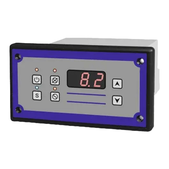
1. DESCRIPTION.
Temperature regulators of SMT series are a microprocessor-based, programmable temperature
controllers, intended for use i.a. in milk coolers and all types of dryers. The series includes following
regulators:
−
SMT-01,
−
SMT-02,
−
SMT-02H,
−
SMT-03.
Individual types differ from each other in the way of output of control inputs and outputs. The casing
of regulators in this series are adapted for panel mounting.
PPH MAKOT
ul. Przewóz 34/304
30-716 Kraków | Poland
+48 537 872 522 [Sales]
dt@makot.pl
[Support]
biuro@makot.pl
[Sales]
Page 1 of 15
Advertisement

Subscribe to Our Youtube Channel
Related Manuals for MAKOT SMT-01


Summary of Contents for MAKOT SMT-01
- Page 1 PPH MAKOT ul. Przewóz 34/304 30-716 Kraków | Poland +48 537 872 522 [Sales] dt@makot.pl [Support] biuro@makot.pl [Sales] 1. DESCRIPTION. Temperature regulators of SMT series are a microprocessor-based, programmable temperature controllers, intended for use i.a. in milk coolers and all types of dryers. The series includes following regulators: −...
-
Page 2: Technical Data
2. TECHNICAL DATA. temperature measuring range from -40 C to +120 from -40 C to +120 control temperature range (decreased by a set hysteresis) • 1 measuring resolution of the temperature C – for the range below -9,9 C and over measurer (resolution of control +100 •... - Page 3 3. CONSTRUCTION. Regulator SMT is placed in a compact casing, including all control and executive elements: The regulator is equipped with: ✓ button for switching the regulator on and off [1], ✓ button disabling automatic stirrer / ventilator operation [2], ✓...
- Page 4 ATTENTION The blue LED indicates the activation of the cooling (heating) mode. If the LED is off, and the regulator is connected to the mains, it means the cooling (heating) operation of the regulator is switched off. However, you can switch on the stirrer’s manual operation by pressing the button [3].
- Page 5 4. SCHEME OF CONNECTION OF THE REGULATOR. In order to connect the regulator to the device with which it is to be controlled, the following should be done: ✓ prepare the hole in the refrigeration device to install the regulator ✓...
-
Page 6: Regulator Functions
5. REGULATOR FUNCTIONS. The regulator is equipped with a number of functions that, together with the possibility of creating your own program, enable adjusting the regulator's work to the individual needs of the user. Some of the functions listed below are activated after the appropriate programming of the regulator (see section 6. - Page 7 10. The function of alarm signaling (visual and audible) of exceeding the set temperature range – parameters HA and HE. This function is connected with the possibility of delaying the time of switching on the alarm system of the regulator from the moment of its activation. 11.
- Page 8 6. PROGRAMMING. In order to ensure the correct working cycle of the regulator, it is necessary to program its operating parameters accordingly. By default, the controller is programmed for standard operating conditions for the purpose of controlling the milk cooler. In order to change the factory setting, enter the setting mode.
- Page 9 7. THE REGULATOR’S WORK CYCLE. When the regulator is connected to the mains and its operation is switched on with the button [1], it goes – after the delay set in parameter dE – to the control phase. The regulator controls two control circuits: control circuit for the refrigeration / heating unit;...
- Page 10 ATTENTION If the regulator is set in heating mode, the hysteresis operation has the opposite character, i.e. the heating system is switched off after the temperature has dropped below the set value, taking into account the value of the programmed hysteresis. 7.2.
-
Page 11: Additional Functions
8. ADDITIONAL FUNCTIONS. Below, some specific functions of the regulator will be described, enabling the regulator to be used for various applications. 8.1. Limit switch of the flap. The regulator is equipped with the possibility of connecting the external limit switch of the tank flap. The principle of operation of this input consists in immediately switching off the stirrer's operation at the moment of shorting or opening of this input (depending on the UU parameter setting), made by the connected limit switch of the flap. - Page 12 ATTENTION 1. In the absence of entries of maximum and minimum temperatures in the regulator's memory, the symbol --- is displayed. 2. Power supply loss causes the regulator's memory to be cleared. At any time, you can manually delete the current maximum and minimum values. The following figure illustrates manual memory erasing: 8.3.
- Page 13 ATTENTION The parameter AA is identical to the delay specified in the maximum and minimum temperature recording function. In other words, the delay value set in the parameter AA will be the same for recording maximum and minimum temperature and for parameters A1 and A2. The audible alarm can be turned off by setting the HE parameter to 1 (see section 9.).
-
Page 14: Setting Range
9. TABLE OF SEETINGS. DESCRIPTION OF THE FACTORY SYMBOL SETTING RANGE PARAMETER SETTING accessing the settings access code 0 – cooling regulator operation mode 1 – heating limitation of the lower setting the temperature from -40 C to value for the control +120 C, every 1.0 temperature range... - Page 15 0.0 – continuous work manual stirrer operation >0.0 – stirrer operation for a specified time in 5 (min.) mode the range from 1 min. to 60 min., every 1 min. delay of registering of the maximum / minimum values of temperature and setting the time from 0 h to 24 h, every 0,1 h 2 (h) delay of activation of the...
Need help?
Do you have a question about the SMT-01 and is the answer not in the manual?
Questions and answers