Advertisement
Quick Links
1. DESCRIPTION.
The second generation of MCH-07 controller is a universal, combined controller intended for use
in milking machines (devices) and milk tanks. This controller allows you to cool the milk
contained in the tank and to carry out the milk tanks and milking devices washing process.
The controller is characterized by flexibility in adapting it to various requirements. It is fully
programmable at the installation stage, and at the same time protected against possible
interference by the user in the settings.
The controller consists of two complex segments:
−
cooling segment,
−
washing segment,
however, it is not possible, even accidentally, to activate the washing process during the cooling
process. The washing segment is activated only when the cooling is switched off.
The MCH-07 controller has a waterproof casing (protection class IP65), adapted for built-up.
On request there is also a version with a flange for panel mounting (variant MCH-07.f). Power as
well as control inputs and outputs are led through glands placed on the lower part of the casing.
However, on request, a version with glands placed on the back of the casing is provided, which
allows the controller to be installed in such a way that the wires are hidden (variant MCH-07.b).
In the set with the controller there is a temperature sensor. In version MCH-07T an additional
temperature sensor is connected, which controls the heating of the water temperature during
the washing process.
The temperature sensors are in the rubber cover (protection class IP68), ending with stainless
steel sleeve. The controller signals the failure of the temperature sensor.
power supply
230V AC 50/60 HZ
protection class
safety class
IP65
CE
PPH MAKOT
ul. Przewóz 34/304
30-716 Kraków, Poland
+48 537 872 522 [Sales]
dt@makot.pl
[Support]
biuro@makot.pl
[Sales]
Strona 1 z 27
Advertisement

Related Manuals for MAKOT MCH-07 Series


Summary of Contents for MAKOT MCH-07 Series
- Page 1 PPH MAKOT ul. Przewóz 34/304 30-716 Kraków, Poland +48 537 872 522 [Sales] dt@makot.pl [Support] biuro@makot.pl [Sales] 1. DESCRIPTION. The second generation of MCH-07 controller is a universal, combined controller intended for use in milking machines (devices) and milk tanks. This controller allows you to cool the milk contained in the tank and to carry out the milk tanks and milking devices washing process.
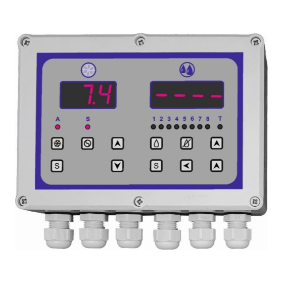
- Page 2 general view of the MCH-07 controller 2. INSTALLING AND CONNECTING THE CONTROLLER. In order to install the controller, unscrew the six screws and swivel the front of the controller, paying attention to the cable connecting the upper PCB board with the bottom board. After unfolding the casing, disconnect this cable.
- Page 3 ATTENTION Fixing the casing can be done only by screwing using the marked holes. It is forbidden to drill the casing and fix the casing through such holes, because it causes loss of tightness of the casing. MCH-07T version In the event that the relay 4 in the washing segment is set as the stirrer control, then the control of the stirrer of the cooling segment and the washing segment can be combined.
- Page 4 Control of 230V AC power via relay 5. 3. COOLING SEGMENT. Activation of the cooling process by the user blocks the possibility of switching on the washing process, which results in the total turning off of the washing segment display. view of the controller with the cooling process on Strona 4 z 27...
- Page 5 3.1. Technical data of the cooling segment. temperature measuring range from -40,0 C to +99,0 from -40,0 C to +99,0 control temperature range (decreased by a set hysteresis) measuring resolution of the temperature measurer C in the range below -9,9 (resolution of control temperature C in the range between -9,9 C and +99,0...
- Page 6 load capacity of the relay contacts 10A 250V AC controlling the stirrer 3.2. Controller functions in the cooling mode. The cooling segment of the MCH-07 controller is equipped with the functions described below. 1. Controlling the operation of the chiller (unit) according to two preset temperatures, e.g.
- Page 7 3.4. Cooling segment operation by the installer. Entering the settings can be made both when the cooling process is on or off. In the case of entering the settings when the process is on, the cooling will be interrupted and after exiting from the settings, the cooling should be switched on again.
- Page 8 limitation of the upper value for setting the temperature value from 10.0 ( the control temperature range C to +99 C, every 1,0 setting the temperature from 1,0 control hysteresis 2.0 ( to 20 C, every 0,1 blockade of control temperature 0 –...
- Page 9 Adjustments must be made so that the condition b1<b2 is always met. The values of parameters b1 and b2 are not control temperature settings; these are the temperature values between which the control temperature can be set (a section from the entire control temperature range of the controller). This function is active only when the minimum standstill time of the unit has been set (CF).
- Page 10 If this function has been activated, after pressing the button , the display will show the time to start the cooling process.In order to more accurately distinguish the displayed time, this signaling is additionally underlined by blinking alternately dots at the display. At any time, by pressing the button again you can interrupt the countdown of time, and thus go to the cooling process.
- Page 11 3.4.7. Saving the maximum and minimum temperature values during the cooling process. The controller has a function of saving in its internal memory maximum and minimum temperature values that occur throughout the controller's entire cycle. This function makes it possible to check whether the contents of the tank are stored in correct temperature conditions. At the moment the cooling is switched on, after the programmed delay has elapsed (AA –...
- Page 12 3.4.10. Returning to the factory settings. If changes are made to the factory settings and the controller is not working properly (at any stage of its use), first you need to resore the factory settings. In order to do so: → enter the settings → select PP → confirm → set parameter PP=1 → confirm →...
- Page 13 recalling from the controller memory the minimum temperature value during the cooling process recalling from the controller memory the maximum temperature value during the washing process exit the settings The following figure illustrates the procedure for handling the controller cooling segment by a direct user.
- Page 14 3.6. Description of the cooling segment operation. When the controller is connected to the power supply, the display shows the currently measured temperature. In addition to displaying the temperature value, the controller does not control any external elements. Pressing the button causes the cooling control operation to start.
- Page 15 The washing segment in the MCH-07 controller is activated only when cooling is switched off; this activation is indicated by the appearance of the - - - - symbol on the display. The washing segment may vary depending on the version of the controller: −...
- Page 16 number of programs number of factory (default) programs maximum number of steps in each program minimum duration of one step 1 s. maximum duration of one step 99 min. range of the control temperature from 9,0 C to 99,0 [only MCH-07T version] resolution of control temperature settings [only MCH-07T version] length of temperature sensor...
- Page 17 Loss of power supply interrupts the execution of the activated washing program. When the correct supply voltage returns, the program will start in the same place where it was stopped. In the settings of this function (UAP – see section 4.3.1.), it is possible to set time limit for returning to the interrupted program (in range from 1 h to 9 h).
- Page 18 4.2.11. The function of dependence on the completion of pouring water from the hydrostatic signal. The controller allows to program the end of the water dispensing proces from obtaining a signal from a hydrostatic. This function is secured by setting the maximum time for pouring water in the event of mechanical suspension of the hydrostatic.
- Page 19 2 – heating without time limit 0 – inactive; resuming setting the maximum time operation is not time-limited of power supply failure, >0 – active; setting the time after which the controller 9 (h) from 1 h to 9 h; if the break will return to the set is longer, the controller will program execution...
- Page 20 4.3.2.2. Selecting the function to be edited. In section 4.3.1. all available functions are given with their description and possible values to be set. If you want to change any from the available settings, enter the settings (see section 4.3.2.1.), and then select the specific function that will be changed. The following is a graphical representation of the change of the washing program number (program number 1 is preset).
- Page 21 The controller is equipped with: 4 washing programs (pre-programmed), which can be freely edited by the installer as required, as well as 4 washing programs to be programmed by the installer (they are empty as default). Each program can contain up to 50 steps. Each step is assigned: −...
- Page 22 4.3.3. Return to factory settings. To return to the default settings, enter the controller settings. Use the ▲ and ▼ buttons to select the Pd0d, confirm the selection by pressing the S button, then change the value of this parameter from 0 to 1 using the ▲ button. Then confirm the changes by pressing the S button again.
- Page 23 In order to set the test mode, enter the settings and change the UEL to 1, then confirm by pressing the S button. The controller test operation mode is signaled by flashing LED diode marked with the letter T. Exit from the settings by pressing the switch off button. After activating the test mode, the transition to the next steps of the program is carried out by pressing the ▲...
- Page 24 ATTENTION 1. In the b low tables, 0 means that in a given step the relay is inactive, while 1 means that the relay is active. 2. Assigning individual relays to control specific tasks is conventional. At any time, the outputs of specific relays can be used to carry out other tasks.
- Page 25 PRO3 diode no. relay no. comments step time ZW PM PPR ZZ PMY 02:00 00:30 02:00 02:30 02:30 00:30 05:00 03:00 02:00 00:30 03:30 04:00 28:00 maximum total time PRO4 diode no. relay no. comments step time CW ZW PM PPR ZZ PMY 02:30 01:00...
- Page 26 4.4.1. Starting the controller operation. The controller, after switching off the cooling section, remains in a state of readiness for operation. This is signaled by appearing - - - - symbol on the display. The washing program is activated by pressing the start button and it is signaled by the symbol From this moment, the pre-set washing program is carried out.
- Page 27 When this button is pressed, the washing program is completely interrupted and deactivated and the controller goes into the ready status. Restarting the program will cause its execution from the beginning. 4.4.4. Manual activation of the vacuum pump or the stirrer. If this function is activated (UPP parameter –...
Need help?
Do you have a question about the MCH-07 Series and is the answer not in the manual?
Questions and answers