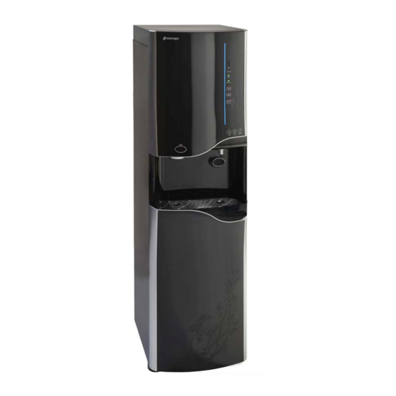
WaterLogic WL900 Installation Manual
Foot pedal
Hide thumbs
Also See for WL900:
- Service manual (29 pages) ,
- Quick start manual (9 pages) ,
- Installation manual (9 pages)
Summary of Contents for WaterLogic WL900
- Page 1 WL900 FOOT PEDAL INSTALLATION GUIDE WL900 Foot Pedal Installation Manual Page 1 - Revision: 1/5/2021...
- Page 2 3. Remove the lower front panel to access the lower compartment. To do this, remove the two screws under the lower lip of the panel, then push down and pull out. The panel should hinge outward and be free to remove and set aside. WL900 Foot Pedal Installation Manual Page 2 - Revision: 1/5/2021...
- Page 3 Be aware, the dispensing switch is mounted to the back of the dispensing button. If necessary, trace this wire up to the PCB and disconnect. WL900 Foot Pedal Installation Manual Page 3 - Revision: 1/5/2021...
- Page 4 PCB. The connection end with the two blue leads going to the pedal connector should be plugged into the PCB. This lead controls ice dispensing. WL900 Foot Pedal Installation Manual Page 4 - Revision: 1/5/2021...
- Page 5 Tie pedal leads into existing wire bundle before reinstalling panels. Replace decorative rings to both the faucet and ice dispense chute after reinstalling middle panel. WL900 Foot Pedal Installation Manual Page 5 - Revision: 1/5/2021...
- Page 6 Once the machine is connected to water and power, test the pedals for proper function, and that they are labeled correctly. **(Hot and Cold shown, but supplied labels should read “ICE” and “WATER”) WL900 Foot Pedal Installation Manual Page 6 - Revision: 1/5/2021...


Need help?
Do you have a question about the WL900 and is the answer not in the manual?
Questions and answers