Table of Contents
Advertisement
Quick Links
Advertisement
Table of Contents

Related Manuals for Marshall Amplification CV620-WH4


Summary of Contents for Marshall Amplification CV620-WH4
- Page 1 CV620-BK4/WH4 Full-HD PTZ Camera Installation Guide Ver 1.1-100517a...
-
Page 2: Table Of Contents
Table of Contents Safety Instructions .................... 4 Package Contents ..................... 6 Product Overview ....................7 Overview..................... 7 Description of LED indicator............... 7 Instruction for Installation ................8 Preparation before installation............8 Instruction for installation..............8 Connecting the device ..............17 Remote Control and Setting Menu .............. - Page 3 6.13 I would like to change the camera direction ........31 6.14 I would like to display the current status........... 31 6.15 I would like to reset to the original setting ........31 DIP Switch Setting................... 32 DIP Switch ..................32 RS-422 Connection ................
- Page 4 Page intentionally left blank...
-
Page 5: Safety Instructions
Safety Instructions Always follow these safety instructions when setting up and using the Camera: 1. Use attachments only as recommended. 2. Use the type of power source indicated on the Camera. If you are not sure of the type of power available, consult your distributor or local electricity company for advice. - Page 6 Precautions Warning: To reduce the risk of fire or electric shock, do not expose this camera to rain or moisture. If Camera will not be used for an extended time, unplug it from the power socket. Note Risk of Electric Shock Please do not open it by yourself.
-
Page 7: Package Contents
Chapter 2 Package Contents Instructions for CV620-BK4/WH4 Remote Control installation Power Cord Power Adapter RS-422 Connector Appearance may vary depending on country/region Metal Plate A Metal Plate B M3 Screws... -
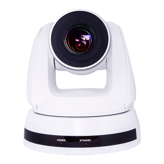
Page 8: Product Overview
Chapter 3 Product Overview 3.1 Overview Front View Rear View 1. Camera Lens 2. Power LED Indicator 3. Standby LED Indicator 4. 3G-SDI Output 5. Power Input 6. RS-422 Connection 7. RS-232 Output 8. RS-232 Input 9. DVI Output 10.OUTPUT Switch 11.IR SELECT 3.2 Description of LED indicator 3.2.1 Power... -
Page 9: Instruction For Installation
Instruction for Installation 4.1 Preparation before installation Installation and connection of the Camera requires special skills. To install by yourself, please follow necessary steps, ensure steady and tight installation of the device, and pay attention to your safety to avoid any accident. 4.1.1 Ensure the safety of the installation environment. - Page 10 Installation steps 4.2.1.2 1. Please adjust DIP switch at first prior to installation *Please refer to Chapter 7 DIP Switch Setting for the relevant descriptions on DIP switch. 2. Place the camera on a flat desk directly to ensure the normal vertical and horizontal operation of the machine 4.2.2 I would like to install CV620-BK4/WH4 on the ceiling 4.2.2.1 Prepare for the parts and equipment required during the...
- Page 11 4.2.2.3 Max. rotation dimension of camera...
- Page 12 4.2.2.4 Size Diagram 1. Metal plate A - machine side Metal plate A locking screw Metal plate A - machine side...
- Page 13 2. Metal plate B - ceiling side Metal plate B locking screw Metal plate B locking bolt M3 threaded hole M3 threaded hole M3 threaded hole Metal plate B - ceiling side...
- Page 14 3. Bottom of camera...
- Page 15 4.2.2.5 Precautions for installation 1. Before installation, please confirm the orientation of the machine relative to the object to be captured. 2. It is recommended that the machine should be set at a distance of more than 1 meter away from the object to be captured. Please adjust for a best distance according to the magnification of the lens.
- Page 16 3. Lock the metal plate B on ceiling mounted hanger Caution: (1) Please use the hanger that has obtained UL security approval (2) Please reserve the hole for the connecting wires of the camera 4. Combine the metal plate A and the metal plate B (1) Push the metal plate A up to the ceiling and then to the right to latch the metal plate B (2) And then secure with 2 M3 silver screws and 1 M3 black...
- Page 17 4.2.2.7 How to remove 1. Remove the connecting wires from the camera 2. Uninstall the camera together with the ceiling, loosen the three screws that fix the metal plates A and B and push to the left to remove the machine 3.
-
Page 18: Connecting The Device
4.3 Connecting the device 4.3.1 Image Output Connecting to a HDTV / computer monitor (DVI) 4.3.1.1 DVI cable Monitor HDTV Connecting to an HDTV (3G-SDI) 4.3.1.2 SDI Cable HDTV... - Page 19 4.3.2 Controlling CV620-BK4/WH4s with the computer Connecting to one computer for connection between 4.3.2.1 CV620-BK4/WH4s (RS-232 in/out) With RS-232 in/out, at most 7 CVs can be connected. Connecting to one computer for connection between 4.3.2.2 CV620-BK4/WH4s (RS-422) *Please refer to 7.2 RS-422 connection for the RS-422 connection instructions.
-
Page 20: Remote Control And Setting Menu
Chapter 5 Remote Control and Setting Menu 5.1 Functions of remote control * The below functions are listed alphabetically. Item Description Move the lens ,,, Back Light Turn on/off back light compensation Camera Select 1 ~ 3 CV620-BK4/WH4 select Focus- Turn on manual focus to adjust the Manual / focal length... -
Page 21: Setting Menu
5.2 Setting Menu *Press [Menu] on the remote control to enter the setting menu; the bold underlined values in the following table are defaults. 1st Level 2nd Level 3rd Level Function Descriptions Major Items Minor Items Adjustment Values 1. Full Auto 2. - Page 22 1/120 1/120 1/100 1/100 1/90 1/75 1/60 1/50 1/30 1/25 1/15 1/12 1. F1.6 2. F2 3. F2.2 4. F2.7 5. F3.2 6. F3.8 7. F4.5 8. F5.4 Iris Priority Iris priority setting 9. F6.3 10. F7.8 11. F9 12. F11 13.
- Page 23 1. 0dB 2. 2 dB 3. 4 dB 4. 6 dB 5. 8 dB 6. 10 dB 7. 12 dB 8. 14 dB Manual Gain Manually set the gain 9. 16 dB 10. 18 dB 11. 20 dB 12. 22 dB 13.
- Page 24 1/60 1/50 1/30 1/25 1/15 1/12 1. F1.6 2. F2 3. F2.2 4. F2.7 5. F3.2 6. F3.8 7. F4.5 Manual Iris 8. F5.4 Manually set the iris 9. F6.3 10. F7.8 11. F9 12. F11 13. F13 14. F16 15.
- Page 25 1. F1.6 Max. limit value of iris 2. F2.2 3. F3.2 4. F4.5 Iris Limit 5. F6.3 6. F9 7. F13 8. F18 1. Off 2. 1 3. 2 Set WDR 4. 3 5. 4 6. 5 Set the image sync 1.
- Page 26 Adjustable when the white balance mode is set to Manual Blue 0~ C~60 Manual 1. Off Picture effect Set the picture effect 2. Neg 3. B & W Adjust the sharpness of Sharpness 1~A~16 the image 1. Auto 2. Off 3.
- Page 27 Adjustable when the Gamma Image mode is set to 0~ A ~3 Custom mode Skin tone settings; adjustable when Image Skin Tone 1~ A ~5 mode is set to Custom mode Adjustable when the Brightness Image mode is set to 0~ A ~14 Custom Contrast adjustment;...
- Page 28 Set the Pan/Tilt Moving PTZ Speed On / Off speed subject to the Comp zoom position D-Zoom x1~x12 Limit the D-zoom multiple Limit 1. Off 2. Mirror Set the mode at which the Mirror D-Effect 3. Flip image is turned 4.
- Page 29 The Protocol set to PD PD Address allows the camera ID 1~ C~255 address to be assigned Camera Address 1. 1920x1080/60p 2. 1920x1080/50p 3. 1920x1080/30p 4. 1920x1080/25p 5. 1920x1080/60i 6. 1920x1080/50i 7. 1280x720/60p Choose the output Output Mode 8. 1280x720/50p resolution 9.
-
Page 30: Descriptions Of Major Functions
Chapter 6 Descriptions of Major Functions 6.1 I would like to switch to CV620-BK4/WH4 1. Press [Camera 1 ~ 3] on the remote control to select CV620-BK4/WH4. Camera 1 ~ 3 is selected with IR SELECT. 6.2 I would like to save the current lens position data 1. -
Page 31: I Would Like To Zoom In/Out Images
2. Press [ ] or [ ] to select [System]. 3. Press [ENTER] to activate. 4. Press [ ] or [ ] to select [Motionless Preset]. 5. Press [ENTER] to activate. 6. Press [ ] or [ ] to select [Off / On]. 7. -
Page 32: I Would Like To Set The Image Mode
6. Press [ ] or [ ] to select [High / Middle / Low]. 7. Press [MENU] to exit. 6.10 I would like to set the image mode 1. Press [Picture] on the remote control to switch [Off / Neg / B&W]. 6.11 I would like to freeze images 1. -
Page 33: Dip Switch Setting
Chapter 7 DIP switch setting * Please turn off the machine before changing DIP switch setting. 7.1 DIP Switch 7.1.1 OUTPUT Switch Setting Function Descriptions 1920x1080/60p 1920x1080/50p 1920x1080/30p 1920x1080/25p 1920x1080/60i 1920x1080/50i 1280x720/60p 1280x720/50p 1280x720/30p 1280x720/25p 1080/59.94p 1080/59.94i 1080/29.97p 720/59.94p 720/29.97p Reserved 7.1.2 IR SELECT Setting... -
Page 34: Rs-422 Connection
7.2 RS-422 Connection 7.2.1 RS-422 Pin Description Pin NO. Function RXD OUT - RXD OUT + TXD OUT - TXD OUT + RXD IN - RXD IN + TXD IN - TXD IN + *For SONY products, please connect IN+ to OUT+ For non-SONY products, it may be necessary to connect IN+ to OUT- 7.2.2 Use RS-422 Connection 1. - Page 35 3. Insert the wired RS-422 connector back to the camera. Now the connection is completed * When RS-422 connection is being used, do not use RS-232C connection.
-
Page 36: Troubleshooting
Chapter 8 Troubleshooting This chapter describes problems you may encounter while using the CV620-BK4/WH4. If you have questions, please refer to related chapters and follow all suggested solutions. If the problem still occurs, please contact your distributor or service center. Problems Solutions Boot without... - Page 37 screen are as far away from each other? as possible in order to avoid interference. 4. When several CV620-BK4/WH4s are connected in the same area, the operation of two remote controls at the same time may result in signal interference. It is recommended to use only one remote control.
Need help?
Do you have a question about the CV620-WH4 and is the answer not in the manual?
Questions and answers