Panasonic SF4B C Series Instruction Manual
Compact light curtain / type 4
Hide thumbs
Also See for SF4B C Series:
- Instruction manual (124 pages) ,
- Instruction manual (124 pages)

Subscribe to Our Youtube Channel
Related Manuals for Panasonic SF4B C Series


Summary of Contents for Panasonic SF4B C Series
- Page 1 Compact Light Curtain / Type 4 SF4B-□C□ Instruction Manual WUME-SF4BC-8 2017.5 panasonic.net/id/pidsx/global...
- Page 2 (MEMO) © Panasonic Industrial Devices SUNX Co., Ltd. 2017...
- Page 3 3) Though we have carefully drawn up the contents of this instruction manual, if there are any as- pects that are not clear, or any error that you may notice, please contact our local Panasonic Industrial Devices SUNX office of the nearest distributor.
-
Page 4: Table Of Contents
3-8 Functions Using Handy Controller (SFB-HC) (Optional) ······················ 80 Chapter 4 Maintenance ·····································································83 4-1 Daily Inspection ·········································································· 83 4-2 Periodic Inspection (Every Six Months) ············································ 84 4-3 Inspection after Maintenance ························································· 84 © Panasonic Industrial Devices SUNX Co., Ltd. 2017... - Page 5 MS-SF4BC-7 ································································ 106 6-3-9 Mounting with MS-SF4BCH-□ and MS-SF4BC-1 ························ 107 6-3-10 Mounting Brackets ······························································ 108 Chapter 7 Others ··········································································· 119 7-1 Glossary ················································································· 119 7-2 CE Marking Declaration of Conformity ··········································· 121 © Panasonic Industrial Devices SUNX Co., Ltd. 2017...
-
Page 6: Chapter 1 Introduction
■ Before using this device, check whether the device performs properly with the functions and capabilities as per the design specifications. ■ In case of disposal, dispose this device as an industrial waste. © Panasonic Industrial Devices SUNX Co., Ltd. 2017... - Page 7 For details, refer to “2-3-4 Device Placement.” ● Do not use this device in a reflective configuration. ● The corresponding emitter and receiver must have the same serial No. and be correctly oriented. © Panasonic Industrial Devices SUNX Co., Ltd. 2017...
- Page 8 ● Do not use this device to detect objects flying over the sensing area. ● Do not use this device to detect transparent objects, translucent objects or objects smaller than the specifi ed minimum sensing objects. © Panasonic Industrial Devices SUNX Co., Ltd. 2017...
-
Page 9: Applicable Standards / Regulations
● When this device is used in a place other than the places shown above, be sure to confirm the standards or regulations applicable in each region or country before use. © Panasonic Industrial Devices SUNX Co., Ltd. 2017... -
Page 10: Confirmation Of Packed Contents
1-4 Confirmation of Packed Contents □ Sensor: Emitter, Receiver 1 pc. each □ Test Rod 1 pc. SF4B-H□C, SF4B-H□CA-J05: SF4B-TR25 (ø25 × 220mm) □ Quick Instruction Manual (Japanese, English, Chinese, Korean) 1 pc. each language © Panasonic Industrial Devices SUNX Co., Ltd. 2017... -
Page 11: Chapter 2 Before Using This Device
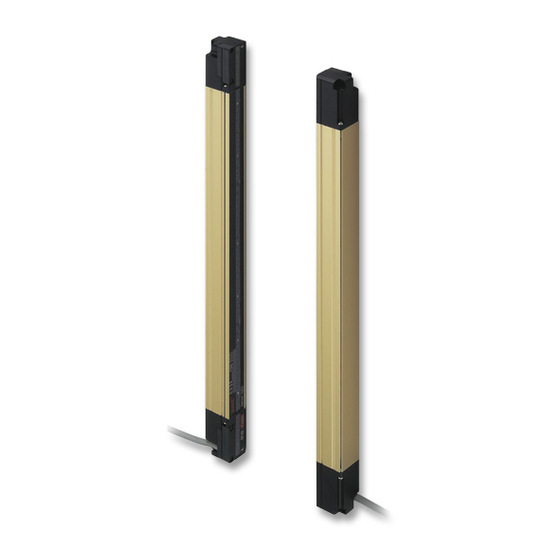
2-2 Part Description Receiver Large multi-purpose indicator Standard mounting bracket (only SF4B-□CA-J05) MS-SF4BC-1 (Optional) Beam channel Emitter Display section Large multi-purpose indicator (only SF4B-□CA-J05) Gray cable with black line Display section Gray cable © Panasonic Industrial Devices SUNX Co., Ltd. 2017... - Page 12 PNP indicator [PNP] PNP indicator [PNP] NPN indicator [NPN] NPN indicator [NPN] Emission intensity Function setting indicator control indicator [CTRL] [FUNCTION] Display section Emission halt indicator Interlock indicator [HALT] [INTERLOCK] Bottom end © Panasonic Industrial Devices SUNX Co., Ltd. 2017...
- Page 13 (OSSD 1 / 2), the operation indicator is marked as “OSSD” on the device. 3) The blanking function is set by using the handy controller (SFB-HC) (optional). Please purchase the handy controller separately. 4) The description given in [ ] is marked on the device. © Panasonic Industrial Devices SUNX Co., Ltd. 2017...
-
Page 14: Protection Area
Bottom Sensing range <Example of Correct Installation> Protective structure Sensing area Dangerous part Dangerous part Sensing area <Example of Incorrect Installation> Sensing Sensing Dangerous Dangerous area area part part © Panasonic Industrial Devices SUNX Co., Ltd. 2017... -
Page 15: Safety Distance
The safety distance is calculated based on the equation described in the next page when a per- son moves perpendicular (normal intrusion) to the sensing area of the device. Safety distance S Sensing area Dangerous part Intrusion direction © Panasonic Industrial Devices SUNX Co., Ltd. 2017... - Page 16 : Maximum halting time of machine (sec.) : Response time of this device (sec.) SF4B : Additional distance calculated from the size of the minimum sensing object of the device (mm) C = 850 (mm) © Panasonic Industrial Devices SUNX Co., Ltd. 2017...
- Page 17 Since this value matches with Case 3) above, S = 1,600 × T + 110.4 = 1,600 × 0.4 + 110.4 = 750.4 Since this value matches with Case 5) above, S is 750.4 (mm) © Panasonic Industrial Devices SUNX Co., Ltd. 2017...
- Page 18 ● Since the calculation above is performed by taking 1 (inch) = 25.4 (mm), there is a slight differ- ence between the representation in (mm) and that in (inch). Refer to the relevant standard for the details. © Panasonic Industrial Devices SUNX Co., Ltd. 2017...
-
Page 19: Influence Of Reflective Surfaces
±3° to take care of beam misalignment, etc. during installation. Allowable Distance from This Device to Reflective Surface Install in this area Do not install in this area Distance between emitter and receiver © Panasonic Industrial Devices SUNX Co., Ltd. 2017... -
Page 20: Device Placement
Receiver Receiver Emitter Receiver Emitter Emitter Emitter Barrier Receiver <Reference> The above figures are just examples of device placement. If there are any questions or problems, please contact our office. © Panasonic Industrial Devices SUNX Co., Ltd. 2017... - Page 21 Protection Area WARNING Position the emitter and receiver so that their cables are aligned. Failure to do so will cause the system to malfunction. Cable Cable Cable Cable © Panasonic Industrial Devices SUNX Co., Ltd. 2017...
-
Page 22: Mounting
● Unless otherwise specified, the following mounting procedure is common for both emitter and receiver. For the preparation of the mounting, prepare the mounting holes on the mounting sur- face by referring to “6-3 Dimensions.” © Panasonic Industrial Devices SUNX Co., Ltd. 2017... - Page 23 <In case of side mounting> Hexagon-socket head bolt [M5 (purchase separately)] Hexagon-socket head bolt [M5 (purchase separately)] Main body Main body Note: Use M5 washers (accessory of MS-SF4BC-1) when mounting to an aluminum frame. © Panasonic Industrial Devices SUNX Co., Ltd. 2017...
- Page 24 Note: SF4B-H□C□: 48 beam channels or more, SF4B-A□C□: 24 beam channels or more require intermediate supporting bracket for use with standard mounting bracket MS-SF4BC-5 (optional). SF4B-H40C□, SF4B-H48C□, SF4B-H56C□, SF4B-A20C□, SF4B-A24C□, SF4B-A28C□: 1 set SF4B-H64C□, SF4B-H72C□, SF4B-H80C□, SF4B-H88C□, SF4B-H96C□, SF4B-A32C□, SF4B-A36C□, SF4B-A40C□, SF4B-A44C□, SF4B-A48C□: 2 sets © Panasonic Industrial Devices SUNX Co., Ltd. 2017...
- Page 25 If installation space is limited, tighten the hexagon head bolts to secure the product to the mounting surface. <Space-saving installation> Hexagon head bolt Hexagon-socket head bolt [M5 (purchase separately)] Main body Main body Note: Use M5 washers (accessory of MS-SF4BC-2) when mounting to an aluminum frame. © Panasonic Industrial Devices SUNX Co., Ltd. 2017...
- Page 26 If installation space is limited, tighten the hexagon head bolts to secure the product to the mounting surface. <Space-saving installation> Hexagon head bolt Hexagon-socket head bolt [M5 (purchase separately)] Main body Main body Note: Use M5 washers (accessory of MS-SF4BC-3) when mounting to an aluminum frame. © Panasonic Industrial Devices SUNX Co., Ltd. 2017...
- Page 27 Step 2 Insert bracket A from the rear of the device. Bracket A Main body Step 3 Insert bracket B into the gap between the device and bracket A. Bracket A Bracket B Main body © Panasonic Industrial Devices SUNX Co., Ltd. 2017...
- Page 28 Note: SF4B-H□C□: 48 beam channels or more, SF4B-A□C□: 24 beam channels or more require intermediate supporting bracket for use with utility mounting bracket MS-SF4BC-4 (optional). SF4B-H40C□, SF4B-H48C□, SF4B-H56C□, SF4B-A20C□, SF4B-A24C□, SF4B-A28C□: 1 set SF4B-H64C□, SF4B-H72C□, SF4B-H80C□, SF4B-H88C□, SF4B-H96C□, SF4B-A32C□, SF4B-A36C□, SF4B-A40C□, SF4B-A44C□, SF4B-A48C□: 2 sets © Panasonic Industrial Devices SUNX Co., Ltd. 2017...
- Page 29 Notes: 1) Use M5 washers (accessory of MS-SF4BC-6) when mounting to an aluminum frame. 2) When mounting a side mounting bracket MS-SF4BC-6 (optional) to an aluminum frame, etc., pay atten- tion to the mounting direction. Projection Aluminum frame, etc. Projection Aluminum frame, etc. © Panasonic Industrial Devices SUNX Co., Ltd. 2017...
- Page 30 Aluminum frame size: □30 to 50mm Side mounting bracket MS-SF4BC-6 (Optional) Main body Aluminum frame ● When mounting to elsewhere, refer to the following figure for installation. Side mounting bracket MS-SF4BC-6 (Optional) (24mm) Main body © Panasonic Industrial Devices SUNX Co., Ltd. 2017...
- Page 31 Step 3 Insert bracket B into the gap between the device and bracket A. Bracket A Bracket B Main body Step 4 Match the hole in bracket C with the hole in bracket B. Bracket A Bracket B Bracket C Main body © Panasonic Industrial Devices SUNX Co., Ltd. 2017...
- Page 32 Note: SF4B-H□C□: 48 beam channels or more, SF4B-A□C□: 24 beam channels or more require intermediate supporting bracket for use with side mounting bracket MS-SF4BC-7 (optional). SF4B-H40C□, SF4B-H48C□, SF4B-H56C□, SF4B-A20C□, SF4B-A24C□, SF4B-A28C□: 1 set SF4B-H64C□, SF4B-H72C□, SF4B-H80C□, SF4B-H88C□, SF4B-H96C□, SF4B-A32C□, SF4B-A36C□, SF4B-A40C□, SF4B-A44C□, SF4B-A48C□: 2 sets © Panasonic Industrial Devices SUNX Co., Ltd. 2017...
- Page 33 MS-SF4BC-7 (Optional) Main body Aluminum frame ● When mounting to elsewhere, refer to the following figure for installation. Intermediate supporting bracket for use with side mounting bracket MS-SF4BC-7 (Optional) Main body (24mm) © Panasonic Industrial Devices SUNX Co., Ltd. 2017...
- Page 34 Step 2 Mount the standard mounting bracket to the machine using two hexagon-socket head bolts [M3 (length: 5 mm)]. The tightening torque should be 0.5N•m. Hexagon-socket head bolts [M3 (length: 5mm)] (Accessory of MS-SF4BC-1) Standard mounting bracket MS-SF4BC-1 (Optional) Main body © Panasonic Industrial Devices SUNX Co., Ltd. 2017...
- Page 35 Notes: 1) Use M5 washers (accessory of MS-SF4BC-1) when mounting to an aluminum frame. 2) Be careful to prevent the machine from slipping out of the protective metal case while assembling it to the mounting face. © Panasonic Industrial Devices SUNX Co., Ltd. 2017...
-
Page 36: Wiring
6) In case a surge is generated, take countermeasures such as connecting a surge ab- sorber to the origin of the surge. 7) Power supply unit corresponding to CLASS 2 (only for requiring TÜV Mark conformation). © Panasonic Industrial Devices SUNX Co., Ltd. 2017... -
Page 37: I/O Circuit Diagrams And Output Waveform
Note: Vs is the applying supply voltage. <Reference> ● K1, K2: External device (Forced guided relay or magnetic contactor) ● For more information about wiring, refer to Section 2-5-4 and subsequent sections. © Panasonic Industrial Devices SUNX Co., Ltd. 2017... - Page 38 0 to + 1.5V (source current: 5mA or less): Valid, Open: Invalid <Reference> ● K1, K2: External device (Forced guided relay or magnetic contactor) ● For more information about wiring, refer to Section 2-5-4 and subsequent sections. © Panasonic Industrial Devices SUNX Co., Ltd. 2017...
- Page 39 (Gray / Black) Large multi-purpose indicator input (Receiver side) (Black) Control output 1 (OSSD 1) (White) Control output 2 (OSSD 2) (Shield) Output polarity setting wire (Blue) 0V Internal circuit Users’ circuit © Panasonic Industrial Devices SUNX Co., Ltd. 2017...
- Page 40 Note: Vs is the applying supply voltage. <Reference> ● K1, K2: External device (Forced guided relay or magnetic contactor) ● For more information about wiring, refer to Section 2-5-4 and subsequent sections. © Panasonic Industrial Devices SUNX Co., Ltd. 2017...
- Page 41 (Gray) NC K1 K2 0.22μF (Yellow-green) External device monitor input 470Ω (Sky-blue / White) Muting input A 0.047μF 1kΩ (Sky-blue / Black) Muting input B 0.047μF 1kΩ (Blue) 0V Internal circuit Users’ circuit © Panasonic Industrial Devices SUNX Co., Ltd. 2017...
- Page 42 0 to + 1.5V (source current: 5mA or less): Lights up, Open: Turn OFF <Reference> ● K1, K2: External device (Forced guided relay or magnetic contactor) ● For more information about wiring, refer to Section 2-5-4 and subsequent sections. © Panasonic Industrial Devices SUNX Co., Ltd. 2017...
-
Page 43: Wiring · Connecting Procedure And Connector Pin Arrangement
● When the synchronization + wire (orange) and synchronization - wire (orange / black) is extend- ed with a cable other than exclusive cable, use a 0.2mm or more shielded twisted pair cable. © Panasonic Industrial Devices SUNX Co., Ltd. 2017... - Page 44 ● The connectors can be distinguished from their colors as follows: Connector for emitter: gray, connector for receiver: black ● For details of the cable with connector on one end, and the cable with connector on both ends, refer to “6-2 Options.” © Panasonic Industrial Devices SUNX Co., Ltd. 2017...
-
Page 45: Basic Wiring
(Black) Control output 1 (OSSD 1) (White) Control output 2 (OSSD 2) (Shield) Output polarity setting wire (Blue) 0V Interlock function Invalid (Auto-reset) External device monitor function Invalid Auxiliary output Cannot be used © Panasonic Industrial Devices SUNX Co., Ltd. 2017... - Page 46 (Black) Control output 1 (OSSD 1) (White) Control output 2 (OSSD 2) (Shield) Output polarity setting wire (Blue) 0V Interlock function Invalid (Auto-reset) External device monitor function Invalid Auxiliary output Cannot be used © Panasonic Industrial Devices SUNX Co., Ltd. 2017...
- Page 47 (Sky-blue / White) Muting input A (Sky-blue / Black) Muting input B (Gray / Black) Large multi-purpose indicator input (Receiver side) (Gray) NC Interlock function Invalid (Auto-reset) External device monitor function Invalid Auxiliary output Cannot be used © Panasonic Industrial Devices SUNX Co., Ltd. 2017...
- Page 48 (Sky-blue / White) Muting input A (Sky-blue / Black) Muting input B (Gray / Black) Large multi-purpose indicator input (Receiver side) (Gray) NC Interlock function Invalid (Auto-reset) External device monitor function Invalid Auxiliary output Cannot be used © Panasonic Industrial Devices SUNX Co., Ltd. 2017...
-
Page 49: Wiring For Manual Reset (Interlock Is Valid)
Vs to Vs - 2.5V (sink current 5mA or less): Emission halt (Note 1), Open: Emission K1, K2: External device (Forced guided relay or magnetic contactor) Notes: 1) Vs is the applying supply voltage. 2) For resetting, refer to “3-2 Interlock Function.” © Panasonic Industrial Devices SUNX Co., Ltd. 2017... - Page 50 Switch S1 0 to +1.5V (source current 5mA or less): Emission halt, Open: Emission K1, K2: External device (Forced guided relay or magnetic contactor) Note: For resetting, refer to “3-2 Interlock Function.” © Panasonic Industrial Devices SUNX Co., Ltd. 2017...
- Page 51 Vs to Vs - 2.5V (sink current 5mA or less): Emission halt (Note 1), Open: Emission K1, K2: External device (Forced guided relay or magnetic contactor) Notes: 1) Vs is the applying supply voltage. 2) For resetting, refer to “3-2 Interlock Function.” © Panasonic Industrial Devices SUNX Co., Ltd. 2017...
- Page 52 Switch S1 0 to +1.5V (source current 5mA or less): Emission halt, Open: Emission K1, K2: External device (Forced guided relay or magnetic contactor) Note: For resetting, refer to “3-2 Interlock Function.” © Panasonic Industrial Devices SUNX Co., Ltd. 2017...
-
Page 53: Wiring For Auto-Reset (Interlock Is Invalid)
Vs to Vs - 2.5V (sink current 5mA or less): Emission (Note), Open: Emission halt K1, K2: External device (Forced guided relay or magnetic contactor) Notes: 1) Vs is the applying supply voltage. 2) For resetting, refer to “3-2 Interlock Function.” © Panasonic Industrial Devices SUNX Co., Ltd. 2017... - Page 54 Switch S1 0 to +1.5V (source current 5mA or less): Emission, Open: Emission halt K1, K2: External device (Forced guided relay or magnetic contactor) Note: For resetting, refer to “3-2 Interlock Function.” © Panasonic Industrial Devices SUNX Co., Ltd. 2017...
- Page 55 Vs to Vs - 2.5V (sink current 5mA or less): Emission (Note), Open: Emission halt K1, K2: External device (Forced guided relay or magnetic contactor) Notes: 1) Vs is the applying supply voltage. 2) For resetting, refer to “3-2 Interlock Function.” © Panasonic Industrial Devices SUNX Co., Ltd. 2017...
- Page 56 Switch S1 0 to +1.5V (source current 5mA or less): Emission, Open: Emission halt K1, K2: External device (Forced guided relay or magnetic contactor) Note: For resetting, refer to “3-2 Interlock Function.” © Panasonic Industrial Devices SUNX Co., Ltd. 2017...
-
Page 57: Wiring Configuration For Invalid External Device Monitor Function
* Symbols Switch S1 Vs to Vs - 2.5V (sink current 5mA or less): Emission (Note), Open: Emission halt K1, K2: Safety relay unit etc. Note: Vs is the applying supply voltage. © Panasonic Industrial Devices SUNX Co., Ltd. 2017... - Page 58 The device output is selected depending on the connecting state of the output polarity setting wire (shield). Incorrect wiring may cause the lockout state. * Symbols Switch S1 0 to +1.5V (source current 5mA or less): Emission, Open: Emission halt K1, K2: Safety relay unit etc. © Panasonic Industrial Devices SUNX Co., Ltd. 2017...
- Page 59 * Symbols Switch S1 Vs to Vs - 2.5V (sink current 5mA or less): Emission (Note), Open: Emission halt K1, K2: Safety relay unit etc. Note: Vs is the applying supply voltage. © Panasonic Industrial Devices SUNX Co., Ltd. 2017...
- Page 60 The device output is selected depending on the connecting state of the output polarity setting wire (shield). Incorrect wiring may cause the lockout state. * Symbols Switch S1 0 to +1.5V (source current 5mA or less): Emission, Open: Emission halt K1, K2: Safety relay unit etc. © Panasonic Industrial Devices SUNX Co., Ltd. 2017...
-
Page 61: Wiring Configuration For Valid Muting Function (For Sf4B-□Ca-J05 Only) ·61
● Muting input A / B, Override input Vs to Vs - 2.5V (sink current 5mA or less): Valid (Note), Open: Invalid K1, K2: External device (Forced guided relay or magnetic contactor) Note: Vs is the applying supply voltage. © Panasonic Industrial Devices SUNX Co., Ltd. 2017... - Page 62 Switch S2 ● Muting input A / B, Override input 0 to + 1.5V (source current: 5mA or less): Valid, Open: Invalid K1, K2: External device (Forced guided relay or magnetic contactor) © Panasonic Industrial Devices SUNX Co., Ltd. 2017...
-
Page 63: Adjustment
Intermediate supporting bracket for use with side mounting bracket MS-SF4BC-7 (Optional) Utility mounting bracket (Optional) MS-SF4BC-2 (for rear) Hexagon socket head bolt MS-SF4BC-3 (for side) [M3 (length: 6mm)] Side mounting bracket (Optional) MS-SF4BC-6 © Panasonic Industrial Devices SUNX Co., Ltd. 2017... - Page 64 CAUTION After the beam-axis alignment is finished, make sure to confirm that all the bolts are tightened by the specified torque. For the tightening torque of each bolt, refer to “2-4 Mounting.” © Panasonic Industrial Devices SUNX Co., Ltd. 2017...
-
Page 65: Operation Test
If the indicators show reception of the light even though the test rod blocks the light, check wheth- er there is any reflective object or extraneous light source near this device or not. © Panasonic Industrial Devices SUNX Co., Ltd. 2017... -
Page 66: Operation
2) The status of the emitter / receiver indicators during operation above shows the case in PNP output set- ting mode. In case of NPN output setting mode, the NPN indicator (orange) lights up. © Panasonic Industrial Devices SUNX Co., Ltd. 2017... - Page 67 2) The status of the emitter / receiver indicators during operation above shows the case in PNP output set- ting mode. In case of NPN output setting mode, the NPN indicator (orange) lights up. © Panasonic Industrial Devices SUNX Co., Ltd. 2017...
- Page 68 2) The status of the emitter / receiver indicators during operation above shows the case in PNP output set- ting mode. In case of NPN output setting mode, the NPN indicator (orange) lights up. 3) Vs is the applying supply voltage. © Panasonic Industrial Devices SUNX Co., Ltd. 2017...
- Page 69 2) The status of the emitter / receiver indicators during operation above shows the case in PNP output set- ting mode. In case of NPN output setting mode, the NPN indicator (orange) lights up. 3) Vs is the applying supply voltage. © Panasonic Industrial Devices SUNX Co., Ltd. 2017...
- Page 70 OFF and ON again. (Source of error): The control output (OSSD) short-circuit, extraneous light detection, sensor failure, etc. Refer to “Chapter 5 Troubleshooting” and remove the source of error. © Panasonic Industrial Devices SUNX Co., Ltd. 2017...
-
Page 71: Chapter 3 Functions
The control output (OSSD 1 / 2) is turned ON automatically when this device receives the light. <Reference> It is possible to change the conditions for interlocking by using the handy controller (SFB-HC) (optional). © Panasonic Industrial Devices SUNX Co., Ltd. 2017... -
Page 72: Emission Halt Function
WARNING Do not use the emission halt function for the purpose of stopping the machine in which the SF4B-□C□ is installed. Failure to do so could result in death or serious injury. © Panasonic Industrial Devices SUNX Co., Ltd. 2017... -
Page 73: Auxiliary Output (Non-Safety Output)
[Set through the handy controller (SFB-HC) (optional)]. The auxiliary output cannot be connected to external devices. <Reference> It is also possible to set the external device monitor function into ‘invalid’ by using the handy con- troller (SFB-HC) (optional). © Panasonic Industrial Devices SUNX Co., Ltd. 2017... - Page 74 External device monitor input Lockout state <Timing chart (Error 2)> 90ms or less Light Light received received status Light blocked Control output (OSSD 1 / 2) 300ms External device monitor input Lockout state © Panasonic Industrial Devices SUNX Co., Ltd. 2017...
-
Page 75: Muting Function (For Sf4B-□Ca-J05 Only)
2) The muting indicator diagnosis function can be set with the handy controller Ver. 2 or later (SFB-HC) (optional), but it must be set to invalid. If the muting indicator diagnosis function is set to valid, the mut- ing function cannot be used. © Panasonic Industrial Devices SUNX Co., Ltd. 2017... - Page 76 Muting sensor B Muting sensor D Muting input A Muting input B <For NPN output> Muting sensor A Muting sensor C Muting sensor B Muting sensor D Muting input A Muting input B © Panasonic Industrial Devices SUNX Co., Ltd. 2017...
- Page 77 Gray cable (Orange / Black) Synchronization - (Orange / Black) Synchronization - (Orange) Synchronization + (Brown) +V Gray cable (Blue) 0V with black line (Gray / Black) Large multi-purpose indicator input (Receiver side) © Panasonic Industrial Devices SUNX Co., Ltd. 2017...
-
Page 78: Override Function (For Sf4B-□Ca-J05 Only)
If the muting indicator diagnosis function is set to valid, the muting function cannot be used. 3) The override function operates only when the auto-reset is ON (the interlock is invalid). © Panasonic Industrial Devices SUNX Co., Ltd. 2017... - Page 79 When the muting indicator diagnosis function is invalid, the muting function becomes valid 3 sec. after the input conditions of the muting sensor A (C) and B (D) were satisfied. © Panasonic Industrial Devices SUNX Co., Ltd. 2017...
-
Page 80: Functions Using Handy Controller (Sfb-Hc) (Optional)
If the auxiliary output switching function activates in No. 8 output, this device becomes OFF because the sensor itself detects the object. © Panasonic Industrial Devices SUNX Co., Ltd. 2017... - Page 81 To make the muting function valid, time difference between the time during muting input A becomes ON from OFF (Open) and the time during muting input B becomes OFF (Open) from ON should be within 3 sec. © Panasonic Industrial Devices SUNX Co., Ltd. 2017...
- Page 82 Note: Selectable with the handy controller Ver.2.1 (SFB-HC) (optional). ● Protective function Unless the password is inputted, any change in setting of the device is not allowed. The factory setting is set to be invalid for the protective function. © Panasonic Industrial Devices SUNX Co., Ltd. 2017...
-
Page 83: Chapter 4 Maintenance
In case external noise affects the operation, remove its cause and reinspect. Be sure to check the operation of the muting function before its use. Furthermore, check the state □ of the muting indicator (cleanliness or brightness, etc.) © Panasonic Industrial Devices SUNX Co., Ltd. 2017... -
Page 84: Periodic Inspection (Every Six Months)
4) When the device installation place or environment is changed. 5) When the wiring method or wiring layout is changed. 6) When FSD (Final Switching Device) parts are replaced. 7) When FSD (Final Switching Device) setting is changed. © Panasonic Industrial Devices SUNX Co., Ltd. 2017... -
Page 85: Chapter 5 Troubleshooting
0.2mm or more shielded twisted pair cable. If this device still does not work, confirm number of blinks of the error indicator and call to our local office. © Panasonic Industrial Devices SUNX Co., Ltd. 2017... - Page 86 Note: Since the color of the operation indicator changes according to ON / OFF status of the control output (OSSD 1 / 2), the operation indicator is marked as “OSSD” on the device. If the device does not work normally after checking the items above, please consult Panasonic Industrial Devices SUNX.
-
Page 87: Troubleshooting Of Receiver
(0V: PNP output, +V: NPN output). Output polarity setting wire Output polarity setting wire Wire the output polarity setting wire (shield) of the (shield) error (shield) connection of emitter receiver correctly. / receiver is incorrect. © Panasonic Industrial Devices SUNX Co., Ltd. 2017... - Page 88 Synchronization + wire (orange) or synchronization - wire Refer to “2-5 Wiring.” (orange / black) comes down or short-circuits. If the device does not work normally after checking the items above, please consult Panasonic Industrial Devices SUNX. <Reference> About counting blinks of the error indicator, count blinks from 2 seconds of no blinking.
-
Page 89: Chapter 6 Specifications / Dimensions
Blank: Unmounted, A: Mounted <Number of beam channels> <Beam pitch> H: 20mm, A: 40mm Example: SF4B-H32CA-J05 Number of beam channels: 32 channels Beam pitch: 20mm Large multi-purpose indicator: Mounted Cable specification: Relay connector type © Panasonic Industrial Devices SUNX Co., Ltd. 2017... - Page 90 Relay con- Approx. 680g Approx. 750g Approx. 840g Approx. 910g receiver) nector type PFHd: Probability of dangerous failure per hour, MTTFd: Mean time to dangerous failure. © Panasonic Industrial Devices SUNX Co., Ltd. 2017...
- Page 91 Relay con- Approx. 1,700g Approx. 1,800g Approx. 1,900g receiver) nector type PFHd: Probability of dangerous failure per hour, MTTFd: Mean time to dangerous failure. © Panasonic Industrial Devices SUNX Co., Ltd. 2017...
- Page 92 Relay con- Approx. 1,100g Approx. 1,300g Approx. 1,400g Approx. 1,600g receiver) nector type PFHd: Probability of dangerous failure per hour, MTTFd: Mean time to dangerous failure. © Panasonic Industrial Devices SUNX Co., Ltd. 2017...
- Page 93 Relay con- Approx. 1,700g Approx. 1,800g Approx. 1,900g receiver) nector type PFHd: Probability of dangerous failure per hour, MTTFd: Mean time to dangerous failure. © Panasonic Industrial Devices SUNX Co., Ltd. 2017...
- Page 94 10 to 55Hz frequency, 0.75mm amplitude in X, Y, and Z directions for two hours each Shock resistance 300m/s acceleration (Approx. 30G) in X, Y and Z directions for three times each © Panasonic Industrial Devices SUNX Co., Ltd. 2017...
- Page 95 2) When the synchronization + wire (orange) and synchronization - wire (orange / black) is extended with a cable other than exclusive cable, use a 0.2mm or more shielded twisted pair cable. © Panasonic Industrial Devices SUNX Co., Ltd. 2017...
-
Page 96: Options
For one hexagon-socket head bolt [M5]. Use one hexagon head bolt [M5] when installation space is MS-SF4BC-3 limited. <Accessory> Hexagon-socket head bolt [M3 (length: 6mm)]: 8 pcs. M5 flat washer: 4 pcs. © Panasonic Industrial Devices SUNX Co., Ltd. 2017... - Page 97 Note: The numbers of sets required by SF4B-H□C□ (40 or more beam axes) and SF4B-A□C□ (20 or more beam axes) are as follows: SF4B-H40C□, SF4B-H48C□, SF4B-H56C□, SF4B-A20C□, SF4B-A24C□, SF4B-A28C□: 1 set SF4B-H64C□, SF4B-H72C□, SF4B-H80C□, SF4B-H88C□, SF4B-H96C□, SF4B-A32C□, SF4B-A36C□, SF4B-A40C□, SF4B-A44C□, SF4B-A48C□: 2 sets © Panasonic Industrial Devices SUNX Co., Ltd. 2017...
- Page 98 Cable set SFC-WNC1 (optional) for a cable type connection is required. ● Test rod: 1 pc. Model No. Remarks Test rod for SF4B-A□C□. ø45mm SF4B-TR45 It can be also used for SF4B-H□C□ 1 beam channel floating. © Panasonic Industrial Devices SUNX Co., Ltd. 2017...
-
Page 99: Dimensions
1,463.4 1,420 1,400 SF4B-H80C(A-J05) SF4B-A40C(A-J05) 1,654.4 1,639 1,623.4 1,580 1,560 1,068 SF4B-H88C(A-J05) SF4B-A44C(A-J05) 1,814.4 1,799 1,783.4 1,740 1,720 1,175 SF4B-H96C(A-J05) SF4B-A48C(A-J05) 1,974.4 1,959 1,943.4 1,900 1,880 1,282 Type SF4B-H□C□ 21.7 SF4B-A□C□ 41.7 © Panasonic Industrial Devices SUNX Co., Ltd. 2017... -
Page 100: Side Mounting With Ms-Sf4Bc-1 And Ms-Sf4Bc-5
1,463.4 1,420 1,400 SF4B-H80C(A-J05) SF4B-A40C(A-J05) 1,654.4 1,639 1,623.4 1,580 1,560 1,063 SF4B-H88C(A-J05) SF4B-A44C(A-J05) 1,814.4 1,799 1,783.4 1,740 1,720 1,170 SF4B-H96C(A-J05) SF4B-A48C(A-J05) 1,974.4 1,959 1,943.4 1,900 1,880 1,277 Type SF4B-H□C□ 21.7 SF4B-A□C□ 41.7 © Panasonic Industrial Devices SUNX Co., Ltd. 2017... -
Page 101: Rear Mounting With Ms-Sf4Bc-2 And Ms-Sf4Bc-4
SF4B-H80C(A-J05) SF4B-A40C(A-J05) 1,639 1,580 1,560 1,676.4 1,624.4 525.5 1,072.5 SF4B-H88C(A-J05) SF4B-A44C(A-J05) 1,799 1,740 1,720 1,836.4 1,784.4 578.5 1,179.5 SF4B-H96C(A-J05) SF4B-A48C(A-J05) 1,959 1,900 1,880 1,996.4 1,944.4 631.5 1,286.5 Type SF4B-H□C□ 22.2 SF4B-A□C□ 42.2 © Panasonic Industrial Devices SUNX Co., Ltd. 2017... -
Page 102: In Case Mounting In Confined Space With Ms-Sf4Bc-2
SF4B-H80C(A-J05) SF4B-A40C(A-J05) 1,580 1,560 1,624.4 1,605.8 508.9 1,055.9 1,630.4 SF4B-H88C(A-J05) SF4B-A44C(A-J05) 1,740 1,720 1,784.4 1,765.8 561.9 1,162.9 1,790.4 SF4B-H96C(A-J05) SF4B-A48C(A-J05) 1,900 1,880 1,944.4 1,925.8 614.9 1,269.9 1,950.4 Type SF4B-H□C□ 22.2 SF4B-A□C□ 42.2 © Panasonic Industrial Devices SUNX Co., Ltd. 2017... -
Page 103: Side Mounting With Ms-Sf4Bc-3 And Ms-Sf4Bc-4
SF4B-H80C(A-J05) SF4B-A40C(A-J05) 1,639 1,580 1,560 1,676.4 1,624.4 525.5 1,072.5 SF4B-H88C(A-J05) SF4B-A44C(A-J05) 1,799 1,740 1,720 1,836.4 1,784.4 578.5 1,179.5 SF4B-H96C(A-J05) SF4B-A48C(A-J05) 1,959 1,900 1,880 1,996.4 1,944.4 631.5 1,286.5 Type SF4B-H□C□ 22.2 SF4B-A□C□ 42.2 © Panasonic Industrial Devices SUNX Co., Ltd. 2017... -
Page 104: In Case Mounting In Confined Space With Ms-Sf4Bc-3
SF4B-H80C(A-J05) SF4B-A40C(A-J05) 1,580 1,560 1,624.4 1,605.8 508.9 1,055.9 1,630.4 SF4B-H88C(A-J05) SF4B-A44C(A-J05) 1,740 1,720 1,784.4 1,765.8 561.9 1,162.9 1,790.4 SF4B-H96C(A-J05) SF4B-A48C(A-J05) 1,900 1,880 1,944.4 1,925.8 614.9 1,269.9 1,950.4 Type SF4B-H□C□ 22.2 SF4B-A□C□ 42.2 © Panasonic Industrial Devices SUNX Co., Ltd. 2017... -
Page 105: Mounting With Ms-Sf4Bc-6 And Ms-Sf4Bc-7
SF4B-H80C(A-J05) SF4B-A40C(A-J05) 1,639 1,580 1,560 1,624.4 525.5 1,072.5 1,668.4 SF4B-H88C(A-J05) SF4B-A44C(A-J05) 1,799 1,740 1,720 1,784.4 578.5 1,179.5 1,828.4 SF4B-H96C(A-J05) SF4B-A48C(A-J05) 1,959 1,900 1,880 1,944.4 631.5 1,286.5 1,988.4 Type SF4B-H□C□ 22.2 SF4B-A□C□ 42.2 © Panasonic Industrial Devices SUNX Co., Ltd. 2017... -
Page 106: In Case Mounting In Confined Space With Ms-Sf4Bc-6
SF4B-H80C(A-J05) SF4B-A40C(A-J05) 1,580 1,560 1,624.4 1,605.8 508.9 1,055.9 1,630.4 SF4B-H88C(A-J05) SF4B-A44C(A-J05) 1,740 1,720 1,784.4 1,765.8 561.9 1,162.9 1,790.4 SF4B-H96C(A-J05) SF4B-A48C(A-J05) 1,900 1,880 1,944.4 1,925.8 614.9 1,269.9 1,950.4 Type SF4B-H□C□ 22.2 SF4B-A□C□ 42.2 © Panasonic Industrial Devices SUNX Co., Ltd. 2017... -
Page 107: Mounting With Ms-Sf4Bch-□ And Ms-Sf4Bc-1
SF4B-H72C(A-J05) SF4B-A36C(A-J05) 1,494.4 1,479 1,463.4 1,420 1,400 SF4B-H80C(A-J05) SF4B-A40C(A-J05) 1,654.4 1,639 1,623.4 1,580 1,560 SF4B-H88C(A-J05) SF4B-A44C(A-J05) 1,814.4 1,799 1,783.4 1,740 1,720 SF4B-H96C(A-J05) SF4B-A48C(A-J05) 1,974.4 1,959 1,943.4 1,900 1,880 Type SF4B-H□C□ 21.7 SF4B-A□C□ 41.7 © Panasonic Industrial Devices SUNX Co., Ltd. 2017... -
Page 108: Mounting Brackets
1) Standard mounting bracket / MS-SF4BC-1 10.8 2 × M3 mounting hole (for main body mounting) 11.8 21.6 10.8 2 2 × M3 mounting hole (for main body mounting) 11.8 21.6 Material: Stainless steel © Panasonic Industrial Devices SUNX Co., Ltd. 2017... - Page 109 2) Rear utility mounting bracket / MS-SF4BC-2 (12) M3 mounting hole 7° 7° (for main body mounting) 23.8 (12) M3 mounting hole (for main body mounting) 7° 7° 23.8 Material: Stainless steel © Panasonic Industrial Devices SUNX Co., Ltd. 2017...
- Page 110 3) Side utility mounting bracket / MS-SF4BC-3 32.5 M3 mounting hole (for main body mounting) 7° 7° 22.7 32.5 M3 mounting hole (for main body mounting) 7° 7° 22.7 Material: Stainless steel © Panasonic Industrial Devices SUNX Co., Ltd. 2017...
- Page 111 Dimensions 4) Intermediate support bracket for use with utility mounting bracket / MS-SF4BC-4 <Rear mounting> 30.6 20.6 32.2 20.6 (20.2) 15.5 Material: Stainless steel © Panasonic Industrial Devices SUNX Co., Ltd. 2017...
- Page 112 Dimensions <Side mounting> 10.5 20.5 27.5 31.5 (28.5) 15.5 t1.5 Material: Stainless steel © Panasonic Industrial Devices SUNX Co., Ltd. 2017...
- Page 113 Dimensions 5) Intermediate supporting bracket for use with the standard mounting bracket / MS-SF4BC-5 <Rear mounting> 22.8 2 × M3 mounting hole 14.8 for flat head screw Material: Stainless steel © Panasonic Industrial Devices SUNX Co., Ltd. 2017...
- Page 114 Dimensions <Side mounting> 30.4 22.4 18.7 13.7 6 × M3 mounting hole 13.4 for flat head screw Material: Stainless steel © Panasonic Industrial Devices SUNX Co., Ltd. 2017...
- Page 115 Dimensions 6) Side mounting bracket / MS-SF4BC-6 22.3 (26) M3 mounting hole (for main body mounting) 7° 7° 12.5 Material: Stainless steel © Panasonic Industrial Devices SUNX Co., Ltd. 2017...
- Page 116 Dimensions 22.3 (26) M3 mounting hole (for main body mounting) 7° 7° 12.5 Material: Stainless steel © Panasonic Industrial Devices SUNX Co., Ltd. 2017...
- Page 117 Dimensions 7) Intermediate supporting bracket for use with side mounting bracket / MS-SF4BC-7 31.5 (28.5) t1.5 15.5 37.2 27.5 17.2 13.2 20.8 Material: Stainless steel © Panasonic Industrial Devices SUNX Co., Ltd. 2017...
- Page 118 984.4 860.4 MS-SF4BCH-56 1,174.4 1,159 1,144.4 1,020.4 MS-SF4BCH-64 1,334.4 1,319 1,304.4 1,180.4 MS-SF4BCH-72 1,494.4 1,479 1,464.4 1,340.4 MS-SF4BCH-80 1,654.4 1,639 1,624.4 1,500.4 MS-SF4BCH-88 1,814.4 1,799 1,784.4 1,660.4 MS-SF4BCH-96 1,974.4 1,959 1,944.4 1,820.4 © Panasonic Industrial Devices SUNX Co., Ltd. 2017...
-
Page 119: Chapter 7 Others
It is the minimum distance that must be maintained between the light curtain and the dangerous parts of a machine so that the ma- Safety distance chine can be stopped before a human body or an object can reach the dangerous parts. © Panasonic Industrial Devices SUNX Co., Ltd. 2017... - Page 120 The abbreviation for the Presence Sensing Device Initiation. The safety device that restarts automatically without any operation PSDI by the operator after the device detects danger status and halts for a while. © Panasonic Industrial Devices SUNX Co., Ltd. 2017...
-
Page 121: Ce Marking Declaration Of Conformity
CE Marking Declaration of Conformity 7-2 CE Marking Declaration of Conformity Itemized Essentials of EU Declaration of Conformity Manufacturer’s Name: Panasonic Industrial Devices SUNX Co., Ltd Manufacturer’s Address: 2431-1, Ushiyama-cho, Kasugai, Aichi 486-0901, Japan EU Representative’s Name: Panasonic Marketing Europe GmbH Panasonic Testing Center EU Representative’s Address: Winsbergring 15, 22525 Hamburg, Germany... - Page 122 : November 15, 2013 Forthd edition : May 15, 2014 Fifth edition : June 30, 2014 Sixth edition : October 20, 2015 Seventh edition : January 15, 2016 Eighth edition : May 24, 2017 © Panasonic Industrial Devices SUNX Co., Ltd. 2017...
- Page 123 (2) Any Products found to be defective must be shipped to Panasonic Industrial Devices SUNX with all shipping costs paid by Purchaser or offered to Panasonic Industrial Devices SUNX for inspection and examination.
- Page 124 ■ Overseas Sales Division (Head Office): 2431-1 Ushiyama-cho, Kasugai-shi, Aichi, 486-0901, Japan ■ Telephone: +81-568-33-7861 ■ Facsimile: +81-568-33-8591 panasonic.net/id/pidsx/global For sales network, please visit our website. © Panasonic Industrial Devices SUNX Co., Ltd. 2017 May 2017 PRINTED IN JAPAN WUME-SF4BC-8...
Need help?
Do you have a question about the SF4B C Series and is the answer not in the manual?
Questions and answers