Table of Contents

Subscribe to Our Youtube Channel
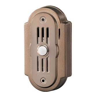
Summary of Contents for Panasonic VL-GC001A
-
Page 1: Door Station
Door Station Installation and Operation Guide VL-GC001A Model No. Thank you for purchasing a Panasonic Door Station. Please read this Installation and Operation Guide before using the unit and save for future reference. PFQX2165ZA DC0405NK0... -
Page 2: Table Of Contents
Table of Contents Important Information Important safety instructions ..........3 Additional safety information . -
Page 3: Important Information
The lightning flash with arrow head within a triangle is intended to tell the user that parts inside the product are a risk of electric shock to persons. Important safety instructions 1) Read these instructions. All the safety and operating instructions should be read before the appliance is operated. 2) Keep these instructions. -
Page 4: Additional Safety Information
Important Information Additional safety information 1. Use only the power source marked on the unit. If you are not sure of the type of power supplied to your home, consult your dealer or local power company. 2. Use only the specified AC adaptor. 3. -
Page 5: Introduction And Installation
Included items Item Door station Mounting bracket Wood screws Allen wrench Bolt covers Introduction and Installation Quantity Notes Attached to rear of the door station. For the door station. (3.8 mm x 20 mm, One for spare. ------ " x ") ------... -
Page 6: Location Of Controls
Introduction and Installation Location of controls Front view A Camera L When a visitor presses the Call Button, the camera will turn on and an image of the visitor will be shown on the display of the monitor station. B Microphone C Call Button L The Call Button is lit with a blue LED light while the power is on. -
Page 7: Before Installation
Before installation To avoid malfunction or communication disturbances, do not install the door station in the following locations: – Places where vibration or any other kind of impact occurs. – Places where echoing is frequent. – Places where a high concentration of dust, hydrogen sulfide, phosphorus, ammonia, sulfur, carbon, acid, or noxious fumes occur. - Page 8 Introduction and Installation Note: L The measurements and angles are for reference purposes and may vary depending on the environment. L If a strong light is shining on the door station, the visitor’s face may not be distinguishable. Do not place the door station in the following locations. –...
-
Page 9: Installing The Door Station
Installing the door station Make sure to install the door station on a flat, vertical wall. Important information: On the bottom surface of the door station, there is a hole to allow water to drain. Do not cover it up when installing. Unscrew the hex-head screw using the longer end of the allen wrench and remove the mounting bracket from the rear of the door station. - Page 10 Introduction and Installation Attach the mounting bracket to the wall using the wood screws (3.8 mm x 20 mm, '' x ''). L Before drilling, see page 7 for installation location. Wood screws Connect the wires that connect to the monitor station to the terminal connector by unscrewing the screws, pushing in the wires, then tightly fastening the screws.
- Page 11 Introduction and Installation L If you want to connect the wires without them going through a hole in the wall behind the mounting bracket, connect the wires by passing them through the ribs and the wire hole. Wire hole Mount the door station to the mounting bracket. Push the door station down until it is secure.
- Page 12 Introduction and Installation Insert the hex-head screw using the longer end of the allen wrench. Attach the bolt cover using the shorter end of the allen wrench. L Use protrusion on the shorter end of the allen wrench to rotate the bolt cover until it is secure.
-
Page 13: Help
Cleaning Clean the unit with a soft, dry cloth when cleaning. For excessive dirt, wipe the unit with a slightly damp cloth. Important information: L Do not use anything containing alcohol, polish powder, powder soap, benzine, thinner, wax, petroleum, or boiling water. Also do not spray with insecticide, glass cleaner, or hair spray. This could cause a change in color or quality. -
Page 14: General Information
General Information Technical data about this product Power supply Dimensions: Mass (Weight): Operating environment: Installation method: External material: *1 Supplied from the monitor station. Note: L Design and specifications are subject to change without notice. L The pictures and illustrations in these instructions may vary slightly from the actual product. -
Page 15: Fcc And Other Information
General Information FCC and Other Information This device complies with Part 15 of the FCC Rules. Operation is subject to the following two conditions: (1) This device may not cause harmful interference. (2) This device must accept any interference received, including interference that may cause undesired operation. - Page 16 San Gabriel Industrial Park, Ave. 65 de Infantería, Km. 9.5, Carolina, Puerto Rico 00985, U.S.A. Copyright: L This material is copyrighted by Panasonic Communications Co., Ltd., and may be reproduced for internal use only. All other reproduction, in whole or in part, is prohibited without the written consent of Panasonic Communications Co., Ltd.


Need help?
Do you have a question about the VL-GC001A and is the answer not in the manual?
Questions and answers