
Related Manuals for Tesla TI47UH1 MPU-24


Summary of Contents for Tesla TI47UH1 MPU-24
- Page 1 Power Anytime, Anywhere Tesla™ TI47UH1 MPU-24 User Manual Built Smart...Proven Tough Tesla Industries, Inc. 101 Centerpoint Blvd. New Castle, DE 19720 (302) 324-8910 Phone (302) 324-8912 Fax www.teslaind.com www.tesla1.com...
- Page 2 Conditioners, manufactured by Tesla™ Industries, Inc., are able to safely and effectively charge any AGM, Lead Acid battery. The Tesla™ GPU’s and chargers are voltage and current regulated to 0.01% (dual loop). The charging voltage is calibrated, by Tesla™, to 28.6 volts and is pure dc (no power line ripple).
- Page 3 Chemical Family/Classification: Tesla™ Industries, Inc. Sealed Lead Battery Synonyms: Telephone: Sealed Lead Acid Battery, VRLA Battery For information, contact Tesla™ Industries, Inc. Manufacturer's Name/Address: Customer Service Department at 302-324-8910 Tesla™ Industries, Inc 101 Centerpoint Blvd. 24-Hour Emergency Response Contact: New Castle, DE 19720-4180...
- Page 4 Supersedes: AF ECO #: 1002195 Inorganic lead and sulfuric acid electrolyte are the primary components of every battery manufactured by Tesla™ Products. There are no mercury or cadmium containing products present in batteries manufactured by Tesla™ Products. IV. FIRST AID MEASURES Inhalation: Sulfuric Acid: Remove to fresh air immediately.
-
Page 5: Table Of Contents
3.9 – Final Inspection Section 4 – Operation Procedures 4.1 – Operating Procedures 4.2 – Engine Starting Power 4.3 – General 4.4 – Operating Limits and Restrictions 4.5 – Performance 4.6 – Operating with AC Power Connected 4.7 – Temperature Specifications TI47UH1 MPU-24... - Page 6 8.4 – Specific Conditions 8.5 – General Conditions 8.6 – Temperature Conversion Chart 8.7 – Output Voltage 8.8 – Maximum Output Current Section 9 – Optional Accessories 9.1 – Tesla™ AC Line Cords Appendix 32-36 Repair Request Form TI47UH1 MPU-24...
- Page 7 Maximum MΩ megaohm Minimum Micro Power Unit NEMA National Electrical Manufacturers Association Ω power factor power factor correction root-mean-square Total Harmonic Distortion TMDE Test, Measurement, & Diagnostic Equipment Unmanned aerial vehicle Volts, Alternating Current Volts, Direct Current watts TI47UH1 MPU-24...
-
Page 8: Section 1 - Safety Review
The following symbols will appear within the warning triangles to alert the user to the specifi c type of danger or hazard. General Warning Electrical Hazard Explosion Hazard Fire Hazard Battery Warning Guard from Moisture Figure 1.2.1 – Different types of hazard and caution symbols TI47UH1 MPU-24... -
Page 9: Hazards
150°F (65°C). This protects the unit from overheating and damage. If the unit shuts down, move the unit into a cooler environment such as shade or air conditioning when possible. Perform a full function test, after the unit has been allowed to cool, prior to use. TI47UH1 MPU-24... -
Page 10: Section 2 - Product Overview
This manual contains the complete operating instructions and procedures for the TI47UH1 Micro Power Unit. The TI47UH1 MPU-24 provides dc electrical ground power for aircraft flight line and maintenance ground support operations. The unit is designed to provide 24 volt dc electrical power output for aircraft engine starting and 24 or 28.5 volts dc electrical support for ground maintenance, avionics/electrical trouble... -
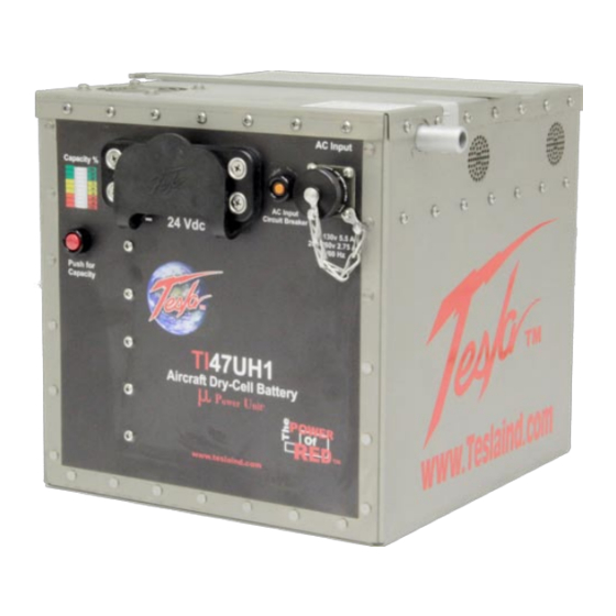
Page 11: Front Panel Overview
– Indicates the 24V battery charge state/power output status. “Press for Capacity” Button – Displays current battery charge state when pressed. AC Input Circuit Breaker – Trips if over-current fault condition occurs. AC Input Connector – Connects to Single Phase 100-260 Vac line voltage. TI47UH1 MPU-24... -
Page 12: General Specifications
-40°C to +55°C (-40°F to 131°F) with ac power Storage Temperature: • -65°C to +105°C (-85°F to 221°F) Cell Capacity: • +40°C 110% ± 05% • +25°C 100% ± 05% • +00°C ± 05% • -20°C ± 10% • -40°C ± 10% TI47UH1 MPU-24... -
Page 13: Physical Dimensions
Ensure that ports are clear at all times. When the TI47UH1 MPU-24 is plugged into 240 Vac 60 Hz AC power, the internal cooling system will efficiently regulate unit temperature regardless of load. At room temperature (+77°F) the exhaust air will not exceed the ambient temperature by more than 5°F. -
Page 14: Operating Position
The TI58D MPU-24 should be operated in the horizontal position as shown (Figure 2.7.1). Make sure that the airflow is not obstructed from outlet (Figure 2.7.2) and air intake (Figure 2.7.3). Figure 2.7.1 Airflow Figure 2.7.2 Front Outlet Figure 2.7.3 Side Inlet TI47UH1 MPU-24... -
Page 15: Section 3 - Pre-Operations
Follow the aircraft’s user manual for removal of original battery and proper disposal. Check Charge Ensure the TI47UH1-46AH MPU-24 is fully charged before installation. Place TI47UH1 MPU-24 into aircraft. Remove AC cord and place the unit in the same position as the original battery. NOTE Secure unit in aircraft. -
Page 16: Dummy Air Vents
Figure 3.2.3 Attaching DC Power Cable to Unit 3.3 –Dummy Air Vents The TI47UH1 MPU-24 has been equipped with dummy air vents to provide a receptacle for aircraft equipped with ventilation tubes (See Figure 3.3.1). Figure 3.3.1 –Dummy Air Vents... -
Page 17: Ac Input Circuit Breaker
3. Reset breaker by pressing red button. 4. Reconnect ac and dc connections to the unit. (Plug in ac line cord on military unit.) The unit should power up automatically. If the breaker continues to trip, return the unit to Tesla™ Industries for repair. -
Page 18: Charging The Unit
This is normal operation indicating the unit is in standby mode and is ready for use. Figure 3.6.1 AC Input Connector (outlined in blue) Figure 3.6.2 Attaching AC Line Cord Figure 3.6.3 Connecting unit to AC Power Supply TI47UH1 MPU-24... -
Page 19: Press For Capacity" Button And Led Status Indicator
Capacity” function. (If this sensor is tripped, allow ten minutes for unit to cool before operating “Press for Capacity” button.) Figure 3.7.1 “Press for Capacity” button location Figure 3.7.2 Pressing Button (outlined in blue) Full Charge Half Charge No Charge TI47UH1 MPU-24... -
Page 20: Battery Lock-Down
Pre-Operations 3.8 – Battery Lock-down The TI47UH1 MPU-24 is equipped with a battery lock-down (See Figure 4.8.1 below) designed to utilize the existing mounting hardware inside the battery compartment of the Huey helicopter. Figure 3.8.1 –Battery Lock-down (outlined in blue) 3.9 - Final Inspection... -
Page 21: Section 4 - Operation Procedures
1200 - 1500 peak starting amps 40-50% charged 1500 - 1800 peak starting amps 50-60% charged 1800 - 2100 peak starting amps 60-70% charged TI47UH1 MPU-24 2100 - 2400 peak starting amps 70-80% charged 2400 - 3000 peak starting amps 80-100% charged... -
Page 22: General
It is also an optimum voltage for powering avionics and lighting on most aircraft. The unit’s AC to DC converter produces continuous amps depending on the size of the system. Connect to AC Power Figure 4.6.1 Connecting unit to AC Power Supply TI47UH1 MPU-24... -
Page 23: Temperature Specifications
If the unit shuts down, move the unit into a cooler climate, such as shade or air conditioning when possible. Perform a full function test prior to use after the unit has been allowed to cool. TI47UH1 MPU-24... -
Page 24: Environmental
Fog: Check for dents, punctures, case distortion or misalignment, and cracked or loose connec tors. If no damage is evident, proceed to the next step. If damage is evident, contact Tesla™ Industries, Inc. 3.7 – Environmental Operating any electrical equipment in the presence of moisture creates possible WARNING safety hazards and/or potential for equipment damage. -
Page 25: Normal Function Test Procedures
4.9.1) capable of measuring dc and ac voltage and resistance will be required to perform some of the tests. These functional test procedures should become routine. Figure 4.9.1 – Digital Multimeter AC Neutral Pin “M” AC Hot Pin “K” AC Ground Pins “J,L” Figure 4.9.2 – AC Input Connector wiring diagram TI47UH1 MPU-24... - Page 26 When the unit is not plugged into an ac power source, the multimeter display should read 25.5 Vdc. Figure 4.9.3 – Testing DC Receptacle TI47UH1 MPU-24...
-
Page 27: Regulated 28.5 Vdc Output Ground Power
24 Vdc power output for current demands above 10 amps. Engine Starting Check dc power cable for secure and correct installation prior to engine starting. Follow ground power engine starting procedure as specified in vehicle operator’s manual. TI47UH1 MPU-24... -
Page 28: Section 5 - Post-Operation
Power Cell Recharge Limits Any time the unit’s power cells are fully discharged the unit shall be recharged within 24 hours to prevent performance degradation and ensure maximum life. Figure 5.3.1 Connecting TI47UH1 MPU-24 to AC Figure 5.3.2 AC Line Cord Power Supply... - Page 29 The TI47UH1 MPU-24’s power cells may be damaged if recharged by NiCad or Lead Acid-type battery chargers. Power cells should only be charged by either the TI47UH1 MPU-24’s internal charger and the ac power cord furnished with the equipment, or when connected to aircraft’s external dc power receptacle.
-
Page 30: Section 6 - Unit Care And Maintenance
Do not cut, crush, or drag the input or output power cables when handling the unit. Always inspect cables prior to use. If no damage is evident, proceed to the next step. If damage is evident, contact Tesla™ Customer Service. Do not attempt to use any other type of power cables other than the Tesla™ cables included with the unit. -
Page 31: Unit Servicing
Ensure proper packaging when returning the MPU. Transport the unit only in a sturdy shipping crate or Tesla™ Shipping Case. It is important to enclose the Repair Request Form. Seal the crate on all sides and return it to Tesla™ at the address listed below. Please contact Tesla™ Customer Service at (302) 324-8910 with any questions or concerns. -
Page 32: Section 7 - Troubleshooting Faq
5. Will a Tesla™ Turbo Start™ spool up a turbine engine? Nothing will start a turbine engine faster or safer than the right Tesla™ Turbo Start™. Not only will it eliminate hot starts, but it will extend the life of your starter, your engine and your battery while reducing maintenance. The Turbo Start™ senses the impedance from the starter/generator. - Page 33 Unit should never be allowed to discharge fully. In-fi eld use, it receives a dc back charge directly from a running engine. When not in use, unit should be plugged into ac power (outlet) all the time. Tesla™ systems will retain 80% of their capacity after one year of storage.
-
Page 34: Basic Usage/Operation Questions
Reset breaker by pressing red button. Reconnect ac and dc connections to the unit. (Plug in ac line cord on unit.) The unit should power up automatically. If the breaker continues to trip, return the unit to Tesla™ Industries for repair. TI47UH1 MPU-24... -
Page 35: Section 8 - Performance Data
These differences, however, are considered insignifi cant and are not individually accounted for. Ground Support and Aircraft Instrument Variations: The data shown in the performance charts do not account for instrument tolerance differences or inaccuracies. TI47UH1 MPU-24... -
Page 36: Temperature Conversion Chart
152.6 -31.0 -23.8 35.6 35.0 95.0 68.0 154.4 -30.0 -22.0 37.4 36.0 96.8 69.0 156.2 -29.0 -20.2 39.2 37.0 98.6 70.0 158.0 -28.0 -18.4 41.0 38.0 100.4 71.0 159.8 Figure 12.6.1 – Temperature conversion from Celsius to Fahrenheit. TI47UH1 MPU-24... -
Page 37: Output Voltage
Performance Data 8.7 – Output Voltage TI47UH1 MPU-24 Output Voltage 8.8 – Maximum Output Current TI47UH1 MPU-24 Maximum Output Current MAXIMUM OUTPUT CURRENT 1500 * * * * 1350 * * * * * * * 1200 (+25 C Temp) -
Page 38: Section 9 - Optional Accessories
9.1 – TESLA™ AC Line Cords AC line cords come in several lengths or can be custom-ordered to fi t your needs. Tesla™ specializes in outfi tting cables with a variety of connectors and junction boxes. Contact Tesla™ customer service to fi nd out more about our selection of cords. -
Page 39: Appendix
APPENDIX A OPTIONAL LINE CORDS FOR WORLDWIDE OPERATIONS COUNTRY VOLTS TESLA™ PART # Afghanistan TI25000-004 Old British Line Cord Algeria TI25000-004 Old British Line Cord American Samoa TI25000-011 Australian Line Cord Angola TI25000-003 Continental European Line Cord Anguilla (U.K.) TI25000-005 United Kingdom Line Cord... - Page 40 APPENDIX A (Cont.) OPTIONAL LINE CORDS FOR WORLDWIDE OPERATIONS COUNTRY VOLTS TESLA™ PART # Ecuador TI25000-001 North American Line Cord Egypt TI25000-003 Continental European Line Cord El Salvador TI25000-001 North American Line Cord England TI25000-005 United Kingdom Line Cord Equatorial Guinea...
- Page 41 APPENDIX A (Cont.) OPTIONAL LINE CORDS FOR WORLDWIDE OPERATIONS COUNTRY VOLTS TESLA™ PART # Laos TI25000-001 North American Line Cord Latvia TI25000-003 Continental European Line Cord Lebanon TI25000-003 Continental European Line Cord Lesotho TI25000-004 Old British Line Cord Liberia TI25000-005 United Kingdom Line Cord...
- Page 42 APPENDIX A (Cont.) OPTIONAL LINE CORDS FOR WORLDWIDE OPERATIONS COUNTRY VOLTS TESLA™ PART # Romania TI25000-003 Continental European Line Cord Russia TI25000-003 Continental European Line Cord Rwanda TI25000-003 Continental European Line Cord Saudi Arabia 50/60 TI25000-003 Continental European Line Cord...
- Page 43 APPENDIX A (Cont.) UNIVERSAL LINE CORD KIT FOR WORLDWIDE OPERATIONS NOTE: TESLA™ UNIVERSAL AC LINE CORD KIT, P/N: TI25000-U00, IS FOR UNITS ORIGINALLY BUILT WITH THE UNIVERSAL AC LINE CORD OPTION ONLY. THE AC ADAPTER OPTION IS TESLA™ P/N TI16000-19 AND MUST BE ORDERED WITH THE ORIGINAL PROCUREMENT OF UNIT(S).
-
Page 44: Repair Request Form
Email: _______________________________________________________________________________________ Purchase Order #: ______________________________________________________________________________ Model #: ____________________________________ Serial #: ________________________________________ Model #: ____________________________________ Serial #: ________________________________________ Shipping method to Tesla™: ______________________________________________________________________ Description of shipping package: ________________________________________________________________ Description of problem: _________________________________________________________________________ _________________________________________________________________________________________________ _________________________________________________________________________________________________ _________________________________________________________________________________________________ Return to Tesla™ 101 Centerpoint Boulevard, New Castle, DE 19720 Attention: Repair Department... - Page 45 Tesla™ 101 Centerpoint Blvd. New Castle, DE 19720 USA Tel: 302-324-8910 Fax: 302-324-8912 9475 Double R Blvd., Suite 2 Reno, NV 89521 Tel: 775-622-8801 Fax: 775-622-8810 www.teslaind.com ♦ www.tesla1.com...
Need help?
Do you have a question about the TI47UH1 MPU-24 and is the answer not in the manual?
Questions and answers