
Related Manuals for Viessmann Vitocrossal CRU 800


Summary of Contents for Viessmann Vitocrossal CRU 800
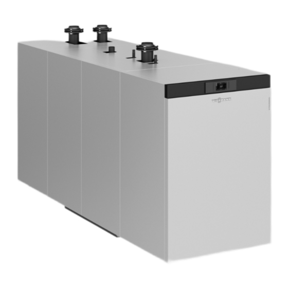
- Page 1 VIESMANN Service instructions for contractors Vitocrossal Type CRU, 800 and 1000 kW Gas condensing boiler For open flue and room sealed operation Permissible operating pressure 6 bar VITOCROSSAL Please keep safe. 5833296 GB 6/2018...
- Page 2 Danger system. Hot surfaces and fluids can lead to burns or Replace faulty components only with genuine scalding. Viessmann spare parts. Before maintenance and service work, switch ■ OFF the appliance and let it cool down. ■ Never touch hot surfaces on the boiler, burner,...
- Page 3 For replacements, use only original spare parts supplied or approved by Viessmann. Safety instructions for operating the system If you smell gas Condensate Danger...
-
Page 4: Table Of Contents
Index Index 1. Information Symbols ....................Intended use ..................Product information ................System examples ................■ 2. Commissioning, inspec- Steps - commissioning, inspection and maintenance ......tion, maintenance 3. Burner control unit Burner control unit VUC 310 ..............31 Display and programming unit ............31 ■... -
Page 5: Intended Use
Information Symbols The steps in connection with commissioning, inspec- Symbol Meaning tion and maintenance are found in the "Commission- Reference to other document containing ing, inspection and maintenance" section and identified further information as follows: Step in a diagram: Symbol Meaning The numbers correspond to the order in Steps required during commissioning... -
Page 6: Product Information
Gas condensing boiler, 800 kW and 1000 kW rated heating output with modulating MatriX-Disk burner for natural gas E and natural gas LL ■ Permissible operating pressure for the heating sys- tem: 6 bar/0.6 MPa. System examples For available system examples, see www.viessmann- schemes.com... -
Page 7: Steps - Commissioning, Inspection And Maintenance
Commissioning, inspection, maintenance Steps - commissioning, inspection and maintenance Commissioning steps Inspection steps Maintenance steps Page • 1. Filling the heating system with water and venting the system........• 2. Filling the trap with water....................• • 3. Checking the sensor well and all connections on the heating water side for tightness.......................... - Page 8 Commissioning, inspection, maintenance Steps - commissioning, inspection and… (cont.) Commissioning steps Inspection steps Maintenance steps Page • • • 39. Checking the flue system for unrestricted flow and tightness........30 • • • 40. Checking the installation room ventilation air apertures..........30 •...
-
Page 9: Filling The Heating System With Water And Venting The System
Commissioning, inspection, maintenance Filling the heating system with water and venting the system Please note Enter the amount of fill water, water hardness and pH Unsuitable water quality can damage the boiler value in the log on page 61. body. Only fill the boiler with water that complies with the "Water quality requirements": See page 59 Filling the trap with water... -
Page 10: Checking The Sensor Well And All Connections On The Heating Water Side For Tightness
Commissioning, inspection, maintenance Checking the sensor well and all connections on the heating water side for tightness Fig. 2 Female connection for control equipment: R ½ Boiler flow: PN 6, DN 100 with sensor well for boiler water temperature sensor Female connection for pressure limiter: R ½... -
Page 11: Checking The Electrical Connections
Commissioning, inspection, maintenance Checking the electrical connections Check all electrical connections for firm seating. With control cables also check: ■ Connection and kink-free routing ■ Application and seating of retaining clips Checking the gas type 1. Check with your gas supply utility regarding the 2. -
Page 12: Setting The Gas Type
Commissioning, inspection, maintenance Setting the gas type In the delivered condition, the boiler is preset for natu- ral gas E and can be changed over to natural gas LL. The setting can later be changed back to natural gas E. Fig. -
Page 13: Checking The Flue Gas Damper
Commissioning, inspection, maintenance Commissioning the system (cont.) 1. Check the heating system pressure. Permiss. operating pres- 6 bar (0.6 MPa) sure Minimum operating 0.5 bar (50 kPa) pressure Danger If the operating pressure is too low, excess temperatures in the flue system can cause leaks. -
Page 14: Reducing The Maximum Heating Output (If Required)
Commissioning, inspection, maintenance Reducing the maximum heating output (if required) The maximum heating output of the burner can be 3. S to confirm, "6" is shown under "Status" and "1" is reduced if required. shown under "Service". Programming unit on the burner control unit 4. -
Page 15: Supply Pressure
Commissioning, inspection, maintenance Checking the static pressure and supply pressure (cont.) Static pressure 1. Close the gas shut-off valve. 5. Measure the static pressure: Max. 100 mbar (10 kPa). 2. Undo the screw in test connector . Do not remove the screw. Note The max. -
Page 16: Measuring The Co 2 Content
Commissioning, inspection, maintenance Checking the static pressure and supply pressure (cont.) Supply pressure Measure (flow pressure) nat- ural gas E and LL 17 to 25 mbar Start the boiler. 1.7 to 2.5 kPa > 25 mbar Install a separate gas pressure governor with zero off upstream of the boiler system. Set >... -
Page 17: Measuring The Co Content
Commissioning, inspection, maintenance Measuring the CO content (cont.) 07. If the CO content lies outside the specified range: 08. Check the CO content at the upper and lower ■ Upper heating output: heating output again. Turn adjusting screw in very small incre- If required, set the CO content for the upper and ments until the CO... -
Page 18: Shutting Down The System
Commissioning, inspection, maintenance Checking the ionisation current (cont.) 07. Read the ionisation current. 11. S to confirm, "5" is shown under "Status". 08. Enter the actual value in the service report. repeatedly, until "0" is shown under "Service". 09. Press and hold S for longer than 2 s, flashes. -
Page 19: Opening The Boiler
Commissioning, inspection, maintenance Opening the boiler Fig. 10... -
Page 20: Opening The Combustion Chamber
Commissioning, inspection, maintenance Opening the combustion chamber 8. 3. 4. 6x Fig. 11 Danger Please note Serious injuries can result from the burner door Scratches inside the combustion chamber can falling shut. lead to corrosion damage. Secure the burner door against unintentional Never place tools or other objects inside the closure. - Page 21 Commissioning, inspection, maintenance Cleaning the combustion chamber and heating… (cont.) For stubborn residues, surface stains or soot deposits, Cleaning agent manufacturer's instructions cleaning agents can be used under the following con- ditions: ■ Only use solvent-free cleaning agents. Ensure that Recommendation: no cleaning agent gets between the boiler body and "Fauch 600"...
-
Page 22: Cleaning The Burner
Commissioning, inspection, maintenance Cleaning the burner Fig. 12 4. Press and hold the blue ring on the push-fit con- 7. Using compressed air, carefully clean the fitting nector to remove the compensation lines from the with swirl plate gas train and fan. Carefully pull off the hose. Carefully vacuum burner gauze assembly from inside. -
Page 23: Checking The Burner Gauze Assembly
Commissioning, inspection, maintenance Checking the burner door (cont.) 3. Replace any damaged seals/gaskets, packing cords and thermal insulation components. Checking the burner gauze assembly Fig. 13 1. Check burner gauze assembly and thermal 2. If a component is visibly damaged, replace the insulation block for damage. -
Page 24: Checking The Ignition Electrodes And Ionisation Electrode
Commissioning, inspection, maintenance Checking the ignition electrodes and ionisation electrode Ignition electrodes Ionisation electrode ± ± ± 21 1 Fig. 15 Fig. 14 Check the ignition electrodes and ionisation electrode for the correct gap to the burner gauze assembly and for possible damage. -
Page 25: Checking The Gas Train Valves For Tightness
Commissioning, inspection, maintenance Closing the combustion chamber (cont.) Tighten the burner door screws diagonally to a torque of 30 Nm. Danger Leaks from the burner door can result in poison- ing through escaping gas. Check the burner door for flue gas tightness, e.g. -
Page 26: Checking The Gas Train Filter Element
Commissioning, inspection, maintenance Checking the gas train valves for tightness (cont.) 6. After completing the test, close the screw on test connector . Check the test connector for leaks. Danger Escaping gas leads to a risk of explosion. Check the test connector for gas tightness. Please note The use of leak detection spray can result in faulty operation. -
Page 27: Cleaning The Condensate Drain Pipe And Trap
Commissioning, inspection, maintenance Checking the gas connections for tightness (cont.) 2. Open the gas shut-off valve. 5. Check for tightness: ■ Outlet joints of the gas train 3. Check the inlet joints of the gas train for tightness. ■ Joint between the fan and the fitting ■... -
Page 28: Checking The Condensate Drain And The Neutralising System (If Installed)
If necessary, clean the condensate drain pipe Note again. Neutralising medium from Viessmann Werke GmbH & Co. KG, part no. 9521702. 2. Check the function of the neutralising system. 4. Check entire condensate drain pipe for leaks. -
Page 29: Performing Final Checks
Commissioning, inspection, maintenance Checking the gaskets on the flue gas side (cont.) Fig. 18 1. Check the joints between flue gas collector 2. Check the flue gas temperature sensor and plug-in boiler back panel for tightness. connection for correct seating. Note 3. -
Page 30: Checking The Thermal Insulation For Firm Seating
Commissioning, inspection, maintenance Checking the thermal insulation for firm seating Checking the flue system for unrestricted flow and tightness Check the tightness of the burner door and the flue Danger gas collector a few days after commissioning. Leaking or blocked flue systems, or an inade- In the case of leaks, retighten the screws in the burner quate supply of combustion air, can cause life door with 40 Nm. -
Page 31: Burner Control Unit Vuc 310
Burner control unit Burner control unit VUC 310 Display and programming unit A display and programming unit is integrated into the Note burner control unit. Depending on the system configuration, some scans and settings can be carried out on the Vitotronic con- The following scans and settings are possible: trol unit of the boiler. -
Page 32: Selecting The Menu
Burner control unit Burner control unit VUC 310 (cont.) Start and test functions during burner start "Status" display "Service" display Meaning System start-up after power supply "ON" Standby System tests, idle state check Fan ramp-up Valve and/or relay check Pre-purge Pre-ignition Ignition, flame formation safety time Flame stabilisation... -
Page 33: Changing The Configuration
Burner control unit Burner control unit VUC 310 (cont.) Overview sub-menu to menu "1" Calling up all meter readings: — "Status" display "Service" display Start counter, 1 digit Start counter, 1000 digit Hours run meter, 1 digit Hours run meter, 1000 digit Overview sub-menu to menu "2"... - Page 34 Burner control unit Burner control unit VUC 310 (cont.) "Status" display "Service" display: Process information Unit/scale Set speed PWM variable Actual speed n in 10/min Gas pressure switch 1 0 or 1 Gas pressure switch 2 (not available for all boiler 0 or 1 types) Air pressure switch...
-
Page 35: Resetting Operating Parameters To Their Delivered Condition
Burner control unit Burner control unit VUC 310 (cont.) Example: Changing the maximum operational 4. S to confirm; "1" is shown under "Status". The burner output current value for the maximum operational out- put in % is shown under "Service". Press the following buttons: 5. -
Page 36: Flow Diagram For Burner Start
Burner control unit Flow diagram for burner start Fig. 21... -
Page 37: Description Of State
Burner control unit Flow diagram for burner start (cont.) Description of state Phase "Service" Description Duration display System start "A" System start 10 s Fan ramp-up, system start max. 20 s Forced ventilation, system start 20 s Relay test "P" Fan ramp-up for test max. -
Page 38: Troubleshooting
Troubleshooting Fault display If the burner control unit recognises a fault, the fault Fault code of the most recent fault, see table from display is automatically activated: page. ■ In the case of a non-lockout fault, the fault LED illu- minates. -
Page 39: Fault Codes With Display On Burner Control Unit
Troubleshooting Fault codes with display on burner control unit General process errors: Displayed fault codes Note Carry out measures in the order described. Each fault message is saved in the fault memory. The 10 most recent fault messages can be called up. Displayed fault System characteristics Cause... - Page 40 Troubleshooting Fault codes with display on burner control unit (cont.) Displayed fault System characteristics Cause Measures code F E5 Burner control unit in a fault Internal fault of the burner Replace burner control unit. state control unit and during test of ionisation input F EB Burner locked out...
- Page 41 Troubleshooting Fault codes with display on burner control unit (cont.) Displayed fault System characteristics Cause Measures code F F4 Poor start-up characteristics Compensation lines not Check compensation lines and (start enrichment). Solenoid connected, solenoid valve connections, replace compensa- valve not switching. faulty, output relay of tion lines.
-
Page 42: Codes
Troubleshooting Fault codes with display on burner control unit (cont.) Displayed fault System characteristics Cause Measures code F F9 No feedback from fan External fan power supply Check cable" A" and external a-Ö not connected, faulty or power supply. Replace cable or defective. -
Page 43: Faults Without Fault Display
Troubleshooting Fault codes with display on burner control unit (cont.) Detailed er- Component/signal Cause of fault Measure ror code Gas pressure High switching se- Check the gas supply. Check setting GDW1 and switch 1 quence, switch flutters gas train intake screen. External voltage Plug 41 demand T2 High switching se- Check whether external voltage present. - Page 44 Troubleshooting Faults without fault display (cont.) Fault Cause of fault Measure Flame tears off during op- Intake strainer of gas train Remove flange. Clean strainer. See page 26. eration soiled Flue gas temperature too Excessive gas throughput Adjust gas throughput in accordance with the rated high boiler heating output.
-
Page 45: Overview Of Assemblies
Parts lists Overview of assemblies The following details are required when ordering parts: ■ Serial no. (see type plate ■ Assembly (from this parts list) Position number of the individual part within the ■ assembly (from this parts list) 0004 0003 0001 0002... -
Page 46: Boiler Assembly
Parts lists Boiler assembly 0001 0001 0004 0005 0002 0007 0006 0003 0001 0005 0008 Fig. 24... - Page 47 Parts lists Boiler assembly (cont.) Pos. Part 0001 Gasket DN 100 PN 6 0002 Sensor well with clip 0003 Packing cord 0004 Gasket set 0005 Sealant 0006 Flue gas collector with gasket 0007 Flue system collar 0008 Stench trap...
-
Page 48: Casing Assembly
Parts lists Casing assembly 0029 0011 0009 0030 0031 0032 0033 0013 0014 0013 0013 0012 0008 0013 0034 0007 0010 0006 0005 0008 0021 0020 0007 0035 0006 0022 0005 0003 0004 0036 0017 0037 0019 0015 0025 0024 0028 0026 0001... - Page 49 0030 Top panel, left 0031 Top panel, right 0032 Top panel, centre 0033 Top panel, back 0034 Back panel, top 0035 Control unit cover 0036 Back panel, centre 0037 Back panel, bottom 0038 Viessmann logo 0039 Vitocrossal logo 0040 Fixings...
-
Page 50: Matrix-Disk Burner Assembly
Parts lists MatriX-Disk burner assembly 0020 0021 0017 0006 0013 0002 0007 0014 0011 0016 0018 0008 0016 0022 0015 0004 0012 0019 0023 0005 0008 0010 0015 0010 0003 0009 0001 0023 Fig. 26... - Page 51 Parts lists MatriX-Disk burner assembly (cont.) Pos. Part 0001 Matrix-Disk burner 0002 Burner control unit and cables 0003 0004 Gas train 0005 Mixer unit 0006 Gas pressure switch 0007 Gas pressure switch 0008 Supply air collector 0009 Gasket, gas fan 0010 O-ring gasket 0011...
-
Page 52: Burner Control Unit Assembly
Parts lists Burner control unit assembly 0001 0002 0003 0004 0005 0006 0009 0010 0011 0012 0013 0018 0014 0015 0016 0017 0019 Fig. 27... - Page 53 Parts lists Burner control unit assembly (cont.) Pos. Part 0001 Burner control unit VUC310-C01.005 0002 Programming unit 0003 Connecting cable, 38 bypass 0004 Ionisation cable 11/auxiliary earth 0005 Ignition transformer connecting cable 54 0006 Gas train connecting cable 0009 Air pressure switch with connecting cable 131 0010 Air pressure switch with connecting cable 131A 0011...
-
Page 54: Vitotronic Control Unit Assembly
Parts lists Vitotronic control unit assembly 0003 0001 0002 0003 0008 0004 0003 0002 0006 0007 0013 0010 0011 0017 0009 0016 0014 0019 0012 0018 Fig. 28... - Page 55 Parts lists Vitotronic control unit assembly (cont.) Pos. Part 0001 Programming module 0002 Toggle switch OFF 2-pole 0003 Slider, left and right 0004 Vitotronic programming unit 0006 Cable with 2 angle connectors 0007 LAN cable 0008 Vitocrossal junction box 0009 Coding card 0010 Cover, cable entry (2 pce)
-
Page 56: Overview Of Burner Components
Component overview Overview of burner components Fig. 29 Display and programming unit Supply air collector Burner control unit Thermal insulation block Burner door Ignition electrodes Gas train Burner gauze assembly, MatriX-Disk Gas pressure switch 1 Ionisation electrode Gas pressure switch 2 Ignition unit Gas supply pipe Air pressure switch LDW2... -
Page 57: Function Description
Function description Air pressure switch Fan pressure monitoring function (LDW1) The switching threshold of air pressure switch 1 (plug The fault shutdown is indicated by fault codes "F F5" and "F F7" on the burner control unit display (see ) is monitored in all fan ramp-up phases and checked during modulating burner operation. -
Page 58: Burner Control Unit Connection Diagram
Connection diagrams Burner control unit connection diagram Fig. 31 Junction box Fuel valve BV2 Mains connection to main MCB/fuse 400 V/50 Hz, Display and programming unit see the following chapter Gas pressure switch GDW2 Burner control unit VUC 310 Air pressure switch 1 Flame monitor (ionisation current) Gas pressure switch GDW1 Vitotronic control unit... -
Page 59: Water Quality Requirements
Water quality requirements Water quality requirements Note Prevention of damage due to scaling Observing the following requirements is necessary to safeguard your warranty rights. Prevent excessive scale build-up (calcium carbonate) The warranty excludes damage due to corrosion and on the heating surfaces. For heating systems with scaling. - Page 60 Water quality requirements (cont.) Failure to observe the requirements of VDI Guideline Correctly sized sealed unvented systems operating at 2035 can result in damaging limescale deposits. In the correct pressure, e.g. systems with expansion ves- such cases, the service life of the installed boilers will, sel, offer good protection against the ingress of air- most often, already have been reduced.
- Page 61 Reports Reports Fill water report Fill water Top-up water Meter reading Total water volume Date — — — — — — — — — — — — — — — — — — — Max. fill volume: ......m...
- Page 62 Reports Reports (cont.) Water quality report Total hardness pH value Water treatment Date Feedwater Boiler water Boiler water Medium Dosing volume The pH value should be between 8.2 and 9.5. Settings and measurement values Commissioning Maintenance/Service Static pressure mbar Supply pressure (flow pressure) Natural gas E mbar Natural gas LL...
- Page 63 Reports Reports (cont.) Commissioning Maintenance/Service Flue gas temperature Actual °C (gross) °C Ionisation current At the upper rated heat- μ ■ ing output At the lower rated heat- ■ μ ing output Draught Actual...
- Page 64 Specification Specification Boiler Vitocrossal, type CRU 800 CRU 1000 Rated heating output range 80/60 °C 125 to 750 156 to 938 50/30 °C 137 to 800 171 to 1000 cond Rated heating input range Qn (Sized for up to mean 127 to 762 159 to 952 sea level (MSL) 1500 m)
- Page 65 Specification Specification (cont.) Vitocrossal, type CRU 800 CRU 1000 Rated heating output range 80/60 °C 125 to 750 156 to 938 50/30 °C 137 to 800 171 to 1000 cond Gas flow rate, natural gas LL (G25) at 15 °C, 1.013 bar At rated heating output 93.8...
- Page 66 Specification Specification (cont.) MatriX-Disk burner Vitocrossal, type CRU 800 CRU 1000 Rated heating output range 80/60 °C 125 to 750 156 to 938 50/30 °C 137 to 800 171 to 1000 cond Rated heating input range Qn (Sized for up to mean 127 to 762 159 to 952 sea level (MSL) 1500 m)
-
Page 67: Final Decommissioning And Disposal
Final decommissioning Final decommissioning and disposal Viessmann products can be recycled. Components For decommissioning the system, isolate the system and substances from the system are not part of ordi- from the power supply and allow components to cool nary household waste. -
Page 68: Declaration Of Conformity
Manufacturer's certificate according to the 1st BImSchV [Germany] We, Viessmann Werke GmbH & Co. KG, D-35107 Allendorf, confirm that the product Vitocrossal, type CRU complies with the following conditions stipulated by the 1st German Immissions Order (BImSchV): limits in accordance with paragraph 6 (1). -
Page 69: Keyword Index
Keyword index Keyword index Combustion operation, service display...... 35 Air pressure switch.............57 Component overview, burner........56 Assembly Condensate drain, checking........28 – Boiler............... 46 Condensate drain pipe, cleaning........27 – Burner control unit...........52 Configuration, changing..........33 – Casing..............48 Connection diagram........... 58 –... - Page 70 Keyword index Keyword index (cont.) Manual operation............35 Safety valves, checking..........29 Measuring Spare parts..............45 – CO2 content............16 Specification...............64 – CO content.............. 17 Start and test functions during burner start..31, 36 – Flue gas temperature..........17 Static pressure, checking........... 14 Menu overview............
- Page 72 Viessmann Werke GmbH & Co. KG Viessmann Limited D-35107 Allendorf Hortonwood 30, Telford Telephone: +49 6452 70-0 Shropshire, TF1 7YP, GB Fax: +49 6452 70-2780 Telephone: +44 1952 675000 www.viessmann.com Fax: +44 1952 675040 E-mail: info-uk@viessmann.com...
Need help?
Do you have a question about the Vitocrossal CRU 800 and is the answer not in the manual?
Questions and answers