Advertisement
Installation Instructions
Assembly of Boiler Sections,
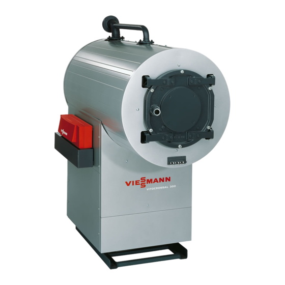
for Vertomat VSB-17 to -89
and Vitocrossal 300, CT3-17 to -89 boilers
Safety and Installation Requirements
Please ensure that these instructions are read and understood before commencing installation. Failure to comply with the
instructions listed below can cause product/property damage, severe personal injury, and/or loss of life.
Working on the equipment
The installation, adjustment, service,
and maintenance of this product must
be done by a licensed professional
heating contractor who is qualified and
experienced in the installation, service,
and maintenance of hot water boilers.
There are no user serviceable parts on
the boiler, burner, or control.
Assembly Instructions
Fig. 1
Assembly of combustion chamber
5285 410 v1.1 11/2007
Ensure main power supply to
equipment, the heating system, and all
external controls has been deactivated.
Close main gas supply valve. Take
precautions in all instances to avoid
accidental activation of power during
service work.
Part No. 7134 271
Ensure that the installation
literature of other components
is referenced.
IMPORTANT
Never put any tools, bolts or any other
parts inside the combustion chamber.
1. Clean combustion chamber surfaces
with stainless steel wire brush
5"/127 mm from the edges.
IMPORTANT
Do not use solvents. Use only clean
towels and/or rags.
2. Apply supplied tape
of the front cone section as
illustrated, and finish with 3"/76 mm
loop tabs.
3. Apply supplied tape
from edge of main boiler section as
illustrated, and finish with 3"/76 mm
loop tabs.
4. Apply generous amount of supplied
Dirko silicone evenly between the
combustion chamber edge and the
steel ring welded to the front
section
.
Do not discard empty tubes! Empty
tubes are used for removal of excess
silicone. See next step.
on the edge
3
/
"/10 mm
8
Advertisement
Table of Contents


Need help?
Do you have a question about the Vertomat VSB-17 and is the answer not in the manual?
Questions and answers