Table of Contents
Advertisement
Reference Manual
VectorStar
mmWave Modules
MA25400A Broadband mmWave Module
MA25300A Broadband mmWave Module
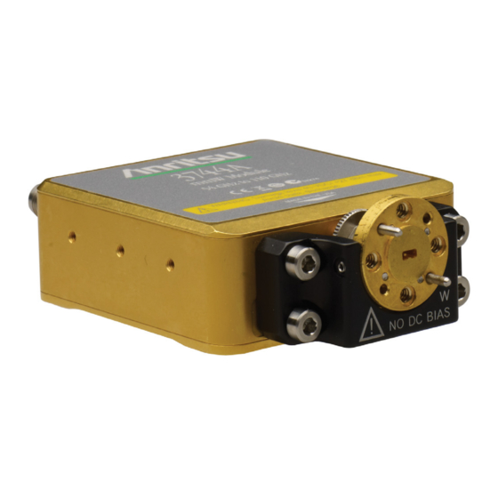
3743A/AX Broadband mmWave Module
3743E/EX Broadband mmWave Module
3744A-EE Banded mmWave Module
3744E-EE Banded mmWave Module
3744A-EW Banded mmWave Module
3744E-EW Banded mmWave Module
3744A-Rx Receiver mmWave Module
3744E-Rx Receiver mmWave Module
EE and EW Waveguide Adapter Kits
MA25300A
3744A-Rx
3744E-Rx
Anritsu Company
490 Jarvis Drive
Morgan Hill, CA 95037-2809
USA
http://www.anritsu.com
™
Broadband/Banded
3743A/AX
3743A/AX
3743E/EX
3743E/EX
3744A-EE
3744A-EE
EE
3744A-E
3744A-EW
EW
MA25400A
Part Number: 10410-00311
Copyright 2021 Anritsu Company, USA. All Rights Reserved.
3
3744E-EE
3
3744E-EW
3744E-EW
Revision: H
Published: August 2021
Advertisement
Table of Contents

Related Manuals for Anritsu VectorStar 3743A/AX


Summary of Contents for Anritsu VectorStar 3743A/AX
- Page 1 3743A/AX 3743E/EX 3743E/EX MA25300A 3744E-EE 3744A-EE 3744A-EE 3744E-EW 3744E-EW 3744A-EW 3744A-E 3744A-Rx 3744E-Rx MA25400A Anritsu Company Part Number: 10410-00311 490 Jarvis Drive Revision: H Morgan Hill, CA 95037-2809 Published: August 2021 Copyright 2021 Anritsu Company, USA. All Rights Reserved. http://www.anritsu.com...
- Page 2 Front-2 PN: 10410-00311 Rev. H VectorStar ME7838 Modules RM...
-
Page 3: Table Of Contents
Table of Contents Chapter 1 — General Information Introduction ..............1-1 Broadband/Banded mmWave Modules . - Page 4 Table of Contents (Continued) Adapter Installation ............7-3 Two-Port Alignment .
-
Page 5: Chapter 1 - General Information
Chapter 1 — General Information 1-1 Introduction ™ This chapter provides information about the VectorStar Broadband/Banded mmWave Modules. These modules are used with the ME7838 Series VectorStar Broadband/Banded mmWave VNA Systems. 1-2 Broadband/Banded mmWave Modules Table 1-1. mmWave Module Models Model Description Frequency Band... -
Page 6: Related Documentation
1-3 Related Documentation General Information 1-3 Related Documentation The following document lists are applicable to the modules covered in this reference manual. • VectorStar™ Vector Network Analyzers and Accessories Product Information, Compliance, and Safety – 10100-00063 ME7838A/AX Documents The following documentation is available for the VectorStar ME7838A Broadband/mmWave VNA System: •... -
Page 7: Vectorstar™ Me7838X4 Series Multiport Bb/Mmwave Vna Measurement System
The Acrobat Reader program is required to view the manual, and is available free from Adobe at: http://www.adobe.com. Except for the maintenance manual, all documents are available for free on the Anritsu Internet site. Printed copies of manuals and the maintenance guide are available for sale at nominal prices. Updates to this manual, if any, may also be downloaded from the Anritsu Internet site at: http://www.anritsu.com... - Page 8 1-3 Related Documentation General Information PN: 10410-00311 Rev. H VectorStar ME7838 Modules RM...
-
Page 9: Chapter 2 - Ma25400A Mmwave Module
Chapter 2 — MA25400A mmWave Module 2-1 Introduction This chapter provides a description of the MA25400A millimeter-Wave (mmWave or as labeled, mm-W) Module. The MA25400A Module is used with the VectorStar ME7838 Series Broadband/mmWave (BB/mmWave) VNA System. When the ME7838 system is ordered, the typical configuration provides a 3739C Broadband Test Set and two mmWave modules to be used with the VNA. -
Page 10: As-Shipped Configuration
2-2 MA25400A mmWave Module and Bracket MA25400A mmWave Module Certain mating devices (like the 33GG50 thru and on-wafer probes) have center pins that can move laterally if bumped. Be sure the pins are roughly centered (using the magnifying loupe in the accessory kit or a microscope) before mating. - Page 11 TEST SSMC Connector • To tighten, use a 4 mm (5/32 in) torque end wrench set to less than 0.17 Nꞏm (1.5 lbfꞏin). • Recommended is Anritsu 01-529-R torque wrench. LO K Connector • To tighten, use an 8 mm (5/16”) torque end wrench set to 0.9 Nꞏm (8 lbfꞏin).
-
Page 12: Alternate Configuration
• Recommended is Anritsu 01-201. REF SSMC Connector • To tighten, use a 4 mm (5/32 in) torque end wrench set to less than 0.17 Nꞏm (1.5 lbfꞏin). • Recommended is Anritsu 01-529-R torque wrench. Factory Calibrated Port Assignment Label Module Serial Number Label Figure 2-3. -
Page 13: Use Suggestions
MA25400A mmWave Module 2-2 MA25400A mmWave Module and Bracket Use Suggestions • The flange interface is based on a standard UG-387 waveguide flange and one connects to it by first lining up the alignment pins and then mating the flanges. •... - Page 14 2-2 MA25400A mmWave Module and Bracket MA25400A mmWave Module PN: 10410-00311 Rev. H VectorStar ME7838 Modules RM...
-
Page 15: Chapter 3 - Ma25300A Mmwave Module
Chapter 3 — MA25300A mmWave Module 3-1 Introduction This chapter provides a description of the MA25300A millimeter-Wave (mmWave or as labeled, mm-W) Module. The MA25300A Module is used with the VectorStar ME7838 Series Broadband/BB/mmWave VNA System. When the ME7838 system is ordered, the typical configuration provides a 3739C Broadband Test Set and two mmWave modules to be used with the VNA. - Page 16 • To tighten, use a torque end wrench and a plain end wrench. • 0.8 – 6 mm Torque End Wrench set to 0.45 Nꞏm (4 lbfꞏin). Recommended is Anritsu 01-524. • 0.8 – 6 mm / 7 mm Open End Wrench. Recommended is Anritsu 01-525.
-
Page 17: Alternate Configuration
• Recommended is Anritsu 01-201. REF SSMC Connector • To tighten, use a 4 mm (5/32 in) torque end wrench set to less than 0.17 Nꞏm (1.5 lbfꞏin). • Recommended is Anritsu 01-529-R torque wrench. Factory Calibrated Port Assignment Label Module Serial Number Label Figure 3-1. - Page 18 3-2 MA25300A mmWave Module and Bracket MA25300A mmWave Module PN: 10410-00311 Rev. H VectorStar ME7838 Modules RM...
-
Page 19: Chapter 4 - 3743A/Ax And 3743E/Ex Mmwave Module
Chapter 4 — 3743A/AX and 3743E/EX mmWave Module 4-1 Introduction This chapter provides a description of the 3743A/AX and 3743E/EX millimeter-Wave (mmWave or as labeled, mm-W) Modules. The modules are used with the VectorStar ME7838 Series Broadband/mmWave (BB/mmWave) VNA System. When the ME7838 system is ordered, the typical configuration provides a 3739C Broadband Test Set and two mmWave Modules to be used with the VNA. - Page 20 • To tighten, use a torque end wrench and a plain end wrench. • 6 mm Torque End Wrench set to 0.45 Nꞏm (4 lbfꞏin). Recommended is Anritsu 01-504. • 6 mm / 7 mm Open End Wrench. Recommended is Anritsu 01-505.
-
Page 21: Alternate Configuration
REF SSMC Connector • To tighten, use a 4 mm (5/32 in) torque end wrench set to less than 0.17 Nꞏm (1.5 lbfꞏin). • Recommended is Anritsu 01-529-R torque wrench. TEST SSMC Connector • To tighten, use a 4 mm (5/32 in) torque end wrench set to less than 0.17 Nꞏm (1.5 lbfꞏin). - Page 22 4-2 3743A/AX and 3743E/EX mmWave Module and Bracket 3743A/AX and 3743E/EX mmWave Module PN: 10410-00311 Rev. H VectorStar ME7838 Modules RM...
-
Page 23: Chapter 5 - 3744X-Ee/Ew Mmwave Module
Chapter 5 — 3744x-EE/EW mmWave Module 5-1 Introduction This chapter provides description for the 3744A-EE, 3744A-EW, 3744E-EE, and 3744E-EW millimeter-Wave (mmWave or as labeled, mm-W) Modules. The modules are used with the VectorStar ME7838 Series Broadband/mmWave (BB/mmWave) VNA. When the ME7838 system is ordered, the typical configuration provides a 3739C Broadband Test Set and two mmWave modules to be used with the VNA. - Page 24 • Tighten using a torque end wrench and a plain end wrench. • 6 mm Torque End Wrench set to 0.45 Nꞏm (4 lbfꞏin). Recommended is Anritsu 01-504. • 6 mm / 7 mm Open End Wrench. Recommended is Anritsu 01-505.
-
Page 25: Alternate Mounting Configuration
REF SSMC Connector • To tighten, use a 4 mm (5/32”) torque end wrench set to less than 0.17 Nꞏm (1.5 lbfꞏin). • Recommended is Anritsu 01-529-R torque wrench. TEST SSMC Connector • To tighten, use a 4 mm (5/32”) torque end wrench set to less than 0.17 Nꞏm (1.5 lbfꞏin). - Page 26 5-2 3744x-EE/EW mmWave Module and Bracket 3744x-EE/EW mmWave Module PN: 10410-00311 Rev. H VectorStar ME7838 Modules RM...
-
Page 27: Chapter 6 - 3744X-Rx Receiver Module
Chapter 6 — 3744x-Rx Receiver Module 6-1 Introduction This chapter provides a description of the 3744A-Rx and 3744E-Rx Receiver Modules. The modules are used with the VectorStar ME7838 Series Broadband/mmWave (BB/mmWave) VNA System. The module is typically ordered as an accessory to the ME7838 system. When ordering this module, the base VectorStar VNA must have Noise Figure Option 041. - Page 28 • To tighten, use a torque end wrench and a plain end wrench. • 6 mm Torque End Wrench set to 0.45 Nꞏm (4 lbfꞏin). Recommended is Anritsu 01-504. • 6 mm / 7 mm Open End Wrench. Recommended is Anritsu 01-505.
-
Page 29: Alternate Mounting Configuration
3744x-Rx Receiver Module 6-2 3744x-Rx mmWave Module and Bracket Alternate Mounting Configuration If required, the module can be turned over for different W connector elevation as shown below in Figure 6-2. 1 – The module can be placed in an alternate position by removing the Knurled Thumbscrews and turning the module upside down. - Page 30 6-2 3744x-Rx mmWave Module and Bracket 3744x-Rx Receiver Module PN: 10410-00311 Rev. H VectorStar ME7838 Modules RM...
-
Page 31: Chapter 7 - Waveguide Adapter Kit Instructions
Chapter 7 — Waveguide Adapter Kit Instructions 7-1 Introduction This chapter provides instructions for mounting waveguide to coaxial adapters applicable to 3744A-EE, 3744E-EE, 3744A-EW, and 3744E-EW modules. Kit contents are described in Figure 7-2 on page 7-2. Below is a listing of the kits applicable to this document. Table 7-1. - Page 32 7-1 Introduction Waveguide Adapter Kit Instructions 2 2a 1a 1b Part Part Index Description Number Index Description Number Hex Torque Driver 0.042 Nꞏm Waveguide flange socket head screws 01-520 3-900-945 (6 ozfꞏin) (small metric head), 4-40 x 7 mm long Waveguide flange socket head screws, Hex Insert Pin Chuck 01-521...
-
Page 33: Adapter Installation
Waveguide Adapter Kit Instructions 7-2 Adapter Installation 7-2 Adapter Installation To avoid connector damage or inaccurate measurements, before making any connections, ensure Caution the connectors are clean, undamaged, and meet pin depth specification. Observe connector torque requirements where indicated in this guide. During installation, refer to Figure 7-3 for item number reference. - Page 34 7-2 Adapter Installation Waveguide Adapter Kit Instructions 1. Remove Waveguide to W Coax Adapter (Item 8) from the kit. If there isn’t access for waveguide flange mounting screws on the DUT, the Waveguide flange socket head screws (Item 5) must be installed from the back side of the Waveguide to Coax Adapter Note (Item 8) before proceeding to install the adapter to the 3744x mm Module (Item 11) (see Figure...
- Page 35 Waveguide Adapter Kit Instructions 7-2 Adapter Installation 5. Slide the Adapter Mounting Bracket semi-circular opening over the Waveguide to Coax Adapter (Item 8) and align four captivated Socket Head Screws (Item 7) to the four holes of the 3744x mmW module (Item 11).
-
Page 36: Two-Port Alignment
7-3 Two-Port Alignment Waveguide Adapter Kit Instructions 7-3 Two-Port Alignment 1. Prepare Port 1 for alignment by loosening the six Thumb Screws (Item 13) a small amount. Figure 7-7. 2. Prepare Port 2 for alignment by loosening the W Nut, the three Set Screws (Item 4), and the six Thumb Screws (Item 13) a small amount. -
Page 37: Waveguide Adapter And Bracket Removal And Installation
Waveguide Adapter Kit Instructions 7-4 Waveguide Adapter and Bracket Removal and Installation 6. Adjust the third set screw (Item 4) so it just touches the Waveguide Adapter (Item 8) flange. See step 8 of Section 7-2 for reference. Do not torque the bottom set screw. Leave it just touching the waveguide adapter flange. 7. - Page 38 7-4 Waveguide Adapter and Bracket Removal and Installation Waveguide Adapter Kit Instructions PN: 10410-00311 Rev. H VectorStar ME7838 Modules RM...
-
Page 39: Chapter 8 - Mounting In User-Supplied Bracket
Chapter 8 — Mounting in User-Supplied Bracket 8-1 Introduction If required, the user can create their own mounting bracket to meet local needs. This chapter provides outline dimensions for each mmWave Module type. 8-2 Module Operating Environment The modules require use of heatsink with adequate air circulation. The following notes should be considered before operating the MA25400A, MA25300A, 3743x, 3744x-xx, and 3743x-Rx mmWave Modules: •... -
Page 40: Ma25400A Module Outline
8-3 MA25400A Module Outline Mounting in User-Supplied Bracket 8-3 MA25400A Module Outline Figure 8-2 shows the outline mechanical requirements for the MA25400A mmWave Module. All dimensions in millimeters. 1 – For mounting, use M3 screws sufficient length that use the maximum number of module housing threads. A thread engagement of 5 to 6 mm is recommended. -
Page 41: Ma25300A Module Outline
Mounting in User-Supplied Bracket 8-4 MA25300A Module Outline 8-4 MA25300A Module Outline Figure 8-2 shows the outline mechanical requirements for the MA25300A mmWave Module. 2X 9.72 M3 TAPPED HOLES 10.0 FOR MOUNTING HEAT SINK 54.0 27.0 M3 TAPPED HOLES 10.0 FOR MOUNTING HEAT SINK 26.4 12.2... -
Page 42: 3743A/Ax/3743E/Ex Module Outline
8-5 3743A/AX/3743E/EX Module Outline Mounting in User-Supplied Bracket 8-5 3743A/AX/3743E/EX Module Outline Figure 8-3 shows the outline mechanical requirements for the 3743A/AX/3743E/EX mmWave Modules. 21.51 13.47 M2 TAPPED HOLES 3 EACH SIDE Use M2 screws of sufficient length for mounting that use the recommended number of threads in the module housing. -
Page 43: 3744X-Ee/3744X-Ew Module Outline
Mounting in User-Supplied Bracket 8-6 3744x-EE/3744x-EW Module Outline 8-6 3744x-EE/3744x-EW Module Outline Figure 8-4 shows the outline mechanical requirements for the 3744A-EE, 3744A-EW, 3744E-EE and 3744E-EW mmWave Modules. 24.88 21.51 19.60 13.47 1.97 M2 TAPPED HOLES 3 EACH SIDE Use M2 screws of sufficient length for mounting that use the recommended number of threads in the module housing. -
Page 44: 3744X-Rx Module Outline
8-7 3744x-Rx Module Outline Mounting in User-Supplied Bracket 8-7 3744x-Rx Module Outline Figure 8-5 shows the outline mechanical requirements for the 3743A/AX-Rx and 3744E-Rx mmWave Modules. 21.51 13.47 M2 TAPPED HOLES 3 EACH SIDE Use M2 screws of sufficient length for mounting that use the recommended number of threads in the module housing. - Page 46 Anritsu Company 490 Jarvis Drive Anritsu utilizes recycled paper and environmentally conscious inks and toner. Morgan Hill, CA 95037-2809 http://www.anritsu.com...
Need help?
Do you have a question about the VectorStar 3743A/AX and is the answer not in the manual?
Questions and answers