Table of Contents
Advertisement
Quick Links
Advertisement
Table of Contents

Subscribe to Our Youtube Channel
Related Manuals for Plockmatic HCI3500


Summary of Contents for Plockmatic HCI3500
- Page 1 Plockmatic HCI3500 High Capacity Interposer Operating Instruction Read this manual carefully before you use this product and keep it handy for future reference. For safety, please follow the instructions in this manual. Doc no: X04105B Date: 24 January 2017...
- Page 2 WARNING: This is a Class A product. In a domestic environment this product may cause radio interference in which case the user may be required to take adequate measures. The product (System) which is connected to this machine will be class A. NOTE: The domestic environment is an environment where the use of broadcast radio and television receivers may be expected within a distance of 10m of the apparatus concerned.
- Page 3 Introduction This manual contains instructions on the operation and maintenance of this machine. To get maximum versatility from this machine all operators should carefully read and follow the instructions in this manual. Keep this manual in a handy place near the machine. Please read the Safety Information before using this machine.
- Page 4 Safety Information When using this machine, following safety precautions should always be followed. Safety During Operation WARNING: • To avoid hazardous situations like for instance electric shock or danger while exposed to moving, rotating or cutting devices, do not remove any covers, guards or screws other than those specified in this manual.
- Page 5 General Safety (Continued) CAUTION: • The machine and its peripherals must be installed and maintained by a customer service representative who has completed the training course on those models. • Always follow all warnings marked on, or supplied with, the equipment. •...
- Page 6 Page intentionally blank.
-
Page 7: Table Of Contents
TABLE OF CONTENTS What You Can Do With This Machine ..........9 Guide To Components ..................... 11 HCI3500 ............................11 User Interface ..........................14 1. Basics ....................17 Turning On / Off the Power ....................17 Calibration ......................... 18 Job Preparation ........................ 19 Paper stack preparation ...................... - Page 8 Power Connection ........................52 Access to Machine ........................53 Maintaining Your Machines ..................... 54 HCI3500 Maintenance ........................ 54 Cleaning HCI3500 ..........................54 Limitations of the HCI3500 ....................56 8. Specifications ................. 57 HCI3500 ..........................57 Declaration of Conformity HCI3500 ................60...
-
Page 9: What You Can Do With This Machine
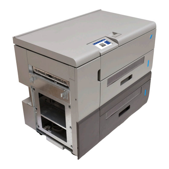
GUI. The HCI3500 contains two paper trays and a paper bypass route, which allows for custom sequencing of sheets from three different sources (the two trays and the printer output). -
Page 10: Guide To Components
Guide To Components HCI3500 Exit Area Ultrasonic Double Sheet Docking Plate Detection (DSD) Sensor Exit Side Cover Plate (Q102/202) Upper Tray / Tray A Tray Empty Sensors Lower Tray / Tray B (Q105/Q205) Front Door Rear Paper Guide (RPG) Jam Clearance Baffles (blue) - Page 11 Guide To Components (Continued) HCI3500 Top View Top cover removed for clarity Exit Sensor (Q303) Paper Infeed Sensor (Q310) Paper Path Detection Sensor (Q311) Bypass Baffle Bypass Baffle, Infeed Bypass Baffle, Exit Exit Module (not visible, located under the baffle)
- Page 12 Guide To Components (Continued) HCI3500 Upper Support Assembly Top tray removed for clarity Ultrasonic Distance Sensor (USDS) (Q301/302) Upper Support Assembly...
-
Page 13: User Interface
(GUI) / Control Panel which allows for viewing or adjusting local machine settings and properties. In other configurations where the HCI3500 is connected to an upstream printer or device, setting up a job will be handled via the UI of the upstream device. - Page 14 The Job sub-menu allows for programming of jobs when the HCI3500 is used as primary feeder. If the HCI3500 is connected to an Upstream Printer or other device, jobs will be programmed using the user interface of the upstream device and the HCI3500 Jobs sub-menu will be disabled.
-
Page 15: Basics
The HCI3500 contains two power switches (Service and Main). The default position for the Service Power Switch is ‘off’. If the Service Power Switch is ‘on’, the HCI3500 will be able to power up as a standalone unit, but will ignore power on signals from upstream devices. -
Page 16: Calibration
Calibration Sensor Calibration The HCI3500 has two types of double sheet detection (DSD): optical and ultrasonic. The machine also contains a Ultrasonic Distance Sensor (USDS). If feed errors begin occuring more frequently, these sensors may need to be calibrated. Refer to Section 6 for full cali- bration details and instructions. -
Page 17: Job Preparation
Job Preparation Paper stack preparation Hold the paper stack on a flat surface as shown Bend the paper stack Use your fingers and thumbs to pinch the paper stack With the paper pinched between your fingers, straighten out the paper stack Continued on next page... - Page 18 Paper stack preparation (continued) Flex the paper back and forth a couple of times to break surface tension and preseparate the sheets Realign the sheets into a stack before putting them into the tray...
-
Page 19: Measuring The Paper Curl
Measuring the paper curl Take a sample of the stack (about 15 mm / 0.59” high) and place it on a flat surface Take the midpoint as reference and do all the measurements within the marked area of the picture (from the center to the leading edge in paper Measure within this area feed direction) -
Page 20: Loading Paper
Myriad Pro, Semi Bold Material Adhesive Notes McDermid Autotex Velvet V207 3M 468MP 0,127mm Dim. Gen. tol. Scale Form Art. no. Rev. dat. PS 1 Title Design dat. 2016-11-14 HCI3500 Tray Paper Alignment Label Doc. No. 131-110717B Continued on next page... - Page 21 Loading Paper (continued) The Vacuum Size Valve controls the size of the vacuum suction area on the bottom of the vacuum chamber.The Vacuum Size Valve needs to be manually shifted to the correct position, which depends on paper width. If paper width is greater than 188 mm, the lever needs to be positioned as shown.
- Page 22 Page intentionally blank.
-
Page 23: Setting Up A Job
The Job sub-menu allows for programming of jobs when the HCI3500 is used as primary feeder. If the HCI3500 is connected to an Upstream Printer or other device, jobs will be programmed using the user interface of the upstream device. -
Page 24: Auto Fans / Manual Fans
Auto mode sets all the process parameters except for the paper color, which is set in the [Advanced] sub-menu, and the paper curl amount. Plockmatic always recommends to use all auto/default settings. Paper Curl This parameter allows the user to select the curl amount of the loaded paper. -
Page 25: Dsd Sensors
DSD Sensors Ultrasonic DSD Sensor [A] The HCI3500 is equipped with two independent double sheet detection systems, both optical and ultrasonic. The ultrasonic sensor is active by default. Optical DSD Sensor The HCI3500 is equipped with two independent double sheet detection systems, both optical and ultrasonic. -
Page 26: Advanced
If automatic settings provide unsatisfactory results, fan settings may be adjusted manually. Plockmatic recommends adjusting only one setting at a time. If adjusting that setting does not provide satisfactory results, set it back to auto mode prior to adjusting another setting. - Page 27 Manual Fans Adjustment (continued) F.F. R.F. V. Air S. Air F.F. R.F. Separation Air The Separation Air Fan blows air underneath the transportation belts at the leading edge of the paper stack to maintain paper separation during feeding. Front Float Air This parameter controls the flow of the two front fans (closest to the transportation belt).
- Page 28 Manual Fans Adjustment (continued) Rear Float Air This parameter controls the flow of the two rear fans. Float air blows into the paper stack from the sides to create separation between sheets. Vacuum Air This parameter controls the vacuum fan, which pulls paper towards the transportation belt during feeding.
-
Page 29: Process Position
Process Position This parameter controls the position of the top of the unseparated paper stack. The Process Position value corresponds to a position on the SP Sensor, which the operator can see via a label on the case of the SP Sensor. Process Position Process Position Label... -
Page 30: Saving Changes
Stack of unseparated paper Testing the changes Before starting a job, Plockmatic recommends testing the changes made in manual mode with the “test settings” button under the Tools Menu (see section 3 of this manual). This function activates all the fans and moves the elevator to process position according to your settings. -
Page 31: Tools
3. Tools The Tools Menu From the Tools sub-menu the user can modify parameters such as Units and Language. This sub-menu also allows the user to test the manual settings, calibrate sensors, enter service mode and check the Software version. Units Toggle between millimeters or inches by pressing the [Units] button. -
Page 32: Test
Test The [Test Settings] button is used to check the manual settings. Press this button once to activate all the fans and move the elevator to process position. Press this button twice to switch off the fans and to move the elevator down. -
Page 33: Software Version
Software version This function allows the user to check the Software version installed on the HCI3500. - Page 34 Page intentionally blank.
-
Page 35: Jobs
The Job sub-menu allows for programming of jobs when the HCI3500 is used as primary feeder. If the HCI3500 is connected to an Upstream Printer or other device, jobs will be programmed using the user interface of the upstream device and the HCI3500 Jobs sub-menu will be disabled. -
Page 36: Saving A Job
Saving a Job After having selected the Job from the job list, push the [Save] button to save changes to it. Push [Yes] to confirm. NOTE: Before saving a Job, make sure to have pressed the green checkmark button on the Settings sub-menu (see “saving changes”... -
Page 37: Clearing Misfeed(S)
5. Clearing Misfeed(s) Clearing Misfeed(s) Misfeed / Jam in Feeder Tray The affected tray will unlock. Pull out the tray If the sheet has been misfed and isn’t damaged, reposition and restart If sheet(s) are damaged, make sure to remove the complete set so that the next booklet will be correct Misfeed / Jam in Paper Transport Area Open the front door... - Page 38 Misfeed / Jam in Infeed / Bypass Area (continued) If the stuck paper is still not reachable after having opened the Top Cover, it might be necessary to open either the Infeed Baffle [A] or the Exit Baffle [B]. Open the top cover Open the Infeed Baffle Remove misfed sheet(s) and clear area of any debris or obstructions Top cover removed for clarity...
-
Page 39: Troubleshooting
HCI3500 Fault codes General When there is a misfeed or fault condition in the HCI3500, a message and fault code will be displayed on the GUI. Some fault codes may be rectified by the operator, but some fault codes may only be rectified by an authorized technician. -
Page 40: Hci3500 Fault Codes
HCI3500 Fault Codes NOTE: For sensor locations, refer to to the Guide to Components section in this manual. HCI-100/200 Misfeed Tray A/B Misfeed is a paper flow error detection. Misfeed checks if a sheet is moved correctly from paper pile to optical DSD sensor. Time is measured from the start of the drive roller (used to feed and separate a sheet from the paper pile) until the optical DSD sensor can see the leading paper edge. - Page 41 HCI3500 Fault Codes (Continued) NOTE: For sensor locations, refer to to the Guide to Components section in this manual. HCI-104/204 Too Thick, Tray A/B Too Thick is a paper thickness error detection. Too Thick checks if a sheet is too thick when it passes the optical DSD sensor Q101/201.
- Page 42 HCI3500 Fault Codes (Continued) NOTE: For sensor locations, refer to to the Guide to Components section in this manual. HCI-108/208 Too Thin, Tray A/B Too Thin is a paper thickness error detection. Too Thin checks if a sheet is too thin when it passes the optical DSD sensor Q101/201.
- Page 43 HCI3500 Fault Codes (Continued) NOTE: For sensor locations, refer to to the Guide to Components section in this manual. HCI-301 Exit Error Exit Error is a paper flow error detection. Exit Error checks if a sheet has moved past the Exit sensor Q303 correctly.
-
Page 44: Jam Recovery Manual Setting
Increase both front and rear float air by 10% and check if sheets are floating correctly. Sheets are floating correcly Exit Repeat the procedure until sheets float correcty. If the HCI3500 is set correctly, the sheets will be floating horizontally with equal amounts of separation between sheets. •... -
Page 45: Jam, Too Long, Too Thick Errors
Decrease both front and rear float air by 10% and check if sheets are floating correctly. Sheets are floating correcly Exit Repeat the procedure until sheets float correcty. If the HCI3500 is set correctly, the sheets will be floating horizontally with equal amounts of separation between sheets. •... -
Page 46: Sensor Calibration
-Select Optical DSD B to calibrate the lower tray’s sensor -The selected tray opens -Open both trays of the HCI3500 and fetch the Optical DSD Calibration Strip [A] -Place the Calibration Strip as shown in the picture -Press Start Calibration -Calibration complete. - Page 47 -Select Ultrasonic DSD B to calibrate the lower tray’s sensor -The selected tray opens -Open both trays of the HCI3500 and fetch the Ultrasonic DSD Calibration Strip [B] -Place the Calibration Strip as shown in the picture. It shall be centered relative to the US DSD Sensor -Press Start Calibration -Calibration complete.
- Page 48 Page intentionally blank.
-
Page 49: Remarks
7. REMARKS Do’s And Don’ts • Always follow all warnings marked on, or supplied with, the equipment. • Always exercise care in moving or relocating the equipment. Caution Unplug the power cord from the wall outlet and machine before you move or relocate the equipment. -
Page 50: Where To Put Your Machine
Where to Put Your Machine Machine Environment • Always locate the equipment on a solid support surface with adequate strength for the weight of the machine • Always keep magnets and all devices with strong magnetic fields away from the machine If the place of installation is air-conditioned or heated, do not place the machine where it will be:... -
Page 51: Access To Machine
Access to Machine Place the machine near the power source, providing clearance as shown. 1. Rear: more than 600mm / 24” 2. Front: more than 600mm / 24”... -
Page 52: Maintaining Your Machines
HCI3500 Maintenance Cleaning HCI3500 An increasing number of misfeeds may indicate a need to clean the HCI3500. Clean every 50 000 cycles or when the number of misfeeds increases. Use a vacuum cleaner, towels and brushes for general purpose cleaning of the paper path, trays, etc. In addition, follow the detailed cleaning instructions below: 1. - Page 53 Cleaning HCI3500, Continued 4. Open the front door. 5. Toggle the blue handles to the baffles and clean surfaces from toner smearings. 6. Clean, if needed, the feed rollers inside the baffles with rubber reactivator alcohol.
-
Page 54: Limitations Of The Hci3500
• When loading paper in the trays of the HCI3500 make sure that its wave curl is not greater than 2 mm otherwise a paper jam might occur. •... -
Page 55: Specifications
HCI3500 OFF with printer OFF Noise emissions 67dB (A) - 85dB (C) Operating temperature 10-30°C Humidity 30-80% RH Plockmatic use open source code in parts of this product General Specifications Remarks Speed (Online usage) Maintains engine speed (actual depends of engine speed.) - Page 56 Tray Specification Specifications Remarks 3500 sheets Load capacity 80 gsm plain paper, 1750 sheets per tray Standard Paper Sizes A4, A3, B4, 8.5 x 11”, 8.5 x 14”, 11 x 17”, 12 x 18”, SRA3, SRA4, 9 x 12”, Executive, A5, 5.5 x 8.5 Custom paper size (min) 120 x 210 mm / 4.73 x 8.27 in Custom paper size (max)
- Page 57 Bypass Specification Specifications Remarks Standard Paper Sizes A4, A3, B4, 8.5 x 11”, 8.5 x 14”, 11 x 17”, 12 x 18”, SRA3, SRA4, 9 x 12”, Executive, A5, 5.5 x 8.5 Custom paper size (min) 95 x 139 mm / 3.74 x 5.47 in Custom paper size (max) 356 x 1200 mm / 14.02 x 47.24 in Minimum - Maximum paper weight...
-
Page 58: Declaration Of Conformity Hci3500
EU DECLARATION OF CONFORMITY ......N0004473 (A.2) Manufacturer ..Plockmatic International AB, Telefonvägen 30, S-126 26 Hägersten, Sweden This Declaration of Conformity is issued under the sole responsibility of the manufacturer Object of the Declaration Type/Model F131-001 Name HCI3500 Description... - Page 59 Page intentionally blank.
- Page 60 Page intentionally blank.
Need help?
Do you have a question about the HCI3500 and is the answer not in the manual?
Questions and answers