Table of Contents
Advertisement
Quick Links
Advertisement
Table of Contents

Related Manuals for Neoway N27 EVB


Summary of Contents for Neoway N27 EVB
- Page 1 EVK User Guide Issue 1.0 Date 2020-01-14...
- Page 2 THIS GUIDE PROVIDES INSTRUCTIONS FOR CUSTOMERS TO DESIGN THEIR APPLICATIONS. PLEASE FOLLOW THE RULES AND PARAMETERS IN THIS GUIDE TO DESIGN AND COMMISSION. NEOWAY WILL NOT TAKE ANY RESPONSIBILITY OF BODILY HURT OR ASSET LOSS CAUSED BY IMPROPER OPERATIONS. THE INFORMATION IN THIS DOCUMENT IS SUBJECT TO CHANGE WITHOUT NOTICE DUE TO PRODUCT VERSION UPDATE OR OTHER REASONS.
-
Page 3: Table Of Contents
N27 EVK User Guide Table of Tables Contents 1 Overview ....................1 2 About N27 EVB ..................2 3 Power and Connection ................4 3.1 Power Supply ..........................4 3.2 Communication Connection ......................4 3.2.1 M5X0-PWR Board ....................... 4 3.2.2 Micro-USB Cable ......................... 6 4 Commissioning .................. - Page 4 This means the reader be careful. In this situation, you might perform an action that could result in module or product damages. Means note or tips for readers to use the module Copyright © Neoway Technology Co., Ltd...
- Page 5 N27 EVK User Guide About This Document Related Documents Neoway_N27_Datasheet Neoway_N27_Product_Specifications Neoway_N27_HW_User_Guide Neoway_N27_AT_Command_Mannual Copyright © Neoway Technology Co., Ltd...
-
Page 6: Overview
Chapter 1 Overview 1 Overview N27 EVB is designed to commission and test the N27 module. It provides one power interface, two UART interfaces, one USB interface, one SIM card interface, two antenna interfaces, and one PWRKEY button. You can connect it to a power supply and a computer through the USB cable or serial-to-USB cable to commission the functions of the module. -
Page 7: About N27 Evb
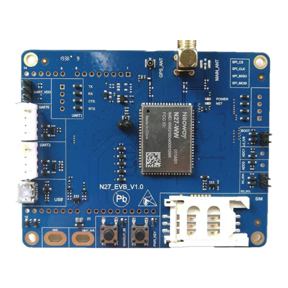
N27 EVK User Guide Chapter 2 About N27 EVB 2 About N27 EVB This chapter describes the hardware layout of the N27 EVB. Figure 2-1 Top view of N27 EVB Figure 2-2 Copyright © Neoway Technology Co., Ltd... - Page 8 In Figure 2-1, each interface and keys of N27 is marked in red rectangles. Read this user guide carefully before using N27 EVB. If necessary, please refer to the schematic diagram and PCB file of the board. Table 2-1 lists each interface or button and their functions.
-
Page 9: Power And Connection
M5X0-PWR cable and one Micro-USB cable for data communication. 3.1 Power Supply The N27 EVB provides solder pads for external power cables, as shown in Figure 3-2. The input voltage ranges from 3.1V to 4.3V and a 3.6V regulated power source is recommended. - Page 10 Chapter 3 Power and Connection M5X0-PWR is connected to the N27 EVB through 4-pin cables, which have been soldered to the power board in a sequence of red, black, yellow, and green at one end and should be inserted into the plug of the EVB at the other end.
-
Page 11: Micro-Usb Cable
N27 EVK User Guide Chapter 3 Power and Connection 3.2.2 Micro-USB Cable A micro-USB cable is used to connect N27 to a computer for USB or serial communication. Figure 3-2 USB cable Copyright © Neoway Technology Co., Ltd... -
Page 12: Commissioning
Use an external power source to supply power. Connect it to the computer through the M5X0-PWR board. Insert a SIM card and install an antenna onto the EVB board. Hold the PWRKEY_N button for 1 seconds, and the module starts up. Copyright © Neoway Technology Co., Ltd... - Page 13 Chapter 4 Commissioning Step 2: Install the PL2303 driver. Obtain the driver package from Neoway FAE or download it from the Internet if you use the serial-to-USB cable Neoway provided. Step 3: Start the Neo_ComTool and set the parameters of the serial port and AT.
-
Page 14: Through Usb Port
Step 2: Install the N27 USB drivers on your computer. If your computer runs a Windows 8.1 or Windows 10 OS, disable the signature enforcement. Decompress the N27 tool package that Neoway provides. In Device Manager, right-click one device and choose Update Driver Software from the menu. - Page 15 In the page of Browse for driver software on your computer, click Browse and choose the driver software path. For a computer running a 32-bit OS, select neoway_2019xxxx\32bit. ⚫ For a computer running a 64-bit OS, select neoway_2019xxxx\64bit. ⚫ Copyright © Neoway Technology Co., Ltd...
- Page 16 If the computer displays Windows Security, click Install this driver software anyway. The installation is completed. Repeat steps 1 to 4 to install other drivers. Step 3: Start the Neo_ComTool and set the parameters of the serial port and AT. Copyright © Neoway Technology Co., Ltd...
- Page 17 Step 5: Send AT commands to test or commission the module. You can also upgrade the firmware of the module and capture logs through the USB port. The NEOWAY HS-USB Diagnostics 8620 (COM244) will be used for upgrade or log capturing. For details, see other guides.
Need help?
Do you have a question about the N27 EVB and is the answer not in the manual?
Questions and answers