Table of Contents
Troubleshooting

Subscribe to Our Youtube Channel
Related Manuals for Tesla TI3500 GPU-24


Summary of Contents for Tesla TI3500 GPU-24
- Page 1 Power Anytime, Anywhere Tesla TI3500 GPU-24 ™ User Manual Built Smart...Proven Tough Tesla Industries, Inc. 101 Centerpoint Blvd. New Castle, DE 19720 (302) 324-8910 Phone (302) 324-8912 Fax www.teslaind.com www.tesla1.com...
- Page 2 Conditioners, manufactured by Tesla™ Industries, Inc., are able to safely and effectively charge any AGM, Lead Acid battery. The Tesla™ GPU’s and chargers are voltage and current regulated to 0.01% (dual loop). The charging voltage is calibrated, by Tesla™, to 28.6 volts and is pure dc (no power line ripple).
- Page 3 Chemical Family/Classification: Tesla™ Industries, Inc. Sealed Lead Battery Synonyms: Telephone: Sealed Lead Acid Battery, VRLA Battery For information, contact Tesla™ Industries, Inc. Manufacturer's Name/Address: Customer Service Department at 302-324-8910 Tesla™ Industries, Inc 101 Centerpoint Blvd. 24-Hour Emergency Response Contact: New Castle, DE 19720-4180...
- Page 4 Supersedes: AF ECO #: 1002195 Inorganic lead and sulfuric acid electrolyte are the primary components of every battery manufactured by Tesla™ Products. There are no mercury or cadmium containing products present in batteries manufactured by Tesla™ Products. IV. FIRST AID MEASURES Inhalation: Sulfuric Acid: Remove to fresh air immediately.
-
Page 5: Table Of Contents
3.5 – Engine Starting Power 3.6 – Temperature Specifications 3.7 – Environmental 3.8 – Pre-Operation 3.9 – Transporting Unit 3.10 – Regulated 28.5 Vdc Output Ground Power 17-18 3.11 – Regulated AC Power Section 4 – Post Operation 4.1 – General TI3500 GPU-24... - Page 6 8.1 – Shipping Case 8.2 – GPU Protective Covers 8.3 – Tesla™ AC Line Cords 8.4 – Tesla™ Universal AC Line Cords 8.5 – TI25000-U00 Unit Modification/Universal Line Cord Set 8.6 – Line Cord AC Adapter 8.7 – Cobra™ DC Replacement Contacts and Tools 8.8 –...
- Page 7 Abbreviations and Symbols Abbreviations that may be used within the text, headings and titles of this manual. LIST OF ABBREVIATIONS Abbreviation Defi nition Alternating Current Airfl ow Technology American Wire Gauge amp or A Ampere cont Continuous °C Degree Celsius °F Degree Fahrenheit Direct Current...
-
Page 8: Section 1 - Safety Review
The following symbols will appear within the warning triangles to alert the user to the specifi c type of danger or hazard. General Warning Electrical Hazard Explosion Hazard Fire Hazard Battery Warning Guard from Moisture Figure 1.2.1 – Different types of hazard and caution symbols TI3500 GPU-24... -
Page 9: Hazards
(outlined in blue) to ensure the switch setting (115V or 230V) matches the ac power source (hangar wall, fl ight line ac power) prior to connecting the unit for recharging. Figure 1.3.4 – TI3500 GPU-24 Input Voltage Selector Switch TI3500 GPU-24... -
Page 10: Important Safety Precautions
150°F (65°C). This protects the unit from overheating and damage. If the unit shuts down, move the unit into a cooler environment such as shade or air conditioning when possible. Perform a full function test, after the unit has been allowed to cool, prior to use. TI3500 GPU-24... -
Page 11: Section 2 - Product Overview
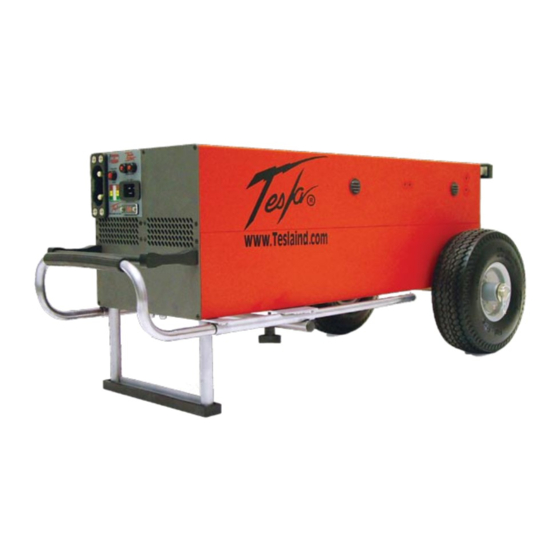
Section 2 – Product Overview 2.1 – Introduction Thank you and congratulations on the purchase of your new TI3500 GPU-24 Ground Power Unit. The TI3500 GPU-24 provides dc electrical ground power for aircraft flight line, maintenance and ground support operations. The unit is designed to provide 24 volt dc output for aircraft and vehicle engine starting and 24 or 28.5 volts dc output for ground maintenance, avionics/electrical trouble shooting and testing. -
Page 12: General Specifications
-40°C to +55°C (-40°F to 131°F) with ac power Storage Temperature: • -65°C to +105°C (-85°F to 221°F) Cell Capacity: • +40°C 110% ± 05% • +25°C 100% ± 05% • +00°C ± 05% • -20°C ± 10% • -40°C ± 10% TI3500 GPU-24... -
Page 13: Front Panel Overview
- Allows Unit to operate charge state/power output status. within voltage range of either 100-130 Vac or 200-260 Vac. Air Intake Ports – Provide airflow for cooling internal electronics. Telescoping Handle – Allows for easy transport of unit. TI3500 GPU-24... -
Page 14: Universal Front Panel Overview
Vac line voltage or 200-260 Vac line voltage. 24 Vdc Capacity Meter – Indicates the 24V battery Telescoping Handle – Allows for easy transport of unit. charge state/power output status. Air Intake Ports – Provide airflow for cooling internal electronics. TI3500 GPU-24... -
Page 15: Physical Dimensions
CAUTION that ports are clear at all times. When the TI3500 GPU-24 is plugged into single-phase 100-260 Vac, 50/60 Hz ac power, the internal cooling system will efficiently regulate unit temperature regardless of load. At room temperature (+77°F) the exhaust air will not exceed the ambient temperature by more than 5°F. -
Page 16: Operating Positions
Product Overview 2.8 – Operating Positions The TI3500 GPU-24 can be operated in both the horizontal (Figure 2.8.1) and vertical (Figure 2.8.2) positions as shown. Make sure that the airflow is not obstructed from air intake (figure 2.8.3) and outlet (Figure 2.8.4). -
Page 17: Input Voltage Selector Switch
The 230 Vac setting accommodates the voltage range of 200-260 Vac. If the Unit has been modified with a Universal AC Input Receptacle, the NOTE Input Voltage Selector Switch will not be incorporated on the front panel. Figure 2.9.2 Unscrew Protective Cover Figure 2.9.3 Select Voltage TI3500 GPU-24... -
Page 18: Push To Test" Button And Led Status Indicator
(If this sensor is tripped, allow ten minutes for unit to cool cool before operating “Push to Test” button.) before operating “Push to Test” button.) Figure 2.10.1 “Push to Test” button location Figure 2.10.2 Pushing to Test (outlined in blue) STATUS STATUS STATUS Full Charge Half Charge No Charge TI3500 GPU-24... -
Page 19: Ac Input Circuit Breakers
Reset breaker by pressing red button. Reconnect ac and dc connections to the unit. The unit should power up automatically. If the breakers continue to trip, return the unit to Tesla™ Industries for repair. Figure 2.11.1 - AC Input Circuit Breakers Figure 2.11.2 - Pressing Circuit... -
Page 20: Section 3 - Operating Procedures
1200 - 1500 peak starting amps 40-50% charged 1500 - 1800 peak starting amps 50-60% charged 1800 - 2100 peak starting amps 60-70% charged TI3500 GPU-24 2100 - 2400 peak starting amps 70-80% charged 2400 - 3000 peak starting amps 80-100% charged... -
Page 21: Temperature Specifications
If the unit shuts down, move the unit into a cooler climate, such as shade or air conditioning when possible. Perform a full function test prior to use after the unit has been allowed to cool. TI3500 GPU-24... -
Page 22: Environmental
If the unit is exposed to signifi cant moisture, preventive measures and precautions shall be taken to: A. Prevent accumulation of moisture on ac and dc connectors/receptacles Figure 3.7.1 TI3500 GPU-24 with raincover. See page 35 for details. B. Minimize moisture entering forward inlet and outlet cooling fan vent ports When not in use, unit inlet and outlet vent ports shall be covered from exposure. -
Page 23: Pre-Operation
3.9 – Transporting Unit The TI3500 GPU-24 has a telescoping handle that makes rolling the unit easy. For transporting on uneven ground, axle extensions should be added to the unit. For use on sand, balloon tires should be installed on the unit (see Optional Accessories). -
Page 24: Regulated 28.5 Vdc Output Ground Power
Ensure dc power cable plug is fully seated into the GPU’s DC Battery Receptacle. The unit is now ready to safely transfer power. Figure 3.10.1 Attaching DC Power Cable to TI3500 GPU-24 Figure 3.10.2 DC Power Cable Attached Connecting DC Power Cable To Vehicle or Aircraft Line up the NATO plug or aviation dc plug pins and push it in. - Page 25 50 amps. Engine Starting CAUTION Unplug ac power cord before starting engine with TI3500 GPU-24 Prior to engine start, ensure power cell charge is sufficient to provide an efficient engine start. Figure 3.10.5 Starting Fire Scout with Figure 3.10.6 Starting Vehicle with...
-
Page 26: Regulated Ac Power
Plugging in with AC Power When the TI3500 GPU-24 is plugged into ac power, the output is 28.5 volts. This voltage allows the system to recondition and recharge the vehicle’s battery(ies). It is also an optimum voltage for powering avionics and lighting on most aircraft. -
Page 27: Section 4 - Post Operation
Section 4 – Post Operation 4.1 – General Although the TI3500 GPU-24 has been ruggedized and made weather resistant within the scope of unit’s intended use, it is essential that good general care be taken to maintain unit in good operating condition and to maximize unit’s operational life. - Page 28 The TI3500 GPU’s power cells may be damaged if recharged by NiCad or Lithium Ion battery chargers. Power cells should only be charged by either the TI3500 GPU’s internal charger and the ac power cord furnished with the equipment, or when connected to aircraft’s external dc power receptacle. Figure 4.3.3 Proper and Improper Charging Methods TI3500 GPU-24...
-
Page 29: Section 5 - Unit Care And Maintenance
Avoid Prolonged Exposure to Extremely Damp Environments Be sure to disconnect ac power from the ac source if the TI3500 GPU-24 has come into contact with water. If the AC Input Circuit Breaker has tripped due to water infiltration, allow the unit to dry out before attempting to reset circuit breaker. -
Page 30: Unit Servicing
Ensure proper packaging when returning the unit. Transport the unit only in a sturdy shipping crate or Tesla™ Shipping Case. It is important to enclose the Repair Request Form. Seal the crate on all sides and return it to Tesla™ at the address listed below. Please contact Tesla™ Customer Service at (302) 324-8910 with any questions or concerns. -
Page 31: Normal Functional Test Procedures
Check Unit for Evidence of Damage Check for dents, punctures, case distortion or misalignment, and cracked or loose connec tors. If no damage is evident, proceed to the next step. If damage is evident, contact Tesla™ Industries, Inc. Figure 5.5.1 – Digital Multimeter Check DC Voltage Reading at DC Receptacle Terminals To verify that the power cells are fully charged, set the digital multimeter to measure dc voltage. - Page 32 Move the negative probe to the DC Move the positive probe to the DC negative post. Multimeter should positive post. Multimeter should read 0 Volts. read 0 Volts. TI3500 GPU-24...
- Page 33 Pins “J,L” M to Case/GND = Open/ MΩ Figure 5.5.3 – AC Input Connector wiring diagram K to Case = Open/ MΩ J and L to Case = Less than 1 Ω A and H to Case = Open/MΩ TI3500 GPU-24...
-
Page 34: Section 6 - Troubleshooting And Faq
5. Will a Tesla™ Turbo Start™ spool up a turbine engine? Nothing will start a turbine engine faster or safer than the right Tesla™ Turbo Start™. Not only will it eliminate hot starts, but it will extend the life of your starter, your engine and your battery while reducing maintenance. The Turbo Start™ senses the impedance from the starter/generator. - Page 35 Unit should never be allowed to discharge fully. In-fi eld use, it receives a dc back charge directly from a running engine. When not in use, unit should be plugged into ac power (outlet) all the time. Tesla™ systems will retain 80% of their capacity after one year of storage.
-
Page 36: Basic Usage/Operation Questions
Reset breaker by pressing red button. Reconnect ac and dc connections to the unit. (Plug in ac line cord on military unit.) The unit should power up automatically. If the breaker continues to trip, return the unit to Tesla™ Industries for repair. TI3500 GPU-24... -
Page 37: Basic Troubleshooting
If LEDs still do not illuminate, Please contact Tesla™ Customer Service at (302) 324-8910. 2. Unit has no output dc or ac Units cells completely dead. Do a function check with digital meter, input or both. - Page 38 Switch breaker to ON position. Reconnect unit to cables and run. If LEDs still do not illuminate, Please contact Tesla™ Customer Service at (302) 324-8910. 8. Unit does not put out 28.5 Unit is not plugged in. Plug unit into ac power source to volts dc power.
-
Page 39: Section 7 - Performance Data
These differences, however, are considered insignifi cant and are not individually accounted for. Ground Support and Aircraft Instrument Variations: The data shown in the performance charts do not account for instrument tolerance differences or inaccuracies. TI3500 GPU-24... -
Page 40: Temperature Conversion Chart
152.6 -31.0 -23.8 35.6 35.0 95.0 68.0 154.4 -30.0 -22.0 37.4 36.0 96.8 69.0 156.2 -29.0 -20.2 39.2 37.0 98.6 70.0 158.0 -28.0 -18.4 41.0 38.0 100.4 71.0 159.8 Figure 12.6.1 – Temperature conversion from Celsius to Fahrenheit. TI3500 GPU-24... -
Page 41: Output Voltage
* * * * * * * * * * * * * * * * * * * * (-29 C Temp) 1050 SECONDS Calculations based on actual test data at Pratt-Whitney Canada on 30 March 1992. TI3500 GPU-24... -
Page 42: Section 8 - Optional Accessories
8.1 – Tesla™ AC Line Cords The optional Shipping Case is the safest way to transport the TI3500 GPU-24. This custom case weighs 73 lbs and comes AC line cords come in several lengths or can be custom-ordered to fi t your needs. Tesla™ specializes in equipped with side handles and locking latches. -
Page 43: Tesla™ Universal Ac Line Cords
8.4 – Tesla™ Universal AC Line Cords AC line cords come in several lengths or can be custom-ordered to fi t your needs. Tesla™ specializes in outfi tting cables with a variety of connectors and junction boxes. Contact Tesla™ customer service to fi nd out more about our selection of cords. -
Page 44: Cobra™ Dc Replacement Contacts And Tools
A rugged combination of advanced composite materials and corrosion-resistant alloys make each plug maximized for durability and connectivity. To extend the life of the Cobra™ Connector included with your unit, replacement contacts, posts, noses and tools can be ordered through the Tesla™ Customer Service. TI2005-238 TI2005-078 Cobra™... - Page 45 APPENDIX A OPTIONAL LINE CORDS FOR WORLDWIDE OPERATIONS COUNTRY VOLTS TESLA™ PART # Afghanistan TI25000-004 Old British Line Cord Algeria TI25000-004 Old British Line Cord American Samoa TI25000-011 Australian Line Cord Angola TI25000-003 Continental European Line Cord Anguilla (U.K.) TI25000-005 United Kingdom Line Cord...
- Page 46 APPENDIX A (Cont.) OPTIONAL LINE CORDS FOR WORLDWIDE OPERATIONS COUNTRY VOLTS TESLA™ PART # Ecuador TI25000-001 North American Line Cord Egypt TI25000-003 Continental European Line Cord El Salvador TI25000-001 North American Line Cord England TI25000-005 United Kingdom Line Cord Equatorial Guinea...
- Page 47 APPENDIX A (Cont.) OPTIONAL LINE CORDS FOR WORLDWIDE OPERATIONS COUNTRY VOLTS TESLA™ PART # Laos TI25000-001 North American Line Cord Latvia TI25000-003 Continental European Line Cord Lebanon TI25000-003 Continental European Line Cord Lesotho TI25000-004 Old British Line Cord Liberia TI25000-005 United Kingdom Line Cord...
- Page 48 APPENDIX A (Cont.) OPTIONAL LINE CORDS FOR WORLDWIDE OPERATIONS COUNTRY VOLTS TESLA™ PART # Romania TI25000-003 Continental European Line Cord Russia TI25000-003 Continental European Line Cord Rwanda TI25000-003 Continental European Line Cord Saudi Arabia 50/60 TI25000-003 Continental European Line Cord...
- Page 49 APPENDIX A (Cont.) UNIVERSAL LINE CORD KIT FOR WORLDWIDE OPERATIONS NOTE: TESLA™ UNIVERSAL AC LINE CORD KIT, P/N: TI25000-U00, IS FOR UNITS ORIGINALLY BUILT WITH THE UNIVERSAL AC LINE CORD OPTION ONLY. THE AC ADAPTER OPTION IS TESLA™ P/N TI16000-19 AND MUST BE ORDERED WITH THE ORIGINAL PROCUREMENT OF UNIT(S).
-
Page 50: Repair Request Form
Email: _______________________________________________________________________________________ Purchase Order #: ______________________________________________________________________________ Model #: ____________________________________ Serial #: ________________________________________ Model #: ____________________________________ Serial #: ________________________________________ Shipping method to Tesla™: ______________________________________________________________________ Description of shipping package: ________________________________________________________________ Description of problem: _________________________________________________________________________ _________________________________________________________________________________________________ _________________________________________________________________________________________________ _________________________________________________________________________________________________ Return to Tesla™ 101 Centerpoint Boulevard, New Castle, DE 19720 Attention: Repair Department... - Page 51 Tesla™ 101 Centerpoint Blvd. New Castle, DE 19720 USA Tel: 302-324-8910 Fax: 302-324-8912 9475 Double R Blvd., Suite 2 Reno, NV 89521 Tel: 775-622-8801 Fax: 775-622-8810 www.teslaind.com ♦ www.tesla1.com...
Need help?
Do you have a question about the TI3500 GPU-24 and is the answer not in the manual?
Questions and answers