Table of Contents
Advertisement
Quick Links
Advertisement
Table of Contents

Subscribe to Our Youtube Channel
Related Manuals for Security Tronix ST-POE24M


Summary of Contents for Security Tronix ST-POE24M
- Page 1 ST-POE24M INSTALLATION MANUAL www.nacebrands.com www.securitytronix.com...
-
Page 2: Table Of Contents
2.3.3 Cabinet Configuration ..........................7 2.3.4 Power Requirements ..........................8 2.4 Installation Tools and Device ..........................8 Chapter 3 Installing the ST-POE24M Switch ......................... 9 3.1 Installation Flow of ST-POE24M ..........................9 3.2 Installing the Chassis of the Switch ........................9 3.2.1 Installing the Machine Box on the Desk .................... -
Page 3: Chapter 1 St-Poe24M Switch
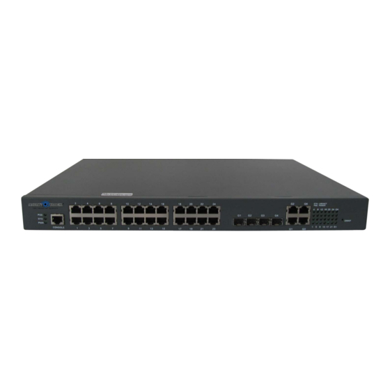
SFP port: having LINK/ACT indicators Console port An RJ45 port with a rate of 9600 bps Additionally, ST-POE24M has a grounding column, a socket and a power switch at its rear panel. Figure 1-1 Front template of the ST-POE24M switch Table 1-2 Parts at the front template of the ST-POE24M switch Abbrev. - Page 4 POE mode of the indicator If you leave the key alone for 30 seconds in POE mode, the indicator automatically enters the normal mode. Figure 1-2 Rear template of the ST-POE24M switch - 2 -...
-
Page 5: Characteristic Parameters Of St-Poe24M
ST-POE24M Hardware Installation Manual Table 1-3 Parts at the rear template of the ST-POE24M switch Abbrev. Name Description None Grounding Properly ground the system. column None ON means activating power, while Power switch OFF means disabling power. None AC power socket... -
Page 6: Rohs Description
ST-POE24M Hardware Installation Manual 1.3 ROHS Description - 4 -... -
Page 7: Chapter 2 Installation Preparation
Similar to other electronic products, the semiconductor chip easily gets damaged if you power on and off abruptly and frequently. To restart the ST-POE24M, you have to toggle the power switch three or five seconds after the power is turned off. -
Page 8: Safety Principles For Live Working
ST-POE24M Hardware Installation Manual Pull out the AC power socket and close the direct-current power before operating on the chassis or working beside the power source. The final configuration of the switch must comply with relative national laws and regulations. -
Page 9: Requirements For Common Locations
ST-POE24M Hardware Installation Manual static-proof hand ring. If there is no hand ring, use the metal clip with the metal cable to clip the unpainted metal part of the chassis. In this case, the static is discharged to the ground through the metal cable of the clip. You can also discharge the static to the ground through your body. -
Page 10: Power Requirements
2.4 Installation Tools and Device The tools and devices to install the ST-POE24M switch are not provided by the ST-POE24M switch. You yourself need to prepare them. The following are the tools and devices needed for the typical installation of the ST-POE24M switch: ... -
Page 11: Chapter 3 Installing The St-Poe24M Switch
ST-POE24M Hardware Installation Manual Chapter 3 Installing the ST-POE24M Switch Caution: Only professionals are allowed to install or replace the ST-POE24M. 3.1 Installation Flow of ST-POE24M 3.2 Installing the Chassis of the Switch The chassis of the switch can be installed on the desk or can be fixed to other cabinets. -
Page 12: Installing The Machine Box On The Desk
ST-POE24M Hardware Installation Manual 3.2.1 Installing the Machine Box on the Desk The ST-POE24M switch can be directly put on smooth and safe desk. Note: Do not put things weighing 4.5 kg or over 4.5 kg on top of the switch. - Page 13 ST-POE24M Hardware Installation Manual through a console cable, you can configure and monitor the switch of ST-POE24M by running a terminal emulation software, such as super Windows terminal. The cable is provided according to the host. The communication parameters of the terminal serial port can be set to a rate of 9600bps, eight data bits, one stop bit, no sum check bit and traffic control.
-
Page 14: Connecting Fast-Ethernet Interface
Otherwise, the single-pass problem will arise on the super terminal. The cable is used to connect the console port of the ST-POE24M switch and the outside console terminal device. One end of the cable is a 8-pin RJ45 plug and the other end is a 9-hole plug (DB9). - Page 15 ST-POE24M Hardware Installation Manual Figure 3-6 RJ-45 connector of the console port ST-POE24M Because 10/100Base-TX ports support MDI/ ST-POE24M MDIX auto-identification cable, adopt five classes of direct-through/cross network cables when it connects other Ethernet terminals. Figure 3-7 Connecting the 10/100Base-TX port and other Ethernet terminals...
-
Page 16: Connecting The 1000M Ethernet Port
ST-POE24M Hardware Installation Manual Figure 3-8 Connection method for five classes of direct-through cables Note: The colour arrangement complies with EIA/TIA 568A. Figure 3-9 Connection method for five classes of cross cables Note: The definition of the cable’s color complies with EIA/TIA 568A. - Page 17 ST-POE24M Hardware Installation Manual To use the electrical port, you can connect the electrical port and other Ethernet devices with the direct-through or cross cable through the UTP port. In this case, the corresponding optical port cannot be used. The numbering order of the pins in the UTP port is the same as the console port.
-
Page 18: Checking After Installation
ST-POE24M Hardware Installation Manual of the data Receiving normal RXD2+ Input phase of the data Receiving the paraphase RXD1- Input of the data The direct-through or cross network cable has the function of auto-identification, so the five classes of direct-through/cross network cables can be used to connect other Ethernet devices. -
Page 19: Chapter 4 Maintaining The Switch
ST-POE24M Hardware Installation Manual Chapter 4 Maintaining the Switch Caution: Before opening the chassis, make sure that you have released the static you carried and then toggle the power of the switch. Before operating any step in Appendix B, read the section “Safety Advice”. -
Page 20: Closing Chassis
ST-POE24M Hardware Installation Manual After taking off the cover, put it horizontally and avoid it being crushed or damaged. Otherwise, the chassis will be hard to install. 4.2 Closing Chassis The section mainly describes how to put the cover and close the chassis. Do as follows: ... -
Page 21: Chapter 5 Hardware Fault Analysis
9600 bps, eight data bits, no sum check bit, one stop bit and no traffic control. 5.2 Indicator Description The LED indicator shows that the switch is running. The following table shows the indicators of the ST-POE24M switch and their description: - 19 -... - Page 22 ST-POE24M Hardware Installation Manual Abbrev. Name Description If the switch is powered on, the indicator Power indicator is on. If the indicator is always on, the system is being started. System indicator If the indicator flickers, the system works normally.
- Page 23 SECURITYTRONIX PoE Switch 1-Year Limited Warranty SECURITYTRONIX. (the "Company") warrants to the Original Purchaser that the ST-POE ethernet series switch purchased is free from defects in workmanship or material under normal use. This warranty starts on the date of shipment of the hardware to the Original Purchaser. During the warranty period, the Company agrees to repair or replace, at its sole option, without charge to Original Purchaser, any defective component.
Need help?
Do you have a question about the ST-POE24M and is the answer not in the manual?
Questions and answers