
Related Manuals for Tandon TM100-1

Summary of Contents for Tandon TM100-1
- Page 1 O E M OPERATING AND SERVICE MANUAL TM100-1, TM100-2 DISK DRIVES 48 TRACKS PER INCH landon c o r p o r a t io n 20320 PRAIRIE STREET CHATSWORTH, CALIFORNIA 91311 © COPYRIGHT 1983 TANDON CORPORATION...
- Page 2 NOTICE This document, and the information contained herein, is copyright by Tandon Corporation and may not be duplicated or reproduced, in whole or in part, without the prior written approval of Tandon Corporation. This document is intended to provide the user with detailed information adequate for the efficient installation, operation, and service of the equipment involved.
- Page 3 C O N T E N T S Section Page Number Title Number SECTION 1 GENERAL DESCRIPTION Introduction................Scope Of The Document .............. Purpose Of The D rive..............Major Features................ Write P rotect..............Daisy Chain Capability............. Internal Trim Erase..............Industry Standard Interface Compatibility........Track 0 Switch..............
- Page 4 C O N T E N T S Section Page Number Title Number Diskettes................Loading The Diskette .............. Write Protect Tab..............Diskette Handling and Storage............ SECTION 4 THEORY OF OPERATION Introduction................Data Recording............... Components Of The Drive ............Generate and Interpret Control Sign als..........Index Sensor...............
- Page 5 C O N T E N T S Section Page Number Title Number 5.11 Head Output Check..............5-13 5.12 Cone Centering C h eck .............. 5-14 5.13 Compliance Check and Adjustment (Single-Sided Drives)......5-15 Compliance Check ............... 5-15 Compliance Adjustment ............5-15 SECTION 6 TROUBLESHOOTING GUIDE AND REPLACEMENT PROCEDURE...
- Page 6 ILLUSTRATIONS FIGURES Figure Page Number Title Number 1- 1 Disk Drive ................2- 1 Disk Drive Outline Draw ing............3- 1 Electrical Interface Characteristics..........Control and Data Timing Requirements ........... Logic Board With Programmable Shunts and Option Patching Locations..Recording Media ..............3-10 Write Protect T a b ..............
-
Page 7: Table Of Contents
FIGURES Page Figure Number Number Title 6-16 Drive Motor Harnessing and Mounting ..........6-21 6-17 Drive Motor P ulleys..............6-22 6-18 Track 0 Cable Harnessing ............6-23 6-19 Track 0 Adjustment Screw ............6-24 6-20 Track 0 Mounting Screw............6-25 6-21 Write Protect Mounting Adjustment Screw s........ - Page 9 This document provides required information in terminals. order to evaluate and incorporate Tandon’ s disk drive into a system. Tandon Corporation’ s Model Number TM100-1 MAJOR FEATURES and TM100-2 are full-feature, 5-1/4-inch, flexi...
- Page 10 TRACK 0 SWITCH assembly and its associated electronics. This positioner uses a one-step rotation to cause a one track linear movement. The Track 0 switch is provided to generate a logic level at the drive interface, indicating the Data recovery electronics include a low-level read amplifier, differentiator, zero crossover read/write head is positioned at the outermost track.
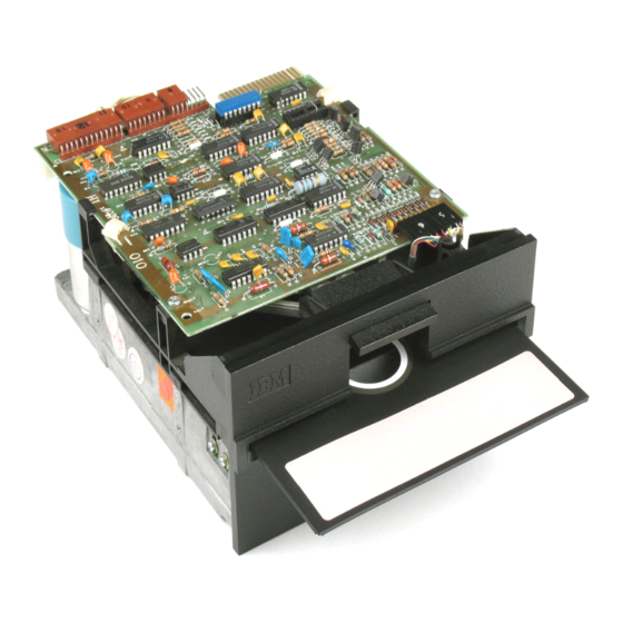
- Page 11 FIGURE 1-1 DISK DRIVE...
- Page 13 SECTION 2 PRODUCT SPECIFICATIONS INTRODUCTION This section contains the mechanical, electrical reliability, and environmental specifications for the TM100-1 and TM100-2 drives. MECHANICAL SPECIFICATIONS The physical dimensions of the drive are located in Figure 2-1. ELECTRICAL AND OPERATIONAL SPECIFICATIONS The electrical and operational specifications are located in Table 2-1 .
- Page 14 NOTES: 1. DIMENSIONS ARE GIVEN IN INCHES. METRIC EQUIVALENTS ARE IN PARENTHESES. 2. TOLERANCE ON ALL DIMENSIONS ±0.020 INCH, UNLESS OTHERWISE SPECIFIED. 3. WEIGHT IS APPROXIMATELY 3 POUNDS (1.35 KILOGRAMS). FIGURE 2-1 DISK DRIVE OUTLINE DRAWING landon 179022-001 REV. B CORPORATION, CHATSWORTH, CALIFORNIA 91311...
- Page 15 ANSI-compatible, 5-1/4-inch diskette Media Media Life (for reference only) 4 x 10 passes per track Tracks Per Inch 48 TPI, both drives Tracks Per Drive TM100-1 40 tracks TM100-2 80 tracks 0.529 millimeters, 20.8 milinches Track Spacing Head Life 20,000 media contact hours Disk Rotational Speed 300 RPM ±...
- Page 16 + 5 volts ± 0.25 volt, 600 milliamperes, + 5 volts D. C. Power average, with less than 100 millivolts peak-to-peak ripple. When prepared for shipment by Tandon, Shipment the drive meets the requirements of NSTA preshipment test procedure Project...
- Page 17 TABLE 2-3 ENVIRONMENTAL SPECIFICATIONS Temperature 10 ° C to 4 6 ° C , 5 0 ° F to 115° F Operating, media dependent Nonoperating —40 ° C to 7 1 ° C , — 40° F to 16 0° F Relative Humidity Operating, noncondensing, 20-to-80 percent...
- Page 19 This section contains information on how to unpack, check out, install, and operate the 5 . Ensure the drive belt is in place. TM100-1 and TM100-2 drives. 6 . Manually rotate the drive hub. It should rotate freely. UNPACKING THE DRIVE 7 .
- Page 20 Track 0 Write Protect Composite Read Data Spare Interface connections for the TM100-1 and TM100-2 are made via a user-supplied, thirty- four pin, flat ribbon connector, 3M Part Number 3463-0001 or Amp Part Number 583717-5, using contact Part Number 1-583616-1 for twisted INPUT CONTROL LINES pair or its equivalent.
- Page 21 The direction of motion is determined by the Although a value cannot be specified for write logic state of the Direction Select line when a precompensation, Tandon suggests a value of step pulse is issued. The motion is toward the 250 nanoseconds for systems using MFM double center of the disk if the Direction Select line is density recording format.
- Page 22 When a write protected diskette is installed in a WRITE PROTECT drive, the write electronics are disabled, irre spective of the state of the Write Enable or Side Select lines. When the Write Protect line goes true Qow), the diskette is write protected and the write electronics are disabled.
- Page 23 +5 VOLTS 150 OHMS I - ------------- 74LS04 OR EQUIVALENT + TRUE j------ D>o*— hn * --- c£>----- + TRUE TRANSMISSION LINE 10 FEET 7438 OR ^EQUIVALENT RECEIVER DRIVER FIGURE 3-1 ELECTRICAL INTERFACE CHARACTERISTICS The chassis should be connected to earth ground D.C.
- Page 24 POWER ON 100 MILLISECONDS MINIMUM DRIVE SELECT MOTOR ON 250 MILLISECONDS 200 ±3 MAXIMUM MILLISECONDS 4 $ ■ INDEX 4 MILLISECONDS* 500 NANOSECONDS MAXIMUM TRACK 0 <r 500 NANOSECONDS MAXIMUM WRITE PROTECT 4 I- SIDE SELECT 100 NANOSECONDS MINIMUM DIRECTION 4 fr 5 MILLISECONDS MINIMUM...
- Page 25 When shipped from the factory, the drive is con Write Protect Control figured with a jumper at R51,0 ohm resistor, for responds to a write protected the TM100-1 and TM100-2 drives. R51 main diskette. tains 200 milliamperes of current to the stepper Write Protect Control is motor whether or not the drive is selected.
- Page 26 PROGRAMMABLE SHUNT SOCKET (IE) ----------- W ------------ f—i HS NOT USED r-i 1 __1 1 __I L J— —i i—i —| ( —] SPARE j—i 1 —1 1 —1 HM NOT USED PROGRAMMABLE SHUNT SOCKET 1E FIGURE 3-3 LOGIC BOARD WITH PROGRAMMABLE SHUNTS AND OPTION PATCHING LOCATIONS...
- Page 27 DISKETTES DISKETTE HANDLING AND STORAGE The TM100-1 and TM100-2 drives use an It is important the diskette be handled and ANSI-compatible, 5-1/4-inch diskette. Diskettes stored correctly so the integrity of the recorded are available with a single index hole or with data is maintained.
- Page 28 3 . To avoid warping, do not store the NOTE diskette in direct sunlight. The 50-oersted level magnetizing force is reached at a distance of approximately three inches from 4. Do not use a lead pencil or a ballpoint a typical source, e.g., motors, gen pen to write on the label.
- Page 29 WRITE PROTECT TAB WRITE PROTECT TAB FIGURE 3-5 WRITE PROTECT TAB...
- Page 30 DO NOT WRITE ON THE RETURN THE DISKETTE DO NOT TOUCH PRECI TO AVOID DAMAGE TO JACKET WITH PEN OR SION SURFACE WITH THE DISKETTE AND TO TO ITS JACKET WHEN PENCIL. USE A FELT YOUR DRIVE, INSERT NOT IN USE. YOUR FINGERS.
- Page 31 SECTION 4 THEORY OF OPERATION INTRODUCTION Recording of data on a magnetic medium is based on the principles of electromagnetics. When current flows in a coil of wire it produces a magnetic field. The field is confined in a core of magnetic material around which the wire is This section contains a description on the theory wound.
- Page 32 FIGURE 4-2 FM RECORDING MAGNETIZATION PROFILES As the disk spins, the magnetic fields of the The comparator and the digitizer circuitry gen stored data pass successively under the head. erate a one microsecond Read Data pulse, corre The changing fields induce, in the head, an A. C. sponding to each peak of the Read signal.
- Page 33 COM PONENTS OF THE WRITE PROTECT SWITCH DRIVE The Write Protect signal is derived from a me chanical switch integrated into the drive, the The drive contains the electrical and mechanical switch is deactivated, causing a high signal on components required to perform four major J4, Pin 5 .
- Page 34 FIGURE 4-4 INTERCONNECT BLOCK DIAGRAM...
- Page 35 flop to be toggled, is accomplished by the two ex READ/WRITE HEAD clusive OR gates of IC 5D. These gates are con POSITIONER trolled by the Step direction line and by the state of the two flip flop outputs. The components of the drive required to position Test Point 8 is low when the carriage is posi...
- Page 36 TEST POINT 7 FIGURE 4-5 SOFT-SECTORED INDEX PULSE +5 VOLTS TRACK 0, TEST POINT 8 OVOLT +5 VOLTS TRACK 0 ADJUSTMENT MONITOR POINT IC 4B, PIN 9 OVOLT TRACKS DISKETTE STEPPER > MOTOR PHASES FIGURE 4-6 TRACK 0 TIMING...
- Page 37 READ/WRITE DATA WRITE/ERASE CIRCU ITS The write electronics consist of a write current The components of the drive required to read source, a write waveform generator, an erase and write data are: current source, the trim erase control logic, and the side select logic (Figure 4-7).
- Page 38 N INTERNAL WRITE BUSY N WRITE DATA N WRITE ENABLE N WRITE PROTECT DRIVE SELECT. FIGURE 4-7 WRITE DATA CIRCUIT BLOCK DIAGRAM...
- Page 39 NOTES: 1. t - 0 = 250 MILLISECONDS AFTER DRIVE MOTOR STARTS OR 20 MILLISECONDS AFTER LAST STEP PULSE, WHICHEVER IS THE LATEST TIME. 2. UNSYNCHRONIZED 3. 8.5 MILLIAMPERAGE PEAK TO PEAK 4. 4 MICROSECONDS MINIMUM, 8 MICROSECONDS MAXIMUM FIGURE 4-8 WRITE OPERATION TIMING DIAGRAM...
- Page 40 6 . Input diodes to the read amplifier are The drive must be in a ready condition before reverse biased by N Write to protect the reading can begin. This ready condition must he read am plifier during the write established by the user system.
- Page 41 UPPER HEAD ^ TEST POINT 1 TM100-2 ONLY ---------- ► READ ONLY READ AMPLIFIER • TEST POINT 2 AND SIDE SELECT AND LINEAR CIRCUITS PHASE FILTER LOWER HEAD TEST POINT 3 ZERO CROSSOVER TIME DOMAIN DIFFERENTIATOR DETECTOR FILTER (COMPARATOR) TEST POINT 4 DIGITIZER ►...
- Page 42 SPINDLE MOTOR CONTROL CIRCUIT the spindle motor is enabled. The potentiator provides an adjustable D. C. voltage reference to the regulator circuit for spindle speed adjust The Spindle Motor Enable signal is input via Pin ment. The tachometer signal provides feedback from the motor via Pins 1 and 2 of the servo cir...
- Page 43 SECTION 5 MAINTENANCE CHECKS AND ADJUSTMENTS INTRODUCTION 3 . Ensure the front panel is secure. 4 . Manually rotate the drive hub. It should rotate freely. This section is for the use of the OEM Repair 5 . Ensure the circuit boards are secure. and Service Departments.
- Page 44 STEPPER MOTOR SERVO JUMPER J2 POWER CONNECTOR FIGURE 5-1 LOGIC CIRCUIT BOARD WITH TEST POINTS Test equipment must be in calibration. This may 7 . Associated power and interface cables. be verified by observing the calibration due date 8 . A number 1 Phillips screwdriver. on the calibration sticker affixed to the equipment.
- Page 45 to the drive. If the check fails, measure the 3 . With a write protected diskette inserted, power supply voltages to ensure they are cor verify there is no continuity between the rect, or refer to the troubleshooting guide. two wires of Plug 8 or that there is a write protect true output to the control...
- Page 46 NUT PLATE FIGURE 5-2 WRITE PROTECT SWITCH ADJUSTMENT 5 . Observe the speed disk on the spindle RADIAL TRACK pulley under ambient fluorescent ALIGNMENT CHECK lighting. AND ADJUSTMENT 6 . Verify the 60 Hertz outer ring is stationary. The Radial Track alignment procedure locates the read/write head at the proper radial distance DRIVE MOTOR ADJUSTMENT on the hub center line, ensuring the track loca...
- Page 47 FIGURE 5-3 LOCATION OF R4 SPEED CONTROL POTENTIOMETER OUTER BARS ON BACK INNER BARS ON TIMING DISK TIMING RING USED FOR 50 Hz FIGURE 5-4 BOTTOM VIEW OF DRIVE...
- Page 48 FIGURE 5-5 HUB CENTER LINE AND TRACK LOCATION Adjust amplitude for at least four divi NOTE sions on the oscilloscope, A. C. coupled. The alignment diskette and drive must be allowed to stabilize at 2 . Apply power to the drive. room temperature for one hour NOTE before checks and adjustments...
- Page 49 11. Step the drive to Track 26 or higher; N O T E then, step it back to Track 16. The 75 percent figure is for use with an alignment diskette veri 12. Verify the Cats Eye pattern. fied against a standard alignment diskette.
- Page 50 RADIAL TRACK ALIGNMENT 16. Step the drive to Track 0; then, step it back to Track 16. ADJUSTMENT 17. Verify the Cats Eye pattern. 1 . Loosen the three module retaining 1 8 . Step the drive to Track 26 or higher; screws 1/2-tum with a 7/64-inch Allen then, step it back to Track 1 6 .
- Page 51 4 . Tum the cam screw until the Cats Eye 7 . Select Head 0 . patterns are equal in amplitude (Figure 8 . Read the trigger point to the start of the 5-6). first data pulse width (Figure 5-8). 5 .
- Page 52 N O T E The tolerance is 200 100 microseconds. ± TIME SCALE: 50 MICROSECONDS PfeR DIVISION FIGURE 5-8 INDEX-TO-DATA PULSE BACK FIGURE 5-9 INDEX SEN SOR’ S RETAINING SCREW AND ADJUSTMENT 5-10...
- Page 53 AZIMUTH CHECK Azimuth checks the read/write head’ s relative angle to the center line of the diskette. The Dysan 224/2D alignment diskette has three azi muth bursts, the first one having acceptable limits of 12 minutes; the second one, 15 minutes;...
- Page 54 5 . Step the carriage to the radial alignment track. 6 . Confirm the position by observing the Cats Eye pattern. 7 . Set up the oscilloscope to monitor the TTL signal at IC 4B, Pin 9, or at P ll, Pin 8 .
- Page 55 5.10 TRACK 0 STO P 5 . Turn the Track 0 stop screw counter clockwise two turns with a 0.050-inch ADJUSTMENT Allen wrench or a number one Phillips screwdriver (Figure 5-13). 6. Step the carriage to Track 0 , and observe the waveform.
- Page 56 Head amplitude can be verified by establishing 1 . Set up the oscilloscope: a nominal value of amplitude for the diskette on a known working drive. In all cases, amplitudes greater than 200 millivolts peak-to-peak are ac Channel A: Test Point 1 ceptable.
- Page 57 5.13 COMPLIANCE CHECK AND 5 . Select the drive. ADJUSTMENT 6 . Insert a nonwrite protected diskette. (SINGLE-SIDED DRIVES) 7 . Write a IF pattern on Track 34. Compliance is the maximized output of the head 8 . Observe the output waveform voltage. when the pressure of the felt pad is centered over the read/write gap.
- Page 58 CARRIAGE ASSEMBLY FIGURE 5-14 UPPER ARM AND SCREW S...
- Page 59 SECTION 6 TROUBLESHOOTING GUIDE AND REPLACEMENT PROCEDURE INTRODUCTION 2 . Verify there is no random electrical noise to the drive. This section is designed to help locate and cor 3 . Verify there is no radiated noise to the rect failures related to the drive. Table 6-1 is a drive.
- Page 60 TABLE 6-1 TROUBLESHOOTING GUIDE Condition Possible Cause Recommended Action Diskette not inserted. Insert Diskette. No index. Door not closed. Close door. Unit not selected. Verify unit select and jumper configuration. Index sensor not connected. Check P10. Replace index sensor. Index sensor defective. Spindle not turning.
- Page 61 TABLE 6-1 (CONTINUED) TROUBLESHOOTING GUIDE Condition Possible Cause Recommended Action Will not write. Diskette is write protected. Remove write protect tab from diskette. Interface not enabled. Verify write enable, select, and write data interface lines. Alignment is off. Verify alignment. Head(s) or write protect switch not connected.
- Page 62 TABLE 6-1 (CONTINUED) TROUBLESHOOTING GUIDE Recommended Action Condition Possible Cause No Track 0 Defective seek. See Will Not Seek or Restore. indication. Track 0 switch not connected. Check Pll. Track 0 switch not adjusted. Adjust Track 0 switch. Defective logic. Replace Logic circuit board.
- Page 63 TABLE 6-1 (CONTINUED) TROUBLESHOOTING GUIDE Condition Possible Cause Recommended Action Fails index See No Index. checks and adjustment. See Fails Centering Check. Diskette not centering. Alignment diskette defective. Verify alignment diskette and replace if necessary. Fails Track 0 switch check and adjustment.
- Page 64 TABLE 6-2 GUIDE TO CHECKS AND ADJUSTMENTS RECOMMENDED CHECKS AND ADJUSTMENTS PART OR ASSEMBLY REPLACED Drive Belt Logic Circuit Board Servo Circuit Board Cone Lever Assembly Cone Assembly Activity L.E.D. Front Panel Guide Rail Index Assembly Drive Motor Assembly Track 0 Switch Assembly Write Protect Switch Upper Arm Assembly Head Module Assembly...
-
Page 65: Drive Belt
TOOL REQUIREMENTS REPLACEMENT In addition to the tools listed in Section 5, the 1. With the shiny side inward, loop the new following tools are required for replacement of drive belt onto the small, flanged motor pulley. assemblies: 1. 0.010 to 0.025-inch feeler gauge 2. - Page 66 FIGURE 6-2 LOGIC CIRCUIT BOARD MOUNTING...
-
Page 67: Servo Circuit Board
SERVO CIRCUIT BOARD 3. Slide the circuit board toward the back of the drive about one-half inch. REMOVAL 4. Remove it from the drive. 1. Detach connectors P20 and P21 from the REPLACEMENT circuit board (Figure 6-3). 2. Remove the mounting screws and spacers 1. -
Page 68: Cone Lever Assembly
REPLACEMENT 5. Plug Connectors P21 into the bottom right-hand comer of the circuit board; plug in P20 above it. 1. Stand the drive on its front panel. 6. Check the drive motor’s speed. CAUTION CONE LEVER ASSEMBLY D o not scratch the front panel. REMOVAL 2. - Page 69 6. Cut the tie wraps holding the stepper 11. Slide the assembly toward the rear of the motor cables at the rear of the assembly drive, tilting it until the upper arm (Figure 6-5). finger is free. 7. Remove the two mounting screws and 12.
- Page 70 3. Install but do not tighten the two mount 9. Ensure the cone is centered in the shaft hole (Figure 6-6). ing screws and ground lug attaching the assembly to the rear of the chassis. 10. Tighten the two mounting screws attach 4.
-
Page 71: Cone Assembly
CONE ASSEMBLY 2. Cut the tie wraps attaching the Activity L.E.D. and the Write Protect Switch As sembly to the chassis (Figure 6-8). REMOVAL 3. Remove the retaining collar holding the 1. Remove the Logic circuit board. Activity L.E.D. to the grommet, using needle nose pliers, gently pulling the 2. - Page 72 E -R IN G C O N E S H A F T FIGURE 6-7 CONE’ S COMPONENT PARTS 6-14...
- Page 73 FIGURE 6-8 ACTIVITY L.E.D. CABLE HARNESSING FIGURE 6-9 ACTIVITY L.E.D. ASSEMBLY RETAINING COLLAR AND GROMMET 6-15...
-
Page 74: Front Panel
FRONT PANEL 2. Reinstall the two mounting screws a t taching the front panel to the chassis. REMOVAL 3. Reinstall the Activity L.E.D. 4. Install new bushings on both right and 1. Remove the Logic circuit board. left sides of the front panel over the 2. -
Page 75: Index Assembly
M O U N T IN G FIGURE 6-11 FRONT PANEL MOUNTING SCREW S 4. With a screwdriver inserted between the 3. If the right guide rail has been replaced, guide rail and the chassis, pry up, from reloop the head cable (s) over the two both ends, the guide rail that is to be guide rail posts (Figure 6-12). - Page 76 FIGURE 6-13 INDEX EMITTER SENSOR’ S MOUNTING AND CABLE HARNESSING 6-18...
- Page 77 4. Remove the mounting screw from the 3. Smooth out the cable harness. bottom of the drive, attaching the index detector sensor holder to the chassis 4. Attach the index em itter cable harness (Figure 6-14). to the Cone Lever Assembly. 5.
-
Page 78: Drive Motor Assembly
DRIVE MOTOR ASSEMBLY 4. Remove the drive belt. REMOVAL 5. Remove the mounting screws and shoul der washers attaching the Drive Motor Assembly to the chassis (Figure 6-16). 1. Remove the Logic circuit board. NOTE 2. Cut the cable harness tie wrap Connector P21 (Figure 6-15). -
Page 79: Drive Motor Harnessing And Mounting
FIGURE 6-16 DRIVE MOTOR HARNESSING AND MOUNTING 6-21... -
Page 80: Drive Motor Pulleys
REPLACEMENT 6. Attach a tie wrap to the bundle of wires located behind the drive motor. 1. Insert the pulley end of the new assembly 7. Reinstall the Logic circuit board. through the bottom of the chassis (Figure 6-17). 8. Adjust the drive motor’s speed. 2. -
Page 81: Track 0 Cable Harnessing
FIGURE 6-18 TRACK 0 CABLE HARNESSING 4. Remove the mounting screw attaching 3. Ensure there are no cables underneath the assembly to the chassis (Figure 6-20). the assembly. 5. Remove the assembly, pulling it toward 4. Install the mounting screw (Figure 6-20) the front of the drive, and slipping it out attaching the assembly to the bottom of from the adjustment screw (Figure 6-19). -
Page 82: Track 0 Adjustment Screw
FIGURE 6-19 TRACK 0 ADJUSTMENT SCREW 6-24... -
Page 83: Write Protect Switch
WRITE PROTECT SWITCH ASSEMBLY REPLACEMENT REMOVAL 1. Install the new assembly, using its mounting/adjustment screws. 1. Remove the Logic circuit board. 2. Tie wrap the bundle of wires at the back 2. Remove th e m o u n tin g /ad ju stm en t of the drive motor. -
Page 84: Write Protect Mounting Adjustment Screw S
FIGURE 6-21 WRITE PROTECT MOUNTING/ADJUSTMENT SCREW S FIGURE 6-22 WRITE-PROTECT CABLE HARNESSING 6-26... -
Page 85: Head Module Assembly
UPPER ARM ASSEMBLY 3. Reinstall but do not completely tighten (SINGLE-SIDED DRIVES ONLY) the screws. REMOVAL 4. Visually align the felt pad with the head (Figure 6-26). 1. Remove the Logic circuit board. 5. Tighten the two screws. 6. After inserting a diskette into the drive, 2. -
Page 86: Upper Arm Screws
FIGURE 6-24 UPPER ARM SCREW S 6-28... -
Page 87: Felt Pad On Upper Arm
MOUNTING FIGURE 6-26 FELT PAD ON UPPER ARM 6-29... - Page 88 REPLACEMENT 4. Remove the stepper motor cable from the cable harness. 1. Install the new assembly by placing its 5. Remove the mounting screws and flat left side against the module spring, and washers attaching the Head Module As compressing the module spring to seat sembly to the chassis (Figure 6-27).
-
Page 89: Latch Plate Assembly
6. Install the Logic circuit board. 2. Close the front latch. 3. Still holding the Cone Lever Assembly 7. Complete the checks and adjustments in Section 5. down, place the latch inhibitor on top of the assembly. LATCH PLATE ASSEMBLY 4. - Page 91 This appendix contains the recommended spare parts list and the major assembly drawings for the drive. Part numbers on this list should be used for ordering spare parts. A spare parts list with prices for parts and services is available from Tandon Corporation. Part Number...
- Page 95 APPENDIX B CIRCUIT BOARD SCHEMATICS AND DRAWINGS This appendix contains the current circuit board schematics and circuit board drawings for the TM100-1 and TM100-2 drives. Drawing Page Number Number Title 180010, REV K Logic Circuit Board Assembly Drawing B-2, B-3...
- Page 96 P A R T S L IS T R E F E R E N C E 0 0 0 9 I ! ! PA R T L IS T R EV R E M A R K S mxiiiiiuRi n r n r a N U M B E R i - - - - - - - - - - - - - - - - - - - - - —...
- Page 97 £ i » o o o o o o o o o o £ * ,c 4 T " T " T T “ * T “ T e g C 0 1 C 1 6 C *^C SC w ' C *rCr,Cr> ,C — o c r vc c vtcv tree cc^a:w o _ o u o £...
- Page 98 TABLE I [§] V E R S I O N 4 E I C R 2 4 N U M B E R I R P I I •001 O M I T O M I T 948000-002 O M I T 9 7 3 5 3 0 -151 —...
- Page 99 l a n d e i n CORPORATION LOGIC CIRCUIT BOARD SCHEMATIC 180011 REV F SHEET 2 OF 3...
- Page 100 • SV SHEET 3 OF 3...
- Page 101 PART NUMBER VERSION CHARACTERISTICS 1 8 0000-001 MOTOR START OPTION 1 8 0 0 0 0 -0 0 2 STANDARD 1 8 0 0 0 0 -0 0 3 MOTOR START OPTION PLUS ISOLATED GND 1 8 0 0 0 0 -0 0 4 VENDOR TO MARK BOARD PERMANENTLY WITH VENDOR IDENTIFIER.
- Page 102 M £) DETAIL “A ” 7 ^ \ S C A L E : NO N E l a n d H r i CORPORATION SERVO CIRCUIT BOARD ASSEMBLY DRAWING 180000-XXX REV G SHEET 1 OF 1...
- Page 103 J l i ? l l C R 2 & R 1 7 S H A R E T H E S A M E M O U N T IN G H O L E S , T H U S , TH EY C A N N O T B E U S E D SIM U L TA N E O U SLY .
- Page 104 t MPfPK prwi»«. »o < * * -0 0 M qo*. fto w ftC — WV— i ♦ 1 1 /1 w *1 t i t , 1.1 K - rl uqt*. pd - V W - 1.1 K *124- 0«ti6 eido otcodv...
- Page 105 landon CORPORATE OFFICES 20320 PRAIRIE STREET CHATSWORTH, CA 91311 TELEPHONE NO.: (213) 993-6644 TELEX NO.: 194794 TWX NO.: 910-494-1721 P/N 179022-001B (T5012B 7-83) PRINTED IN U.S.A.
Need help?
Do you have a question about the TM100-1 and is the answer not in the manual?
Questions and answers