Sign In
Upload
Manuals
Brands
Tandon Manuals
DC Drives
TM100-1
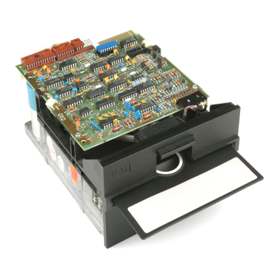
Tandon TM100-1 Manuals
Manuals and User Guides for Tandon TM100-1. We have
2
Tandon TM100-1 manuals available for free PDF download: Operating And Service Manual
Tandon TM100-1 Operating And Service Manual (115 pages)
Disk drives 48 tracks per inch
Brand:
Tandon
| Category:
Storage
| Size: 2.35 MB
Table of Contents
Table of Contents
3
Introduction
9
Purpose of the Disk Drive
9
Physical Description of the Disk Drive
9
Functional Description of the Disk Drive
9
Diskettes
10
Mechanical and Electrical Specifications
10
Interface Circuit Specifications
10
Uncrating the Disk Drive
10
Physical Checkout of the Disk Drive
12
Interface Connections
12
Chassis Ground
12
Isolated Ground
13
Mounting the Disk Drive
13
Hardware
13
TM-100 Disk Drive Mounting Configuration
13
Dust Cover
14
Cooling System Requirements
14
Diskette Care, Handling, and Storage
14
Write Protect
14
Operation of the Disk Drive
14
Organization of the Disk Drive
15
Components of the Disk Drive
15
Index Pulse
15
Write Protect
15
Track 00 Switch
15
Spindle Drive System
15
Positioner Control
16
Data Electronics
16
Disk Drive Functional Block Diagram
16
Data Recording
17
FM Recording Magnetization Profiles
17
Write Operation Timing Diagram
18
Interface Electronics
19
Interface Connector Pin Assignments, J1 /P1
19
Power Connector Pin Assignments
19
Option Select
19
Input Line Terminations
19
Read Timing Diagram
19
Drive Select
22
Power Save Option
22
Section II - Maintenance Checks and Adjustments
23
Introduction
23
Drive Motor Checks and Adjustments
23
Long-Term Drive Motor Speed Checks and Adjustment
23
Instantaneous Speed Variation Check
24
Bottom View of the TM-100 Disk Drive
24
Location of R4 Speed Control Pot
24
Cats Eye Alignment Check and Adjustment
25
CE Alignment Ctieck
25
ISV Pulse Pattern
25
Hub Center Line and Track Locations
26
Cats Eye Pattern
27
Head Adjustment
28
Track 00 Stop Adjustment
28
Head Module Retaining and Cam Screws
28
Track 00 Stop
29
Index Checks and Adjustment
30
Index Checks
30
Index-To-Data Pulse
30
Index Adjustment
31
Compliance Check and Adjustment
31
Compliance Check
31
Index Sensor's Retaining Screw and Adjustment
32
Compliance Adjustment
33
Upper Arm and Nuts
33
Write Protect Switch Adjustment Procedure
34
Write Protect Switch Adjustment
34
Printed Circuit Board Operation
35
Introduction
35
Explanation of Symbols and Abbreviations
35
Physical Description of the Logic PCBA
35
Interface Electronics Specifications
37
Interface Configuration
37
Input Control Lines
38
Drive Motor Enable (NMOTORON)
38
Side Select N SIDE SELECT)
38
Select Lines Schematic Diagram
39
Direction and Step Lines Schematic Diagram
43
Write Data Circuit Block Diagram
45
Write Data Schematic Diagram
46
Side Select Schematic Diagram
47
Outputs
48
Index (N INDEX/SECTOR)
48
Index Schematic Diagram
48
Waveform at Test Point 7 (Soft Sectored)
48
Track 00 (N TRK 00)
49
Write Protect (N WRITE PROTECT)
49
Track 00 Schematic Diagram
49
Read Data (N READ DATA)
50
Write Protect Schematic Diagram
50
Read Data Schematic Diagram
52
Read Circuit Block Diagram
53
Physical Description of the Servo PCBA
54
Input Control Lines
54
Troubleshooting Guide
56
Ntroduction
56
Will Not Write
57
Will Not Read
58
Front Panel LED Inoperative
58
Section V - Replacement Procedures
60
Introduction
60
Drive Belt
60
Logic PCBA
60
Servo PCBA
60
Drive Belt and Pulleys
61
Logic Printed Circuit Board Assembly
62
Logic PCBA Connectors and Mounting Screws
62
Cone Lever Assembly Harnessing and Mounting
65
Cone Lever Assembly Cable Harness
67
Cone's Component Parts
69
Activity LED Assembly Cable Harnessing
71
Activity LED Assembly Retaining Collar and LED Grommet
72
Activity LED Assembly Retaining Collar and Grommet
74
Front Panel Mounting Screws
74
Front Panel Bushings and Locating Tabs
76
Index Emitter Sensor Harnessing and Mounting
78
Index Detector Sensor Mounting Screw and Cable
79
Index Emitter and Index Detector Sensor Cables and Bundle
79
Drive Motor Assembly Harnessing and Mounting
81
Drive Motor Assembly Pulley
82
Track 00 Switch Assembly Cable Harnessing
83
Track 00 Switch Assembly E-Rings and Adjustment Screw
84
Track 00 Switch Assembly Mounting Screw
84
Write Protect Switch Assembly Arm and Adjustment Screw
86
Write Protect Switch Assembly Cable Harnessing
87
Upper Arm Assembly Parts
90
Felt Pad on Upper Arm
90
Module Assembly Parts
91
Spindle Assembly Retainer and Hex Head Screws
94
Latch Plate Assembly Mounting Screws and Latch Inhibitor
96
Advertisement
Tandon TM100-1 Operating And Service Manual (105 pages)
DISK DRIVES
Brand:
Tandon
| Category:
DC Drives
| Size: 5.16 MB
Table of Contents
Section 1
7
Table of Contents
7
Section 2
64
Drive Belt
65
Logic Circuit Board
65
Servo Circuit Board
67
Cone Lever Assembly
68
Activity L.E.D
71
Cone Assembly
71
Front Panel
74
Guide Rail
74
Index Assembly
75
Drive Motor Assembly
78
Drive Motor Harnessing and Mounting
79
Drive Motor Pulleys
80
Track 0 Switch Assembly
80
Track 0 Cable Harnessing
81
Track 0 Adjustment Screw
82
Write Protect Switch
83
Write Protect Cable Harness
84
Write Protect Mounting Adjustment Screw S
84
Head Module Assembly
85
Upper Arm Assembly
85
Upper Arm Screws
86
Felt Pad on Upper Arm
87
Latch Plate Assembly
89
Advertisement
Related Products
Tandon TM 100
Tandon TM100-2
Tandon TM100-2A
Tandon TM603SE
Tandon TM602S
Tandon TM848-2E
Tandon TM848-1E
Tandon TM362
Tandon TM262
Tandon TM603S
Tandon Categories
Storage
Floppy Disk Drive
DC Drives
More Tandon Manuals
Login
Sign In
OR
Sign in with Facebook
Sign in with Google
Upload manual
Upload from disk
Upload from URL