Table of Contents
Advertisement
Quick Links
Advertisement
Table of Contents

Related Manuals for ITT Goulds Pumps 3107


Summary of Contents for ITT Goulds Pumps 3107
- Page 1 Installation, Operation and Maintenance Instructions 3107...
-
Page 3: Table Of Contents
Table of Contents Table of Contents 1 Safety.................................. 3 1.1 Important Safety Notice..........................3 1.2 Safety warnings............................3 1.3 Safety ................................ 4 1.4 General precautions ..........................5 1.5 ATEX Considerations and Intended Use....................8 1.6 Parts ................................9 2 Installation................................ 10 2.1 Description of units.......................... - Page 4 Table of Contents 6 Maintenance..............................36 6.1 Lubrication............................... 36 6.2 Impeller adjustment ..........................37 6.3 Disassembly of pump ..........................37 6.4 Sectional View and Parts List........................41 6.5 Inspection and Overhaul ......................... 42 6.6 Reassembly of pump..........................42 7 Trouble check list ............................47 7.1 No liquid delivered...........................
-
Page 5: Safety
ITT Goulds pumps will provide safe, trouble-free service when properly installed, maintained, and operat- Safe installation, operation, and maintenance of ITT Goulds Pumps equipment are an essential end user responsibility. This Pump Safety Manual identifies specific safety risks that must be considered at all times during product life. -
Page 6: Safety
Trapped liquid can rapidly expand and result in a violent explosion and injury. ITT Goulds Pumps will not accept responsibility for physical injury, damage, or delays caused by a failure to observe the instructions for installation, operation, and maintenance contained in this Pump Safety Manual or the current IOM available at http://www.gouldspumps.com/literature. -
Page 7: General Precautions
Personal injuries will result if procedures outlined in this manual are not followed. ITT Goulds Pumps will not accept responsibility for physical injury, damage or delays caused by a failure to observe the instructions in this manual and the IOM provided with your equip- ment. - Page 8 Lift equipment only at specifically identified lifting points or as instructed in the current IOM. Current manuals are available at www.gouldspumps.com/literature_ioms.html or from your local ITT Goulds Pumps sales representative. Note: Lifting devices (eyebolts, slings, spreaders, etc.) must be rated, selected, and used for the entire load being lifted.
- Page 9 1.4 General precautions WARNING Make sure to properly lubricate the bearings. Failure to do so may result in ex- cess heat generation, sparks, and / or premature failure. CAUTION The mechanical seal used in an ATEX classified environment must be proper- ly certified.
-
Page 10: Atex Considerations And Intended Use
Maintenance manual (IOM) can cause serious personal injury or damage to the equipment. This in- cludes any modification to the equipment or use of parts not provided by ITT Goulds Pumps. If there is any question regarding the intended use of the equipment, please contact an ITT Goulds representative before proceeding. -
Page 11: Parts
The code classification marked on the equipment must be in accordance with the specified area where the equipment will be installed. If it is not, do not operate the equipment and contact your ITT Goulds Pumps sales representative before proceeding. -
Page 12: Installation
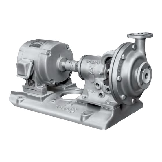
2 Installation 2 Installation 2.1 Description of units Reference is made to several different types of pumps in the following text. To enable the reader to asso- ciate these terms to his particular unit, photographs of typical units with an identifying description are shown below. -
Page 13: Location
2.3 Location 2.3 Location Pumping unit should be placed as close as practical to the source of supply. Floor space and head room allotted to the unit must be sufficient for inspection and maintenance. Be sure to allow for crane or hoist service. -
Page 14: Installation - Horizontal Pumps
2.5 Installation - horizontal pumps 2.5 Installation - horizontal pumps Bedplate mounted units are normally mounted on a concrete foundation of liberal thickness poured on a solid footing, using a one-three-five mix. The foundation should be substantial in order to absorb any vi- bration and to form a permanent, rigid support for the pumping unit. -
Page 15: Alignment Procedures
2.6 Alignment procedures Figure 5: By adjustment of wedges, bring the bedplate to an approximate level and provide the proper dis- tance above the foundation for grouting ( ¾" to 1½"). Level or plumb the suction and discharge flanges. Bring pump and motor shafts into reasonable alignment making absolutely certain that motor shaft is not above pump shaft or if it is, that there is a sufficient thickness of shims under the motor feet to allow for adjustment during alignment Tighten foundation bolts, but only finger tight. - Page 16 2.6 Alignment procedures NOTICE: Alignment in one direction may alter alignment in another. Check through each alignment pro- cedure after making any alignment alteration. Parallel alignment Unit is in parallel misalignment when the shaft axes are parallel but not concentric. Shift driver as re- quired.
- Page 17 2.6 Alignment procedures Figure 8: Casing mounted units Pumpage temperature Above ambient Motor Temperature Shaft Ambient .002" - .004" Low 100°F .000" - .002" High 200°F .004" - .006" High 300°F .008" - .010" High 400°F .012" - .014" High 500°F .016"...
- Page 18 2.6 Alignment procedures Figure 10: Dial indicator Angular alignment Unit is in angular misalignment when the shaft axes are concentric, but not parallel. Shim unit as re- quired. Flexible Couplings The normal gap (distance between coupling halves) is approximately 1/2". However, the coupling manufacturer's instructions should be followed.
-
Page 19: Piping - General
2.7 Piping - general Place a dial indicator on one shaft hub and rotate that hub 360°. Take readings from the face of the other hub. Alignment is achieved when indicator does not deflect more than .002". See Fig. Figure 13: Dial indicator 2.7 Piping - general All piping must be supported independently of the pump. -
Page 20: Piping - Suction
2.8 Piping - suction Figure 14: 2.8 Piping - suction General Properly installed suction piping is of extreme importance for trouble-free centrifugal pump operation. Use of elbows close to the pump suction flange should be avoided. Where used, elbows should be long radius. - Page 21 2.8 Piping - suction Figure 16: A centrifugal pump should never be throttled on the suction side. Suction strainers, when used, should have a net "free area" of at least three times the suction pipe area. Separate suction lines should be used when more than one pump is operating from the same source of supply.
-
Page 22: Piping - Discharge
2.9 Piping - discharge Figure 18: The velocity of the water approaching the pump suction pipe should be kept to a maximum of one foot per second to avoid air being drawn into the pump. Pump suction inlet velocities and submergence (the height of the water above the pump inlet) are two additional factors that must be considered. -
Page 23: Connection Of Piping
2.10 Connection of piping Increasers, if used in discharge line, should be placed between the pump and check valves. If quick-closing valves are installed in the system, cushioning devices should be used to protect the pump from surges and water hammer. 2.10 Connection of piping Connect suction and discharge piping to the pump. -
Page 24: Preparation For Operation
3 Preparation for operation 3 Preparation for operation 3.1 Pump bearings Oil lubrication Oil lubricated pumps are not lubricated at the factory. A high quality turbine type oil, with rust and oxidation inhibitors, should be used. Constant level oilers are supplied with most oil lubricated pumps. -
Page 25: Driver Bearings And Coupling
Driver bearings and coupling The pump steady bearings (below the pump support plate) are sleeve type and made of various materi- als depending upon the application of the pump. Refer to 6.1 Lubrication on page 36 for specific details. Close-coupled pumps Close-coupled pumps contain no pump bearings. - Page 26 3.3 Stuffing boxes Figure 21: To pack the stuffing box, install the packing and lantern ring in the proper sequence. Each ring should be installed separately. Firmly seat each ring. Use of a wooden split bushing is recommended. See Fig. 22. Use gland to jack the bushing and ring into the box.
-
Page 27: Connection Of Sealing Liquid Or Grease Lubricator (Packed Box)
3.4 Connection of sealing liquid or grease lubricator (packed box) CAUTION: Connection of sealing liquid or grease lubricator (packed box) If the stuffing box pressure is above atmospheric pressure, and the pumpage is clean, normal gland leak- age of 40 to 60 drops per minute is usually sufficient to lubricate and cool the packing and sealing liquid is not required. -
Page 28: Connection Of Drain Piping
3.6 Connection of drain piping Bearings Bearing cooling is available on some units. When it is available, cooling water must be connected to the jacket when pumping hot liquids. See the temperature limits listed under Construction Details in 6.4 Sec- tional View and Parts List on page 41. -
Page 29: Connection Of Equalizing Piping
3.7 Connection of equalizing piping 3.7 Connection of equalizing piping Some multi-stage pumps have equalizing piping to equalize pressure on the stuffing boxes (see 6.4 Sec- tional View and Parts List on page 41. This piping is in the box of fittings which accompanies the pump. The ends of the piping must be connected to the openings in each stuffing box. -
Page 30: Starting Pump
4 Starting pump 4 Starting pump 4.1 Checking for free turning Rotate shaft by hand to be sure rotating element is free. If element rubs or binds: Check alignment Pipe loads should be removed Check impeller clearance (if external adjustment is possible) as outlined in Impeller clearance ad- justment. - Page 31 4.3 Priming Close air vent valves, start pump and open discharge gate valve. Pump will continue to be primed for any future starting. This method is the simplest and, particularly for automatic operation, the safest. A float switch in the suc- tion reservoir can be arranged to stop pump, should there be failure of liquid supply.
- Page 32 4.3 Priming In either of these methods (1) and (2) , the pump will remain primed, provided foot valve is tight. Any failure, however, of foot valve when pump is standing idle, will permit the pump to lose its prime. During long idle periods, the pump can also lose its prime through leakage from stuffing boxes.
-
Page 33: Initial Inspection After Starting
4.4 Initial inspection after starting Figure 27: Priming by automatic primer pump Where there is a fluctuating suction lift that occasionally might drop below the normal limits of the pump, or for installations where there is any quantity of air entrained in the pumpage, the system shown in Fig. 28 is very well adapted. -
Page 34: Alignment - Final
4.5 Alignment - final Mechanical seal The mechanical seal was adjusted at the factory. If the seal leaks slightly when pump is first started, a few Some units do not require doweling since lock washers are furnished which hold the pump and driver feet securely in place. - Page 35 4.6 Doweling On units to be doweled (except those noted above), drill through two diagonally opposite feet of the pump into the bedplate. Use a reamer with a ¼" per foot taper. The dowels should extend well into the bedplate but project above the pump feet. Drivers should also be doweled but the driver manufacturer should be contacted for instructions.
-
Page 36: Operation
5 Operation 5 Operation 5.1 Stuffing box Stuffing boxes with packing rings - less quenching liquid or grease lubricator: Periodically inspect stuffing box to see that there is sufficient leakage to lubricate the packing and maintain a cool box. Never draw up packing so that the stuffing box heats, as this will cause damage to both packing and sleeve. -
Page 37: Operating At Reduced Head
5.3 Operating at reduced head also is insurance against damage due to running the pump against a closed discharge valve or very low flow conditions. Bearing temperature relay which will shut the unit down if the bearing temperature exceeds a predetermined maximum. -
Page 38: Maintenance
6 Maintenance 6 Maintenance 6.1 Lubrication Lubrication Oil Lubrication – (Refer to 3.1 Pump bearings on page 22 for oil specifications). Oil lubricated ball bearings are optional on the Model 3107. The Bearings are not lubricated at the factory. Remove adjustment assembly from oiler. Adjust bars to Dim. -
Page 39: Impeller Adjustment
6.2 Impeller adjustment 6.2 Impeller adjustment Some end suction pumps, in addition to vertical pumps, have means of adjusting impeller clearance with- in the casing. The clearance was set at the factory, but in transit, the clearance may have been lost. Proper clearance must be attained before a pump is operated or serious damage may occur. - Page 40 6.3 Disassembly of pump Figure 31: (a-1) Loosen set screws in deflector and drive collar and move rotary portion of seal back on shaft. (a-2) Remove gland bolts and slide gland toward bearing frame. (a-3) Remove impeller. Threads are right hand. Hold impeller by hand and use a strap or spanner wrench to unscrew shaft.
- Page 41 6.3 Disassembly of pump Figure 33: The rotary portion of the seal is fastened to the impeller hub by set screws. Loosen set screws by inserting a long Allen wrench into the tapped connection on the stuffing box. After loosening set screws, proceed as follows: (c-1) Loosen set screws in deflector and remove gland nuts.
- Page 42 6.3 Disassembly of pump Figure 34: 3107 Installation, Operation and Maintenance Instructions...
-
Page 43: Sectional View And Parts List
6.4 Sectional View and Parts List 6.4 Sectional View and Parts List Figure 35: Sectional view Table 3: Parts list Item No. No. reg. per Part Name Material pump Casing PTFE & ductile iron Impeller PTFE & ductile iron Bearing Housing Cast Iron Ball Brg.-Cpl. -
Page 44: Inspection And Overhaul
6.5 Inspection and Overhaul Item No. No. reg. per Part Name Material pump 351A Gasket-Discharge Flange (not illustrat- PTFE Envelope 351B Gasket-Suction Flange (not illustrated PTFE Envelope Retaining Ring - Shaft Steel 361A Retaining Ring - Bearing Housing Steel Mechanical Seal Non-metalic Table 4: Construction Details Pump Weight - Bare (lbs) - Page 45 6.6 Reassembly of pump Figure 36: Lubricate bearings seats on shaft and slide bearings on shaft as far as possible by hand. Use a driving sleeve such as the one shown in 8.5 Ball bearing installation on page 51. Make sure sleeve contacts inner race only.
- Page 46 6.6 Reassembly of pump Figure 37: (a-1) Place inner seal gasket, stationary seat, and outer seal gasket into stuffing box cover. (a-2) Bold stuffing box cover to frame. (a-3) Bolt gland to stuffing box cover. Tighten bolts evenly. (a-4) Screw impeller on shaft until impeller butts firmly against shaft shoulder. Care should be taken not to damage seal rotating assembly when installing impeller.
- Page 47 6.6 Reassembly of pump Figure 38: (b-1) Place deflector and rotary portion of seal on shaft. (b-2) Place inner seal gasket, stationary seat, and outer seal gasket in stuffing box cover. (b-3) Bolt gland to stuffing box cover. Be sure gaskets are in proper position and bolts are tightened evenly.
- Page 48 6.6 Reassembly of pump (c-1) Slide deflector (1A), gland (1-B), outboard stationary seat gaskets (1-C) on shaft. (c-2) Place inboard stationary seat (2A) and gaskets (2B) in stuffing box cover. (c-3) Slide impeller hub through stuffing box cover. (c-4) Slide rotary portion of seal on impeller hub. (c-5) Slide stuffing box over rotary portion of seal and firmly tighten nuts.
-
Page 49: Trouble Check List
7 Trouble check list 7 Trouble check list 7.1 No liquid delivered Pump not primed - casing and suction pipe not completely filled with liquid. Speed too low*. Discharge head too high. Check system head (particularly friction loss). Suction lift too high (suction pipe may be too small or long, causing excessive friction loss). Check with vacuum or compound gauge. -
Page 50: Pump Works A While And Then Quits
7.4 Pump works a while and then quits Air or gases in liquid. Impeller diameter may be too small. Mechanical defects: • Impeller clearance too great • Impeller damaged Wrong direction of rotation. Be sure pressure gauge is in correct place on discharge nozzle or discharge pipe. * When directly connected to electric motors, check whether motor wiring is correct and receives full volt- age. -
Page 51: Pump Is Noisy Or Vibrates
7.7 Pump is noisy or vibrates 7.7 Pump is noisy or vibrates Hydraulic noise - cavitation, suction lift too high. Check with vacuum or compound gauge. Mechanical defects: • Shaft bent • Rotating parts bind, are loose or broken • Bearings worn out •... -
Page 52: Care And Maintenance Of Bearings
8 Care and Maintenance of Bearings 8 Care and Maintenance of Bearings 8.1 Bearing temperatures All bearings operate at some temperature above that of the surrounding atmosphere, unless cooled. Heat is generated within the bearing due to rolling friction, churning of oil and the "drag" of the race. Do not use the human hand as a thermometer. -
Page 53: Bearing Removal
8.4 Bearing removal 8.4 Bearing removal Ball Bearings A puller such as the one shown in Fig. 40 should be used. The puller bar must be square with the end of the shaft at all times in order to keep even pressure on the outer circumference of the bearing. - Page 54 8.5 Ball bearing installation bearing must be kept square at all times. Once the bearing is located on the shaft, a driving sleeve, such as the one shown in Fig. 40 should be used. The sleeve should contact the inner race of the bearing only.
-
Page 55: Ordering Of Spare Parts
9 Ordering of spare parts 9 Ordering of spare parts 9.1 Spare parts To ensure against possible long and costly downtime periods, especially on critical services, it is advisa- ble to have spare parts on hand. The most desirable parts to have on hand are the following: Horizontally Split Case Pumps Rotating element. -
Page 56: Instructions For Ordering Spare Parts
9.2 Instructions for ordering spare parts Stuffing box packing (if any) - one set for each stuffing box. Stuffing box gland packing (if any) - one set. Shaft sleeve (if any). Ball bearings - one of each. Shaft nut (if any). Bearing locknut and washer ( if any). - Page 57 Visit our website for the latest version of this document and more information: www.gouldspumps.com ITT - Goulds Pumps Vertical Products Operation 3951 Capitol Avenue City of Industry, CA 90601-1734 Form IOM.3107.en-US.2021-09 ©2021 ITT Corporation The original instruction is in English. All non-English instructions are translations of the original instruction.
Need help?
Do you have a question about the Goulds Pumps 3107 and is the answer not in the manual?
Questions and answers