
Related Manuals for Agilent Technologies PL-GPC 220


Summary of Contents for Agilent Technologies PL-GPC 220
- Page 1 Agilent PL-GPC 220 Integrated HT-GPC/SEC System User Manual PL-GPC 220 User Manual Agilent Technologies...
- Page 2 Notices Warranty © Agilent Technologies, Inc. 2012 receive no greater than Restricted Rights as defined in FAR 52.227-19(c)(1-2) (June No part of this manual may be reproduced The material contained in this docu- 1987). U.S. Government users will receive in any form or by any means (including elec- ment is provided “as is,”...
- Page 3 This chapter provides information on environmental requirements, physical and performance specifications. 3 Unpacking the Instrument This chapter gives information on how to unpack your PL-GPC 220. 4 Using the Module This chapter provides information on how to set up the instrument for an analysis and explains the basic settings.
- Page 4 In This Guide... 8 Parts for Maintenance This chapter provides information on parts for maintenance. 9 Appendix This chapter provides addition information on safety, legal and web. PL-GPC 220 User Manual...
-
Page 5: Table Of Contents
Performance Specifications 3 Unpacking the Instrument Unpacking the Instrument 4 Using the Module The Graphical User Interface Setting Up the PL-GPC 220 Running Samples on the PL-GPC 220 5 Troubleshooting and Diagnostics Diagnostics General Troubleshooting Guide 6 Error Information Errors... - Page 6 Back Pressure Regulator (BPR) Differential Refractive Index Detector Autosampler 8 Parts for Maintenance Parts List Pump Spares 9 Appendix General Safety Information The Waste Electrical and Electronic Equipment Directive Radio Interference Sound Emission Agilent Technologies on Internet PL-GPC 220 User Manual...
- Page 7 PL-GPC 220 User Manual Introduction to PL-GPC 220 Introduction System Description and General Operation Instrument Overview Solvent Module Column Oven PL-GPC 220 Autosampler Injection Sequence This chapter gives an instrument overview and an introduction to the function of the PL-GPC 220.
-
Page 8: Introduction
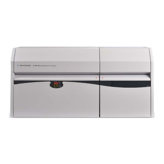
Introduction to PL-GPC 220 Introduction Introduction The Agilent PL-GPC 220 Integrated HT GPC/SEC System is a fully automated chromatograph designed specifically for Gel Permeation Chromatography (GPC) / Size Exclusion Chromatography (SEC). The instrument features a 40-position carousel, high sensitivity refractive index detector and a reliable isocratic solvent delivery system housed uniquely in a temperature controlled enclosure. -
Page 9: Introduction To Pl-Gpc
Introduction to PL-GPC 220 System Description and General Operation System Description and General Operation Instrument Overview Figure 2 Overview (modules) Control drawer Autosampler Main oven module Solvent delivery module Pump Solvent degasser PL-GPC 220 User Manual... - Page 10 Introduction to PL-GPC 220 System Description and General Operation Figure 3 Overview (display and control elements) Power switches Oven over-temperature display and control Autosampler over-temperature display and control Temperature and RI display Oven and laser safety interlock switches Status indicator...
- Page 11 Introduction to PL-GPC 220 System Description and General Operation Solvent Module Figure 4 PL-GPC 220 Solvent Module The top section of the solvent module is temperature controlled to 32 °C, preventing solvents such as 1,2,4–trichlorobenzene and dimethyl sulfoxide freezing should the laboratory temperature fall below 15 °C. The warm air from the top solvent section is then circulated across the pump head and degasser and ventilated from the rear of the unit.
- Page 12 Introduction to PL-GPC 220 System Description and General Operation Figure 5 Stainless steel tank All the optional vessels are fitted with float switch, which trigger an audible alarm should the eluent container run too low or the waste container get too full.
- Page 13 Introduction to PL-GPC 220 System Description and General Operation Column Oven Figure 6 Standard Oven Configuration Oven Fan with Heaters Temperature Sensors Differential Refractive Index Detector Sample Needle Assembly Column Mounts Injection Valve Vapour Sensor PL-GPC 220 User Manual...
- Page 14 Introduction to PL-GPC 220 System Description and General Operation The low split line of the oven allows easy access to the oven facilitating column exchange and routine maintenance. The temperature within the oven is controlled by eight active heaters; 3 are built into the base of the oven and 4 in the oven lid, the eighth heater is mounted directly in front of the fan and it is this heater that provides the fine control.
- Page 15 Introduction to PL-GPC 220 System Description and General Operation PL-GPC 220 Autosampler The carousel will accommodate 40 x 2 mL sample vials, 39 of these (positions 1 to 39 ) are used for sample injection. The 40 th or zero vial is dedicated as the “index”...
- Page 16 Introduction to PL-GPC 220 System Description and General Operation Figure 8 Temperature controlled zones in the carousel PL-GPC 220 User Manual...
- Page 17 Introduction to PL-GPC 220 System Description and General Operation Injection Sequence 1 Default condition prior to injection: Injection valve in the Inject position • Vial in carousel • Syringe at mid point • 2 Sample loaded Valve switched to load position •...
- Page 18 Introduction to PL-GPC 220 System Description and General Operation 3 Sample injected Sample injected • Excess sample from overflow loop returned to the vial • Vial returned to the carousel • PL-GPC 220 User Manual...
-
Page 19: Site Requirements And Specifications
PL-GPC 220 User Manual Site Requirements and Specifications Site Requirements Physical Specifications Performance Specifications This chapter provides information on environmental requirements, physical and performance specifications. Agilent Technologies... -
Page 20: Site Requirements
In case of emergency it must be possible to disconnect the instrument from the power line at any time. ➔ Make sure the power connector of the instrument can be easily reached and unplugged. ➔ Provide sufficient space behind the power socket of the instrument to unplug the cable. PL-GPC 220 User Manual... - Page 21 Never operate your instrumentation from a power outlet that has no ground connection. ➔ Never use a power cord other than the Agilent Technologies power cord designed for your region. Use of unsupplied cables WA R N I N G Using cables not supplied by Agilent Technologies can lead to damage of the electronic components or personal injury.
- Page 22 N O T E aware of overhead obstructions. If a G7821A PL-GPC 220 Viscometer or G7822A PL-GPC 220 Dual angle LSD is supplied with the instrument, allow an additional 30 cm (12 in) for each of these detector control systems on the width of the bench space.
-
Page 23: Physical Specifications
Site Requirements and Specifications Physical Specifications Physical Specifications Table 1 Physical Specifications PL-GPC 220 Type Specification Comments Line voltage 230 V AC (±10 %) Single phase with earth Power consumption 3300 VA, 2310 W/7900 BTU Line frequency 50 or 60 Hz (±5 %) Size (width ×... -
Page 24: Performance Specifications
Site Requirements and Specifications Performance Specifications Performance Specifications Table 2 Performance Specifications of the PL-GPC 220 Unit Type Specification Pump Flow Range 0.2 – 10 mL/min Pump 0.1 – 5.0 mL/min software controlled ≤0.07 % RSD, or ≤0.02 min SD... -
Page 25: Unpacking The Instrument
PL-GPC 220 User Manual Unpacking the Instrument Unpacking the Instrument This chapter gives information on how to unpack your PL-GPC 220. Agilent Technologies... -
Page 26: Unpacking The Instrument
Unpacking the Instrument Damaged Packaging If the delivery packaging shows signs of external damage, please call your Agilent Technologies sales and service office immediately. Inform your service representative that the instrument may have been damaged during shipment. "Defective on arrival" problems C A U T I O N If there are signs of damage, please do not attempt to install the module. - Page 27 3 Remove the five sections of foam packaging surrounding the unit: one at each side, one piece at the front and two small sections behind the unit. The wires are tucked down between the two foam sections at the back. PL-GPC 220 User Manual...
- Page 28 7 Open the outer and inner oven lids, the solvent module lid and the solvent module front flap to let condensation evaporate. 8 Remove the foam packaging which surrounds the pump located in the base compartment of the solvent delivery module prior to operation. PL-GPC 220 User Manual...
-
Page 29: Using The Module
Time Estimator System Monitor Data Acquisition Setting Up the PL-GPC 220 Starting the Instrument Introducing Solvent to the PL-GPC 220 Running the PL-GPC 220 Changing Columns Changing Solvents in the PL-GPC 220 Changing the Injection Loop Running Samples on the PL-GPC 220... -
Page 30: The Graphical User Interface
The Graphical User Interface A Windows-based Graphical User Interface (GUI) providing total instrument control is used to operate the PL-GPC 220. An intuitive single control panel provides simplistic control as well as a comprehensive monitoring system. The instrument status can be rapidly assessed for each of the instrument’s modules. - Page 31 For each of the controlled modules, the key information is displayed together with a statement of current activity. Consult the online help in the PL GPC 220 Control software for more details about the various data- and event-logging options available. PL-GPC 220 User Manual...
-
Page 32: The Toolbar
Using the Module The Graphical User Interface The Toolbar The Toolbar contains the following icons: PL-GPC 220 User Manual... -
Page 33: Modes Of Operation
• STANDBY – indicated by a RED LED on both the interface and the instrument display panel is the boot-up mode, in which all modules are off. This is the mode of operation the PL-GPC 220 is set for routine maintenance, such as solvent or column exchange or in any circumstance when the oven needs to be opened. -
Page 34: Autosampler
Configuring the Controlled Modules - Configuration Editors To change any of the set conditions, simply click on the coloured section of the instrument graphic to open the configuration editor for that module. PL-GPC 220 User Manual... - Page 35 The programmed minimum and maximum pressure settings enable pressure limits within which the pump can operate. If the recorded pump pressure (system pressure) falls outside these limits, the instrument will default to error conditions. Oven Configuration Editor PL-GPC 220 User Manual...
- Page 36 Using the Module The Graphical User Interface The PL-GPC 220 oven can be controlled at two temperatures: • one programmed for the Idle mode and • one for the Run mode. Typically, these temperatures would be set at the same temperature, but if it...
- Page 37 Limits value is used as the baseline stabilization threshold, and the system will continue cycling between purging, zeroing and monitoring until the baseline drift is less than the programmed limits measured over a 10 min period. PL-GPC 220 User Manual...
- Page 38 • Wait Until Stable – If this box is checked, the system will wait until the oven temperature is stable (non-flashing green LED) before performing sample injection. • First Vial – Position in the carousel of the first vial in the autosampler sequence. PL-GPC 220 User Manual...
- Page 39 • Sample Run Time – The duration time of the sample run. Using 30 cm PLgel columns at 1.0 mL/min, the following sample run times are recommended (if a PL-GPC 220 Viscometer is installed in parallel, then the times shown in parentheses should be used to allow the viscometer break through peak to elute before the injection of the next sample): 1 column –...
-
Page 40: Methods
To use any of the stored methods, select it and once it is displayed in the editor click on the Send button. The instrument parameters displayed in the editor will only be downloaded to the PL-GPC 220 when the Send button has been pressed. The Defaults button restores the default conditions to the screen from which you may wish to start your custom method. -
Page 41: Security
Access to the dialog shown below is password protected with an option to change the password. The default password is POLYMER220 and this is case insensitive. Entering the correct password results in the following dialogue: PL-GPC 220 User Manual... -
Page 42: Changing The Password
The change password dialog is shown below: If one forgets the password, the PL-GPC 220 Control will accept the default password once the GPC220.pwd file is deleted from the install directory. -
Page 43: Time Estimator
Time Estimator dialog displayed. This dialog will remain on the screen until the A/S sequence starts or until the Cancel button is pressed. PL-GPC 220 User Manual... -
Page 44: System Monitor
While the system is running, it is often preferential to display the data acquisition on the computer screen rather than the instrument control. The System Monitor minimizes the PL-GPC 220 Control to an informative icon, displaying the important parameters. Data Acquisition The Data Acquisition option enables one to program a link from the PL-GPC 220 Control to another program of choice. -
Page 45: Setting Up The Pl-Gpc 220
When the inialization process has completed, the instrument should be left in the STANDBY (red light) mode with the pump and heaters off. 4 Launch the PL-GPC 220 Control software from the control PC. 5 Replace the columns by a barrel connector. - Page 46 Using the Module Setting Up the PL-GPC 220 6 Flush the entire system with the solvent required. See “Introducing Solvent to the PL-GPC 220” on page 47. When changing between two immiscible solvents, intermediary solvent(s) should be used N O T E that are fully miscible with the chromatography solvents used.
-
Page 47: Introducing Solvent To The Pl-Gpc 220
Using the Module Setting Up the PL-GPC 220 Introducing Solvent to the PL-GPC 220 Preparations Instrument is running. 1 Place the solvent line fitted with sinter into the solvent reservoir. 2 Open the purge valve on the front of the pump (turn counter-clockwise) and allow the solvent to flow from the pump purge valve into the waste container. - Page 48 Setting Up the PL-GPC 220 9 If a viscometer is fitted, additional flushing of the viscometer pressure transducers is required - see the G7821A PL-GPC 220 Viscometer manual. 10 Once the system is totally flushed into the desired chromatography solvent: a Turn off the pump.
-
Page 49: Running The Pl-Gpc 220
If the columns are not already in the solvent that is to be used as eluent they need to be N O T E transferred as indicated by the manufacturer. This can be performed in the PL-GPC 220, but do not flush the columns through the detectors, simply flush the columns directly to waste. -
Page 50: Changing Columns
Using the Module Setting Up the PL-GPC 220 Changing Columns Preparations System is in RUN mode. 1 Change the Idle and Low flow rates to 0.2 mL/min and the Idle temperature to 40 °C. 2 Put the instrument into IDLE mode and allow the oven cool. -
Page 51: Changing Solvents In The Pl-Gpc 220
Using the Module Setting Up the PL-GPC 220 Changing Solvents in the PL-GPC 220 Preparations System is in RUN mode. 1 Change the Idle and Low flow rates to 0.2 mL/min and the Idle temperature to 40 °C. 2 Put the instrument into IDLE mode and let the oven cool. -
Page 52: Changing The Injection Loop
Using the Module Setting Up the PL-GPC 220 Changing the Injection Loop Preparations The column is in RUN mode. 1 Change the Idle and Low flow rates to 0.2 mL/min and the Idle temperature to 40 °C. 2 Put the instrument into IDLE mode and let the oven cool. -
Page 53: Running Samples On The Pl-Gpc 220
Using the Module Running Samples on the PL-GPC 220 Running Samples on the PL-GPC 220 Setting up the Autosampler Sequence Preparations • Start the log file to monitor the condition of the instrument during operation. • Ensure that there is sufficient eluent to carry out the analysis (you can use the time estimator tool on the Control software once you have defined the autosampler sequence). -
Page 54: Loading The Samples
Using the Module Running Samples on the PL-GPC 220 Loading the Samples Preparations • Start the log file to monitor the condition of the instrument during operation. • Ensure that there is sufficient eluent to carry out the analysis (you can use the time estimator tool on the Control software once you have defined the autosampler sequence). -
Page 55: Troubleshooting And Diagnostics
PL-GPC 220 User Manual Troubleshooting and Diagnostics Diagnostics General Troubleshooting Guide Boot Up Problems Autosampler Problems RI Problems Oven Temperature Control Problems Solvent Module Problems Pump Problems Chromatography Problems This chapter gives an overview about the troubleshooting and diagnostic features. -
Page 56: Diagnostics
Tools/Utility menu. The diagnostic utility consists of three tabbed views: • AS General Status displays the autosampler status Figure 12 Autosampler General Status • AS Temperatures displays the autosampler temperatures Figure 13 Autosampler Temperatures PL-GPC 220 User Manual... - Page 57 Troubleshooting and Diagnostics Diagnostics • Other Modules Status displays the other instrument functions Figure 14 Other Module Status PL-GPC 220 User Manual...
-
Page 58: General Troubleshooting Guide
Check the pump serial link is connected correctly to both the rear of the • pump and the back of the PL-GPC 220 Control drawer. • Injection valve failure Check that the Link cables on the rear of the Control drawer are •... -
Page 59: Autosampler Problems
Check the purge column is not blocked (if fitted), by observing a • significant decrease in system pressure when the purge valve opens. • Low sensitivity Clean the RI cell thoroughly (for example sonicate in 10 % nitric acid). • PL-GPC 220 User Manual... -
Page 60: Oven Temperature Control Problems
Pump Problems • High back pressure generated at pump Replace the purge frit • • Low flow rate Purge pump to remove air bubbles • Please contact your local Agilent service representative to check the • valves PL-GPC 220 User Manual... -
Page 61: Chromatography Problems
Check that the autosampler syringe plunger seal is gas-tight. • Check that the syringe Luer adaptor not leaking. • • Long retention times Check the pump flow rate. • Check for a leak on the Purge valve. • PL-GPC 220 User Manual... - Page 62 Troubleshooting and Diagnostics General Troubleshooting Guide • Mirrored peaks Ensure that the purge valve is closed. • Inspect the RI cell for cracks, particularly in partition. • PL-GPC 220 User Manual...
-
Page 63: Error Information
PL-GPC 220 User Manual Error Information Errors This chapter describes the meaning of error messages, and provides information on probable causes and suggested actions how to recover from error conditions. Agilent Technologies... -
Page 64: Errors
Figure 15 Error Handling Dialog When an error occurs, pressing the help button on the error dialog will open the help file at the troubleshooting section giving further instructions on how to overcome the error reported. PL-GPC 220 User Manual... - Page 65 Temp = 0 °C or - (-, -) Flash STBY " sensor is not > 999.99 °C responding correctly" SENSOR "The vapour Open/Short 5 s (5 s) Flash STBY " sensor is not circuit responding correctly" PL-GPC 220 User Manual...
- Page 66 Flash carousel after during being closed" autosampler LOAD "Failed to switch cmd failed - (-, 3) Flash valve to load response from position" autosampler "Failed to switch " - (-, 3) Flash valve to inject position" PL-GPC 220 User Manual...
- Page 67 (variable, Flash success response Solvent SOLVENT LEVEL "Solvent level low I/O state - (-, -) Flash or waste level change high" SOLV VAP "Vapor sensor " - (-, -) Flash and/or over-temp error" PL-GPC 220 User Manual...
- Page 68 Error Information Errors PL-GPC 220 User Manual...
-
Page 69: Maintenance
Flush the DRI Cell with a Cleaning Agent Autosampler Lubricate Autosampler Syringe (not applicable to serial controlled A/S systems) Cleaning the Condensing Chamber Autosampler Track Lubrication Autosampler Needle Removal, Cleaning and Replacement This chapter provides general information on maintenance of the PL-GPC 220. Agilent Technologies... -
Page 70: Introduction
For your convencience an annual inspection is offered as part of our preventative service contract. Please contact your local office or agent for information about purchasing the preventive service option. PL-GPC 220 User Manual... -
Page 71: Warnings And Cautions
Make sure that only fuses with the required rated current and of the specified type (super-fast, fast, time delay etc) are used for replacement. ➔ The use of repaired fuses and the short-circuiting of fuse-holders must be avoided. PL-GPC 220 User Manual... - Page 72 C A U T I O N ➔ If you connect external equipment to the instrument, make sure that you only use accessory units tested and approved according to the safety standards appropriate for the type of external equipment. PL-GPC 220 User Manual...
-
Page 73: Cleaning
1 Moisten a soft cloth with diluted detergent solution. 2 Wipe down the exterior of the instrument. 3 Moisten a soft cloth with deionized water. 4 Wipe down the exterior of the instrument. 5 Allow the instrument to dry off completely before reconnecting power. PL-GPC 220 User Manual... -
Page 74: Decontamination
2 Identify and, if possible, correct the source of the leak. 3 Inspect cabling, parts and surfaces to determine whether or not any damage has occurred. 4 Allow the the instrument to dry completely before reconnecting power. 5 Dispose of contaminated waste appropriately. PL-GPC 220 User Manual... -
Page 75: Testing Overtemperature Protection Systems
42 °C. The overtemperature protection systems for following modules should be tested regularly: • Oven • Autosampler • Solvent module PL-GPC 220 User Manual... -
Page 76: Oven Overtemperature Protection Test
3 Once oven cooling has been verified, adjust the over temperature display to 5 °C above the oven set point and press the reset button to silence the alarm. This concludes the oven over temperature protection system test. PL-GPC 220 User Manual... -
Page 77: Autosampler Overtemperature Protection Test
50 °C. This test can be carried out at higher temperatures but the warm and hot zones must both be at the same temperature, between 50 °C and 130 °C, before commencing the test. The PL-GPC 220 must be in RUN mode for this test. Remove all sample vials except Vial 0 if necessary. - Page 78 Once hot zone cooling has been verified then adjust the over temperature display to 4 – 6 °C above the present hot zone set point and press the reset button to silence the alarm. This concludes the autosampler over temperature protection system test. PL-GPC 220 User Manual...
-
Page 79: Solvent Module Overtemperature Protection Test
It may be necessary to remove solvent and waste bottles from the solvent module compartment to clear enough space. Switch ON the PL-GPC 220 oven unit and solvent module Slacken off the two screws, which fix the compartment and set the instrument to IDLE. - Page 80 After a few seconds the solvent module alarm buzzer will sound and an error notification will be displayed on the PL-GPC 220 Control software. Next Steps: Leave the probe in the hot water for a few minutes and check the temperature of the heat sink again. This should now be noticeably cooler.
-
Page 81: Testing Vapor Sensors
Maintenance Testing Vapor Sensors Testing Vapor Sensors The vapor sensors are tested by simulating a solvent leak or spillage in the following modules: • Oven • Solvent module PL-GPC 220 User Manual... -
Page 82: Solvent Module Vapor Sensor Test
Acetone Syringe Preparations Switch ON the PL-GPC 220 if necessary and set it to IDLE mode with the oven temperature set to 40 °C. 1 Ensure that the front flap on the solvent module is closed. 2 Place the paper on the floor of the solvent compartment (see Figure page 82). - Page 83 6 Remove the paper ball from the solvent module and dispose of it appropriately. 7 Close the front flap again and wait a minute or so until the solvent module alarm ceases. 8 Clear the error on the Control software This concludes the solvent module vapour sensor test. PL-GPC 220 User Manual...
-
Page 84: Oven Vapor Sensor Test
Syringe Preparations Switch ON the PL-GPC 220 if necessary and set it to IDLE mode with the oven temperature set to 40 °C. 1 Heat the oven to 40 °C in IDLE or RUN mode with a pump flow rate of 0.5 mL/min. - Page 85 10 Open the oven and remove the paper. Dispose of it appropriately. 11 Leave the oven open for one minute to allow the acetone vapour to disperse. 12 Close both oven lids. 13 Clear the error on the Control software This concludes the oven vapour sensor test. PL-GPC 220 User Manual...
-
Page 86: Testing Solvent Level Sensors
Testing Solvent Level Sensors Testing Solvent Level Sensors If your PL-GPC 220 solvent module is fitted with steel solvent tanks a pair of liquid level sensing float switches will have been provided. These can be tested after removing them from the tanks and laying them on the floor of the solvent compartment. - Page 87 Department for assistance. Liquid level alarms are of a purely advisory nature and are not essential to the safe operation of the instrument. Replace solvent tanks and float switches to resume normal operation of the PL-GPC 220. PL-GPC 220 User Manual...
-
Page 88: Testing Oven Door Interlock
If the alarm condition does not occur then switch off and disconnect the power cords from N O T E both units. Contact your local Agilent Service Department for assistance. This concludes the oven door interlock test. PL-GPC 220 User Manual... -
Page 89: Laser Interlock Switch
(when installed) when the oven door is opened. 1 Check the connection of cable from the safety interlock switch to the interlock connection at the rear of the light scattering control box. PL-GPC 220 User Manual... -
Page 90: Degasser Test
The dissolved gas is removed from the solvent through a membrane (thin wall PTFE tubing) inside a vacuum chamber. See the Agilent 1260 Infinity Quaternary Pump manual for further information. PL-GPC 220 User Manual... -
Page 91: Back Pressure Regulator (Bpr)
BPR and at all times should be less than the NORMAL operating pressure. Figure 16 Purge Valve Purge Mode and Solvent Flow 1 Turn off the solvent flow. 2 Locate the BPR at the back of the solvent delivery module and remove it. PL-GPC 220 User Manual... - Page 92 3 Fit the replacement BPR with the arrow in the direction of the flow, for example from right to left. 4 Turn on the flow and open the PURGE valve. Check the system backpressure and check for leaks at the joints disturbed. PL-GPC 220 User Manual...
-
Page 93: Differential Refractive Index Detector
1 Purging the DRI Cell 2 Flushing the DRI Cell with a Cleaning Agent 3 Removal of the Cell and Replacement of Seals PL-GPC 220 User Manual... -
Page 94: Purge The Dri Cell
5 Press the Purge button to close the purge valve. 6 Allow the system adequate time to settle after the purge. For high temperature applications, this settling time can be up to 8 hours. PL-GPC 220 User Manual... -
Page 95: Flush The Dri Cell With A Cleaning Agent
3 Switch on the pump and set the flow rate at 1.0 mL/min. Alternatively both sides of the cell could be continually flushed by changing the plumbing from the conventional arrangement (Figure 17 on page 96) to sample and reference in series (Figure 18 on page 96). PL-GPC 220 User Manual... - Page 96 Maintenance Differential Refractive Index Detector Figure 17 Conventional Plumbing Figure 18 Sample and Reference in Series for Continuous Flushing PL-GPC 220 User Manual...
-
Page 97: Autosampler
Maintenance Autosampler Autosampler To ensure optimum performance of the autosampler system, it is recommended that the following important maintenance procedures be performed every 3 – 6 months depending on instrument usage. PL-GPC 220 User Manual... -
Page 98: Lubricate Autosampler Syringe (Not Applicable To Serial Controlled A/S Systems)
5 Work the plunger up and down the barrel a few times to thoroughly disperse the oil. 6 Reconnect the syringe to the tubing and relocate in the mounting. 7 Return the A/S drawer to its normal operating position. PL-GPC 220 User Manual... -
Page 99: Cleaning The Condensing Chamber
Figure 19 Plumbing diagram 1 Remove the left hand side panel from the PL-GPC 220 main unit: a Lift the top section of the panel front and up and disconnect the earth cable from the panel. -
Page 100: Autosampler Track Lubrication
2 With a piece of tissue paper moistened with acetone, wipe clean the entire track that the vial holders sit on. 3 Using a cotton bud (Q-tip®) sprinkle a small amount of graphite powder over the track. 4 Replace the carousel and return the drawer to its operating position. PL-GPC 220 User Manual... -
Page 101: Autosampler Needle Removal, Cleaning And Replacement
A hollow shaft 1/4 in nut spinner is preferable but not essential to remove and replace the needle 2 mm Allen key wrench Allen wrench extender handle 1 Switch the PL-GPC 220 system off and remove the mains lead from the back of the unit. 2 Open the oven compartment lid and locate the Autosampler needle assembly, positioned between the RI block and the Valco valve head assembly. - Page 102 Maintenance Autosampler 10 Holding the needle assembly firmly in position, tighten the two M3 stainless steel socket cap screws. 11 Reconnect the capillary tubing. 12 Reconnect the power lead(s) and the switch instrument ON. PL-GPC 220 User Manual...
-
Page 103: Parts For Maintenance
PL-GPC 220 User Manual Parts for Maintenance Parts List Pump Spares This chapter provides information on parts for maintenance. Agilent Technologies... -
Page 104: Parts List
Parts for Maintenance Parts List Parts List Description PL0870-6110 Solvent reservoir filter PL0800-0003 Injection valve rotor seal PL1-23926 Vial locator solenoid and plunger assembly PL4-32434 Replacement Inline filter cartridges PL0810-0012 Autosampler needle (pk 2) PL-GPC 220 User Manual... -
Page 105: Pump Spares
Standard seals (pack of 2) 5001-3707 Gold seal, outlet 5062-8562 Active Inlet Valve Cartridge (400 bar) 5001-3708 AIV gold washer 01018-21207 AIV plastiv cap 5062-2485 (2x) Cap (pack of 4) 1 x pump outlet valve, 1 x pump purge valve PL-GPC 220 User Manual... - Page 106 Parts for Maintenance Pump Spares PL-GPC 220 User Manual...
-
Page 107: Appendix
PL-GPC 220 User Manual Appendix General Safety Information Safety Symbols General Safety Information Safety Standards Operation Precautions The Waste Electrical and Electronic Equipment Directive Radio Interference Sound Emission Agilent Technologies on Internet This chapter provides addition information on safety, legal and web. -
Page 108: General Safety Information
C A U T I O N alerts you to situations that could cause loss of data, or damage of equipment. ➔ Do not proceed beyond a caution until you have fully understood and met the indicated conditions. PL-GPC 220 User Manual... -
Page 109: General Safety Information
Make sure that only fuses with the required rated current and of the specified type (normal blow, time delay, and so on) are used for replacement. The use of repaired fuses and the short-circuiting of fuse holders must be avoided. PL-GPC 220 User Manual... - Page 110 When working with solvents, observe appropriate safety procedures (for example, goggles, safety gloves and protective clothing) as described in the material handling and safety data sheet by the solvent vendor, especially when toxic or hazardous solvents are used. PL-GPC 220 User Manual...
-
Page 111: Precautions
(up to 220 °C). ➔ Handle these components carefully. ➔ Wear suitable protective gloves. Vapor sensors are used in both modules of the PL-GPC 220 to alert the operator to solvent leaks. PL-GPC 220 User Manual... - Page 112 C A U T I O N The surge safe device causes the instrument to fail the insulation resistance test of the standard portable appliance test (PAT Test). ➔ Unplug the surge safe device before the PAT test is performed. PL-GPC 220 User Manual...
-
Page 113: The Waste Electrical And Electronic Equipment Directive
With reference to the equipment types in the WEEE Directive Annex I, this product is classed as a Monitoring and Control Instrumentation product. Do not dispose off in domestic household waste N O T E To return unwanted products, contact your local Agilent office, or see www.agilent.com more information. PL-GPC 220 User Manual... -
Page 114: Radio Interference
Appendix Radio Interference Radio Interference Cables supplied by Agilent Technologies are screened to provide optimized protection against radio interference. All cables are in compliance with safety or EMC regulations. Test and Measurement If test and measurement equipment is operated with unscreened cables, or... -
Page 115: Sound Emission
This product has a sound pressure emission (at the operator position) < 70 dB. • Sound Pressure Lp < 70 dB (A) • At Operator Position • Normal Operation • According to ISO 7779:1988/EN 27779/1991 (Type Test) PL-GPC 220 User Manual... -
Page 116: Agilent Technologies On Internet
Appendix Agilent Technologies on Internet Agilent Technologies on Internet For the latest information on products and services visit our worldwide web site on the Internet at: http://www.agilent.com Select Products/Chemical Analysis PL-GPC 220 User Manual... - Page 117 PL-GPC 220 User Manual...
- Page 118 Index unpacking vapor sensor test solvent module waste electrical and electronic equipment WEEE directive PL-GPC 220 User Manual...
- Page 120 In This Book This manual contains information on the Agilent PL-GPC 220 Integrated HT-GPC/SEC System (G7820A) The manual describes the following: • General information, • Introduction • Site requirements • Unpacking • Using the module • Troubleshooting and diagnostics •...