Table of Contents
Advertisement
Available languages
Available languages
Quick Links
Advertisement
Chapters
Table of Contents

Related Manuals for KNOVA KN 8056


Summary of Contents for KNOVA KN 8056
- Page 1 Digital automotive multimeter Multímetro digital automotriz KN 8056...
-
Page 2: Table Of Contents
Alligator Clip 1 piece 9V Battery (NEDA1604, 6F22 or 1 piece In 1999 counts and 3-1/2 digits, the KN 8056 is a 0006P) manual testing automotive digital Multimeter. Spotting a unique design with an extra large In the event you find any missing or damage, screen, this meter has useful features such as a please contact your dealer immediately. -
Page 3: Safety Information
Safety information CAT.II: Local level, appliance, PORTABLE • Soft cloth and mild detergent should be used to EQUIPMENT etc., with smaller transient clean the surface of the multimeter when overvoltages than CAT. III servicing. No abrasive and solvent should be used to prevent the surface of the multimeter CAT III: Distribution level, fixed installation, with from corrosion, damage and accident. -
Page 4: International Electrical Symbols
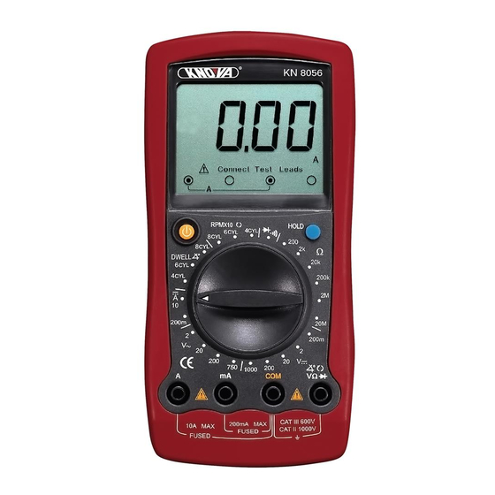
Automotive Servicing Safety Guide All the information, explanations and detailed The Multimeter Structure (see figure 1) descriptions in the operation manual have originated from the industrial information recently published. It is impossible to prove the accuracy and completeness of the information, of which we shall not be responsible for the assumption. -
Page 5: Measurement Operation
Display Symbols The DC voltage ranges are: 200.0mV, 2.000V, Symbol Meaning 20.00V, 200.0V and 1000V. The battery is low. The AC voltage ranges are: 2.000V, 20.00V, Warning: To avoid false 200.0V and 750V readings, which could lead to possible electric shock or personal To measure DC or AC voltage, connect injury, replace the battery as soon the multimeter as follows:... -
Page 6: Resistance Testing
Multimeter Basic Testing The measurement ranges of DC current are: 2. Set the rotary switch to an appropriate 200.0mA and 10.00A. measurement position in Ω range. To measure current, do the following: 3. Connect the test leads across with the object being measured. -
Page 7: Continuity Testing
Multimeter Basic Testing To test a diode out of a circuit, connect F. Dwell Testing (see figure 7) the multimeter as follows: figure 7 Ignition 1. Insert the red test lead into the terminal coil and the black test lead into the COM terminal. 2. -
Page 8: Data Holding
Multimeter Basic Testing 1. Set the rotary switch to RPMx10. less than 10Ω, indicating that the fuse is good. When the display is overload “1”, it is shown 2. As prompted at the LCD connect terminal, that the fuse has been blown out. insert the red test lead into the terminal and the black one into the COM terminal. -
Page 9: Starting/Charging System Testing
Diagnosis of automotive Troubles 12.60 V 100% Voltage Temperature 9.6 V or more 21.1º C (70º F) 12.45 V 9.5 V 15.6º C (60º F) 12.30 V 9.4 V 10.0º C (50º F) 12.15 V 9.3 V 4.4º C (40º F) E. -
Page 10: Charging System Voltage Testing
Diagnosis of automotive Troubles Secondary H. Charging System Voltage Testing Coil This testing is used to see if the charging system operates normally so as to provide the electronic Black systems with adequate power (lamps, electric fans, radio sets, etc.). 1. -
Page 11: Hall Switch/Sensor Testing
Diagnosis of automotive Troubles (3) Connect the red and black test lead probes in The functions of a magnetic resistance sensor is parallel to the two ends of the high-voltage similar to those of a Hall sensor and the testing damper and observe the reading. -
Page 12: Engine Sensor Testing
Diagnosis of automotive Troubles A. Start the engine of the automobile to achieve a Testing Procedure: rotation speed of 3000 RPM. So far as a GM (1) Move the oxygen sensor out of the automobile. automobile is concerned, set the rotary switch to the DWELL and select 6CYL. -
Page 13: Position Sensor
The sensor converts the air flow into a DC voltage, The MAP sensor is used to change a pressure low frequency or high frequency signal. KN 8056 signal into a DC voltage or frequency one. All GM, can only be used to test a DC voltage or low Chrysler, Honda and Toyota use DC voltage type frequency signal. -
Page 14: General Specifications
Diagnosis of automotive Troubles figure 20 • Fuse Protection of 10A terminal : CE Version: 10A, 250V, fast type, ø5 x 20mm • Measurement Speed : Updates 2-3 Ground times /second. • Maximum Display : 1999. • Temperature : Operating: 0ºC~40ºC (32ºF~104ºF) Storage: -10ºC~50ºC Black... -
Page 15: Ac Voltage
Accurate Specifications B. AC Voltage G. Dwell Testing Range Resolution Accuracy Overload protection Range Resolution Accuracy Overload protection 4CYL 10mV ±(0.8%+5) 1000 VDC or 750 6CYL 0.1º ±(3%+5) 600 VP VAC continuous 200V 100mV 8CYL 750V ±(1.0%+4) Remark: Remark: Input Amplitude: More than or equal to 10 V in direct impulse;... -
Page 16: Replacing The Battery
Maintenance WARNING C. Replacing the Battery (see figure 22) To avoid electrical shock or arc blast, or Open Up Screw personal injury or damage to the Meter, use specified fuses ONLY in accordance with the following procedure. Battery To replace the Meter’s fuse: 1. -
Page 17: Información General
Batería de 9V (NEDA1604, 6F22 o 0006P) 1 pieza El KN 8056 es un multímetro digital para pruebas (instalada dentro del multímetro) manuales automotrices. Diseño único con pantalla En caso de encontrar piezas faltantes o dañadas, extra grande, este multímetro tiene características... -
Page 18: Reglas De Seguridad
Información de seguridad CAT III: Nivel de distribución, instalación fija, con • Debe utilizarse un paño y detergente suave sobretensiones transitorias más pequeñas que CAT. IV. para limpiar la superficie del multímetro cuando se realice el mantenimiento. No deben utilizarse Utilice el multímetro sólo como se especifica en este sustancias abrasivas ni solventes para evitar manual, de lo contrario la protección proporcionada... -
Page 19: Símbolos Eléctricos Internacionales
Información de seguridad porque dichos componentes operan con altas 1. ¿El automóvil ha sido reparado recientemente? tensiones cuando el automóvil está en ¿El mismo problema ha ocurrido varias veces funcionamiento. en el ese lugar? • Para conectar o cortar un componente 2. -
Page 20: Símbolos En Pantalla
Símbolos en pantalla Símbolos en pantalla (ver figura 2) Operación de medición Prueba básica del multímetro A. Medición de tensión de CD/CA (ver Figura 3) figura 2 Símbolo Significado Batería descargada. Advertencia: Para evitar lecturas falsas, que podrían conducir a posibles descargas eléctricas o lesiones físicas, cambie la batería tan pronto como se visualice este indicador. -
Page 21: B Medición De Corriente Cd
Operación de medición B. Medición de corriente CD (ver Figura 4) C. Prueba de resistencia (ver Figura 5) figura 5 figure 4 ADVERTENCIA Para evitar daños al multímetro o en los dispositivos sometidos a prueba, desconecte la alimentación del circuito y descargue todos ADVERTENCIA los capacitores de alto voltaje antes de medir la Nunca intente realizar una medición de... -
Page 22: Prueba De Diodo
Operación de medición D. Prueba de diodo (ver Figura 6) • La unidad de diodo es voltios (V), mostrando el valor positivo de caída de tensión de conexión. • Cuando se complete la medición de diodos, desconecte la conexión entre las puntas de prueba y el circuito bajo prueba. -
Page 23: Tacómetro Del Motor (Velocidad De Rotación) "Rpmx10
Operación de medición (Por ejem.: Un carburador de retroalimentación • Si un sistema de encendido con un tablero de GM). distribuidor se usa en el automóvil, conecte el sensor de la punta de prueba roja al extremo 1. Ajuste el selector giratorio en DWELL. negativo primario de la bobina de encendido. -
Page 24: Prueba De Interruptor: Cheque El
Diagnóstico de problemas automotrices B. Prueba de interruptor: Cheque el interruptor 2. Los resultados de las pruebas se muestran a para ver si funciona correctamente. continuación y si la batería tiene una carga inferior a 100 %, por favor, utilícela después 1. -
Page 25: Prueba De Caída De Tensión
Diagnóstico de problemas automotrices 3. Interrumpa el sistema de encendido para Circuito de tensión de disparo típico de pérdida. desactivar el arranque del automóvil. Corte la Solenoide bobina de encendido principal; la bobina de derivación, la cámara y el sensor de arranque con el fin de interrumpir el sistema de encendido. -
Page 26: Prueba Del Sistema De Encendido
Diagnóstico de problemas automotrices I. Prueba del sistema de encendido 2. Pruebas del sistema de encendido de alto voltaje (ver Figura 11) 1. Prueba de la bobina de encendido Negro (1) Antes de la operación, enfríe el motor y apague Rojo la bobina de encendido. -
Page 27: Prueba De Resistencia Magnética
Diagnóstico de problemas automotrices (2) Como se indica en la pantalla LCD, conectar (2) Conecte el polo positivo de la batería de 9 V la terminal, inserte la punta de prueba roja en al extremo de la fuente del sensor y el polo la terminal y la punta de prueba negra en el negativo al extremo de tierra del sensor con... -
Page 28: Prueba Del Sensor Del Motor
Diagnóstico de problemas automotrices (2) Prueba de resistencia del inyector de Procedimiento de prueba: combustible (ver Figura 15) (1) Retire el sensor de oxígeno del automóvil. Injector de (2) Ajuste el interruptor giratorio a 200Ω. Como combustible se indica en la pantalla LCD conectar la terminal, inserte el cable de prueba rojo en la Rojo terminal Ω... -
Page 29: Sensor De Temperatura
Diagnóstico de problemas automotrices 2. Sensor de temperatura (ver Figura 17) (2) Conecte los sensores de las puntas de prueba roja y negra respectivamente a la terminal de El sensor de temperatura cambia la resistencia prueba de señales y a la terminal conectado de salida a través de los cambios en las a tierra. -
Page 30: Flujo De Masa De Aire (Maf)
El sensor convierte el flujo de aire en una señal de tensión de CD, de baja frecuencia o alta fre- • Frecuencia = R.P.M./30. (Esto sólo se aplica cuencia. El KN 8056 sólo puede ser utilizado para a 4CYL.) probar una tensión DC o señal de baja frecuencia. -
Page 31: Especificaciones De Precisión
Especificaciones generales • Deficiencia de C. Corriente CD la batería: Pantalla Rango Resolución Precisión Protección de sobrecarga • Lectura negativa: Pantalla CE: Fusible 315 mA, 250 V 200mA 0.1mA ±(0.8%+5) tipo rápido, ø5 x 20 mm • Sobrecarga: Pantalla 1. CE: Fusible 10A, 250 V •... -
Page 32: Prueba De Tacómetro (Velocidad De Rotación)
Especificaciones generales H. Prueba de tacómetro (velocidad de rotación) Para reemplazar el fusible del multímetro: Rango Resolución Precisión Protección de sobrecarga 1. Apague el multímetro y retire todas las conexiones de las terminales. 4CYL 2. Retire la funda del multímetro. 6CYL 10 RPM ±(3%+5) - Page 33 Notes / Notas...
- Page 34 www.knova.com.mx...
Need help?
Do you have a question about the KN 8056 and is the answer not in the manual?
Questions and answers