Table of Contents
Advertisement
Available languages
Available languages
Quick Links
Advertisement
Chapters
Table of Contents

Related Manuals for KNOVA KN 8058


Summary of Contents for KNOVA KN 8058
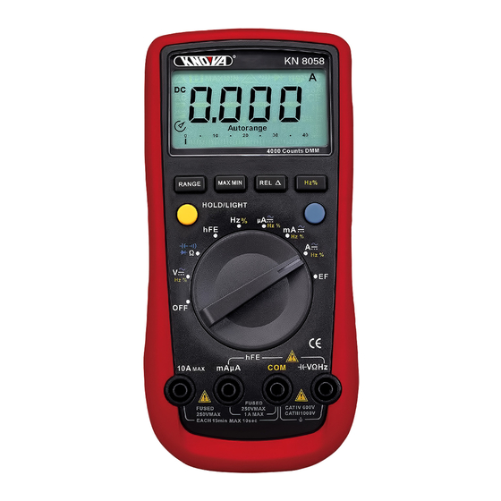
- Page 1 Digital professional multimeter Multímetro digital profesional KN 8058...
-
Page 2: Table Of Contents
CAT. IV. operation” carefully before using the meter. CAT IV: Primary supply level, overhead lines, cable Digital multimeter KN 8058 is an auto ranging systems etc. multimeter. the enclosure structure design adopted advanced “co-injection” tecchnique in Use the meter only as specified in this operating order to provide sufficient insulation. -
Page 3: International Electrical Symbols
Rules for Safe Operation • Before using the Meter inspect the case. Do not International Electrical Symbols use the Meter if it is damaged or the case (or part of the case) is removed. Look for cracks or AC or DC Grounding missing plastic. -
Page 4: Display Symbols
Display Symbols Symbol Meaning Symbol Meaning Data hold is active. The REL is on to display the stored value minus the present value. Sleep Mode indicator Ω: Ohm. The unit of resistance. Indicates negative reading. Ω, kΩ, kΩ: kilohm. 1 x 10³ or 1000 ohms. Indicator for AC measurement M Ω... -
Page 5: Measuring Resistance
Measurement Operation When the testing leads are connected to the current C. Measuring Resistance (See figure 4) terminals, do not parallel them across any circuit. To measure current, do the following: 1. Insert the red test lead into the μmA or A input terminal and the black test lead into the COM Select terminal. -
Page 6: Testing For Continuity
Measurement Operation • The LCD displays OL indicating open-circuit for the tested resistor or the resistor value is higher than the maximum range of the meter. • When resistance measurement has been Select completed, disconnect the connection between the testing leads and the circuit under test, and remove the testing leads away from the input terminals of the meter. -
Page 7: Frequency Measurement
Measurement Operation WARNING To measure frequency, connect the meter as follows: To avoid damage to the Meter or to the equipment under test, disconnect circuit power 1. Insert the red test lead into the COM terminal. and discharge all high-voltage capacitors before 2. -
Page 8: Operation Of Hold Mode
Measurement Operation 2. Place the housing front part with marking The BLUE botton towards the object being measured. It uses for selecting the required measurement func- 3. There will be three types of displays: tion when there is more than one function at one LCD displays different size of digits to position of the rotary switch. -
Page 9: Accuracy Specifications
General Specifications D. AC Current • Weight: Approximate 370 g (battery included). Range Resolution Accuracy Overload protection • Safety/Compliances: IEC61010 CAT.III 1000V, CAT.IV 600V over voltage and double insulacion 45Hz ~ 400Hz standard. 400μA 0.1μA Fuse 1: (1.2%+5) • Certifications: F1A H 240V (CE), 4000μA 1μA... -
Page 10: Diode Test
Accuracy Specifications H. Diode test Make sure the test leads are disconnected from the circuit being tested before opening the case Resolution Remarks Overload protection bottom. 0.001V Open circuit 1000Vdc / 750Vac To replace the battery: (See figure 11) voltage around 2.8V 1. -
Page 11: Información General
CAT IV. funcionamiento” antes de usar el multímetro. CAT IV: Nivel primario de suministro, líneas El multímetro digital KN 8058 es un multímetro suplementarias, sistemas de cable. con ajuste automático. El diseño de la estructura de la carcasa ha adoptado la técnica avanzada Utilice el multímetro sólo como se especifica en este... -
Page 12: Símbolos Eléctricos Internacionales
Reglas de seguridad • Antes de usar el multímetro inspeccione el estuche. Símbolos eléctricos internacionales No utilice el multímetro si está dañado o fuera del estuche (o parte del estuche) está removido. CD o CA Puesta a tierra Busque grietas o plásticos faltantes. Preste atención Doble aislamiento Deficiencia de al aislamiento alrededor de los conectores. -
Page 13: Símbolos En Pantalla
Símbolos en pantalla Símbolo Significado Símbolo Significado Retención de datos activada. El REL muestra el valor almacenado menos el valor actual. Indicador de modo de suspensión. Ω: Ohm. La unidad de resistencia. Indica lectura negativa. Ω, kΩ, kΩ: kilohm. 1 x 10³ o 1000 ohms. Indicador para medición de CA. -
Page 14: Medición De Resistencia
Operación de medición Cuando las puntas de prueba están conectadas a las C. Medición de resistencia (ver Figura 4) terminales de corriente, no se deben colocar en paralelo en ningún circuito. Para medir la corriente, se debe hacer lo siguiente: 1. -
Page 15: Prueba De Continuidad
Operación de medición • Si la pantalla muestra OL indica circuito abierto para el resistor a prueba o que el valor del resistor es mayor que el rango máximo del multímetro. Selector • Al finalizar la medición de resistencia, desconecte la conexión entre las puntas de prueba y el circuito bajo prueba, y desconecte las puntas de prueba de las terminales de entrada del multímetro. -
Page 16: Medición De Frecuencia
Operación de medición Para medir la frecuencia, conecte el multímetro ADVERTENCIA como se indica a continuación: Para evitar daños en el multímetro o en los equipos sometidos a prueba, desconecte la 1. Inserte la punta de prueba roja en la terminal Hz alimentación del circuito y descargue todos los y la punta de prueba negra en la terminal COM. -
Page 17: Operación De Modo De Retención
Operación de medición 2. Coloque la parte delantera de la carcasa con El botón AZUL la marca hacia el objeto que se está midiendo. Se utiliza para seleccionar la función de medición 3. Habrá tres tipos de pantallas: requerida cuando hay más de una función en una posición del selector giratorio. -
Page 18: Especificaciones De Precisión
Especificaciones generales • Bajo la influencia del fenómeno de campos D. Corriente CA electromagnéticos de radiofrecuencia radiados, Rango Resolución Precisión Protección de el modelo mencionado tiene un error de medición, sobrecarga 45Hz ~ 400Hz y regresa al estado normal cuando se elimina la interferencia. -
Page 19: Prueba De Diodo
Especificaciones de precisión H. Prueba de diodo Asegúrese de que las puntas de prueba están desconectadas del circuito sometido a prueba Resolución Observ. Protección de sobrecarga antes de abrir la carcasa inferior. 0.001V Tensión de 1000Vcd / 750Vca Cómo remplazar la batería: (ver Figura 11) circuito abierto aprox. - Page 20 www.knova.com.mx...
Need help?
Do you have a question about the KN 8058 and is the answer not in the manual?
Questions and answers