Table of Contents
Advertisement
Quick Links
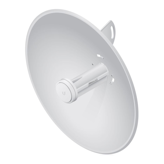
Package Contents
Reflector
Mounting Bracket
Flange Nuts (Qty. 2)
* The PBE-M5-400 Antenna Feed has a thin gray ring around the center of the cap to differentiate it
from the PBE-M5-300 Antenna Feed.
Installation Requirements
13 mm wrench
Shielded Category 5 (or above) cabling should be used for all wired Ethernet
connections and should be grounded through the AC ground of the PoE.
We recommend that you protect your networks from harmful outdoor environments and
destructive ESD events with industrial-grade, shielded Ethernet cable from Ubiquiti. For
more details, visit
ui.com/toughcable
Hardware Overview
PBE-M5-400 Quick Start Guide
Antenna Feed*
Pole Clamp
Gigabit PoE (24V, 0.5A) with
Mounting Bracket
Rear Housing
U-Bolt
Power Cord
Advertisement
Table of Contents

Related Manuals for Ubiquiti PBE-M5-400


Summary of Contents for Ubiquiti PBE-M5-400
- Page 1 Flange Nuts (Qty. 2) Gigabit PoE (24V, 0.5A) with Power Cord Mounting Bracket * The PBE-M5-400 Antenna Feed has a thin gray ring around the center of the cap to differentiate it from the PBE-M5-300 Antenna Feed. Installation Requirements 13 mm wrench Shielded Category 5 (or above) cabling should be used for all wired Ethernet connections and should be grounded through the AC ground of the PoE.
-
Page 2: Application Examples
PBE-M5-400 Quick Start Guide Ethernet This Gigabit Ethernet port is used to connect the power and should be connected to the LAN and DHCP server. Reset Button To reset to factory defaults, press and hold the Reset button for more than 10 seconds while the device is powered on. -
Page 3: Installation
PBE-M5-400 Quick Start Guide Installation... - Page 4 PBE-M5-400 Quick Start Guide...
- Page 5 PBE-M5-400 Quick Start Guide Optional (radome not included)
-
Page 6: Connecting Power
PBE-M5-400 Quick Start Guide Connecting Power WARNING: The switch port must comply with the power specifications listed in this Quick Start Guide. Optional Accessing airOS... -
Page 7: Installer Compliance Responsibility
The airOS Configuration Interface will appear, allowing you to customize your settings as needed. For details, refer to the User Guide available at ui.com/download/airmax You can also manage your device using the Ubiquiti® Network Management System. Setup using the UNMS™ app requires the U-Installer, sold separately. Installer Compliance Responsibility Devices must be professionally installed and it is the professional installer’s... -
Page 8: Specifications
This radio transmitter FCC ID: SWX-PBE5M / IC: 6545A-PBE5M has been approved by PBE-M5-400 Quick Start Guide FCC / ISED Canada to operate with the antenna types listed below with the maximum permissible gain for each antenna type indicated. Antenna types not included in this list or having a gain greater than the maximum gain indicated for that type, are strictly prohibited for use with this device. -
Page 9: Limited Warranty
1. Compliance is required with respect to voltage, frequency, and current requirements indicated PBE-M5-400 Quick Start Guide on the manufacturer’s label. Connection to a different power source than those specified may result in improper operation, damage to the equipment or pose a fire hazard if the limitations are not followed. -
Page 10: Declaration Of Conformity
This equipment complies with radiation exposure limits set forth for an uncontrolled PBE-M5-400 Quick Start Guide environment. This equipment should be installed and operated with minimum distance 20 cm between the radiator and your body. This transmitter must not be co-located or operating in conjunction with any other antenna or transmitter. - Page 11 PBE-M5-400 Quick Start Guide © 2021 Ubiquiti Inc. All rights reserved.
Need help?
Do you have a question about the PBE-M5-400 and is the answer not in the manual?
Questions and answers