
Related Manuals for Caple CM209WH


Summary of Contents for Caple CM209WH
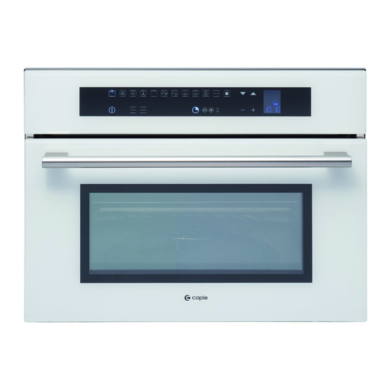
- Page 1 CM209WH Caple Built In Combi MW/Grill 460mm Caple Built In Combi MW/Grill 460mm Technical information...
- Page 2 Caple CM209 (SS & WH) combination microwave Features Stainless steel or white glass Stainless steel, black-spot feature bar handle Stainless steel interior Internal halogen light 11 Functions: • light • fan heat • grill & fan heat • full grill •...
- Page 5 CM209WH - Caple built in microwave Item Part Code Description 42703120 MUFFLE 12381850 MUFFLE GASKET (until 23/03/14) 12382130 MUFFLE GASKET (from 24/03/14) 12111260 BACK SHIELD 12111170 TOP SHIELD 12111860 AIR CONVEYOR F45N µONDE 12381530 FIBERGLASS SHELL 12380980 FIBERGLASS REAR 12530000...
- Page 6 CM209WH - Caple built in microwave Item Part Code Description 11380640 CAST IRON RUBBER GRILL 12541100 SAFETY THERMOSTAT T120¢C MAGNETRON 12112490 EXTERNAL BOTTOM 12111850 BOTTOM PROTECTION 12112480 COMPONENT SUPPORT 12192440 AIR CONVEYOR F45N MAGNETRON 12193250 INNER DOOR HANDLE PROFILE 12380920...
- Page 7 CM209WH Caple built in Microwave/Grill Service Manual...
-
Page 8: Table Of Contents
Microwave Oven Service Manual Models CM109-CM209 This document has been published to be used for service only. The contents are subject to change without notice CONTENTS 1. SERVICING REQUIREMENTS HEALTH & SAFETY 1.1.1 Electrical Safety 1.1.2 Good Working Practices 1.1.3 Insulation Test 1.1.4 Sheet Metal Edges 1.1.5 Microwave emissions MEASUREMENT OF ENERGY EMISSION... - Page 9 4. TROUBLE SHOOTING GUIDE ERROR MESSAGE MICROWAVE OVEN DOESN’T WORK COOLING FAN PROBLEMS CONVECTION FAN PROBLEMS OVEN LIGHT PROBLEMS DISPLAY PROBLEMS DOOR HINGES PROBLEMS BAD COOKING PERFORMANCE 7. COMPONENT REPLACEMENT AND ADJUSTMENT PROCEDURE MICROWAVE OVEN REMOVAL COOLING FAN MOTOR SUBSTITUTION OVEN DOOR REMOVAL CONVECTION FAN MOTOR SUBSTITUTION RING ELEMENT SUBSTITUTION...
-
Page 10: Servicing Requirements
Servicing Requirements Health & Safety Note: When servicing the oven, health and safety issues must be considered at all times. Specific safety issues are listed below with their appropriate icon. These are illustrated throughout the service information to remind service people of the health and safety issues 1.1.1 Electrical Safety WARNING! TO AVOID ELECTRIC SHOCK! -
Page 11: Measurement Of Energy Emission
Servicing Requirements Measurement of energy emission CAUTION For microwave energy emission On every service call. A check for microwave energy emission must be made according to the following manner. 1.2.1 Measurement of energy emission Measurement must be made with the microwave oven operating at its maximum output and containing a load of 275±15 milliliters of tap water initially at 20°±5°... -
Page 12: Special Tools & Materials
Servicing Requirements Special Tools & Materials 1.3.1 Tools 1.3.2 Necessary Measuring Instruments 7.5V Power Screw / Nut Driver Recommended TESTER (VOLTS-DC, AC, Ohmmeter) 3” socket extension bar Microwave survey meter 7mm socket Glass thermometer: 100°C or 212°F (1 deg scale) 10 mm socket 12mm socket Flexible shaft socket extension... -
Page 13: Technical Overview
Technical Overview Microwave oven Specifications 2.1.1 Oven Weight lbs /Kg =86/39 2.1.2 Power rating TECHNICAL DATA Electrical Ratings and Maximum Connected Load MICROWAVE OVENS @ 220-240 Volts 50Hz Amperes Watts CM109 – CM209 13.9 3200 2450... -
Page 14: Serial Plate
Technical Overview Serial Plate 2.2.1 Location The product serial number plate is located on the bottom profile trim. 2.2.2 Model & Serial Number The numbers printed on the plate contains the following information: Model Serial Number Electrical ratings... -
Page 15: Component Specifications
Technical Overview Components Specifications 2.3.1 Heating Elements Volts Freq. Watts Note Grill 1500 Ring (if present) 1500 2.3.2 Motors Volts Freq. Watts Note Convection Fan CL H 220-240 50/60 Cooling Fan CL H 220-240 50/60 Rotating Plate 2.3.3 Electric Components Volts Watts Note... - Page 16 Technical Overview System Description ELECTRONIC CONTROL. The control consists of a main power board and Full Touch Keyboard. COOKING MODE & TEMPERATURE SELECTION. The Microwave oven is full touch control for the set cooking modes and set temperature. TEMPERATURE SENSOR. There is one NTC sensor, fixed on the top of the internal cavity. MAGNETRON.
- Page 17 Technical Overview Test procedure Microwave Control IMPORTANT: The MANUAL TEST procedure can be activated only after power on. To enter in the MANUAL TEST follow the following procedure: a) NEW CONTROL BOARD (unprogrammed): When the oven is plugged in to the power the language mode appears to the display Holding simultaneously the &...
- Page 18 Hold key Grill: preset MAX; Verify the power of ring element (1500W); The following icons have to be turned on “cooking time” , “end cooking time” , bell , and & 6. During the microwave cooking functions the following parameters should be showed: Hold key the display shows “00:00”;...
- Page 19 Technical Overview Fault Numbers Faults N° Temperature sensor disconnected or shorted. Err 1 Door micro switch open Err 2 Electronic boards over temperature (more than 85°C) Err 3 Electronic boards sensor temperature damaged Err 4 Flexible key board damaged Err 5...
- Page 20 Technical Overview Oven Safety Features 2.7.1 Interlock Mechanism The door lock mechanism is a device which has been specially designed to eliminate completely microwave activity when the door is opened during cooking and thus to prevent the danger resulting from the microwave leakage. 2.7.2 Safety Thermostats This appliance is built with three bi-metal mechanical thermostats.
- Page 21 Troubleshooting guide Error Message NOTE: A MICROWAVE ENERGY LEAKAGE TEST MUST ALWAYS BE PERFORMED WHEN THE UNIT IS SERVICED FOR ANY REASON. BEFORE TOUCHING any parts of the oven, always remove the power plug from the outlet. For about 60 seconds after the oven stops, an electric charge remains in the high voltage capacitor. When replacing or checking, you must wait to permit the capacitor discarding.
- Page 22 Troubleshooting guide Microwave oven doesn’t work NOTE: A MICROWAVE ENERGY LEAKAGE TEST MUST ALWAYS BE PERFORMED WHEN THE UNIT IS SERVICED FOR ANY REASON. BEFORE TOUCHING any parts of the oven, always remove the power plug from the outlet. For about 60 seconds after the oven stops, an electric charge remains in the high voltage capacitor. When replacing or checking, you must wait to permit the capacitor discarding.
- Page 23 High voltage Transformer is Measure the resistance Normal readings: damaged (Wire leads removed): a. Approx. 2 ohm. With an ohm-meter on R x1 scale. b. Approx. 170 ohms. a. Primary winding; b. Secondary winding; 7.12 Measure the resistance Normal readings: (Wire leads removed): a.
- Page 24 resistance in both direction. Measure the continuity (Wire leads removed): Forward (Ohm-meter scale: Rx10000) Normal readings: Infinite. 7.16 Abnormal reading: continuity. Measure the continuity (Wire leads removed): Reverse (Ohm-meter scale: Rx10000) Safety Thermostat damaged Check for continuity of the thermostat’s contact with an Ohm-meter (Wire leads removed) 7.11...
- Page 25 Troubleshooting guide Cooling Fan Problems NOTE: A MICROWAVE ENERGY LEAKAGE TEST MUST ALWAYS BE PERFORMED WHEN THE UNIT IS SERVICED FOR ANY REASON. BEFORE TOUCHING any parts of the oven, always remove the power plug from the outlet. For about 60 seconds after the oven stops, an electric charge remains in the high voltage capacitor. When replacing or checking, you must wait to permit the capacitor discarding.
- Page 26 Troubleshooting guide Convection Fan Problems NOTE: A MICROWAVE ENERGY LEAKAGE TEST MUST ALWAYS BE PERFORMED WHEN THE UNIT IS SERVICED FOR ANY REASON. BEFORE TOUCHING any parts of the oven, always remove the power plug from the outlet. For about 60 seconds after the oven stops, an electric charge remains in the high voltage capacitor. When replacing or checking, you must wait to permit the capacitor discarding.
- Page 27 Troubleshooting guide Oven Light Problems NOTE: A MICROWAVE ENERGY LEAKAGE TEST MUST ALWAYS BE PERFORMED WHEN THE UNIT IS SERVICED FOR ANY REASON. BEFORE TOUCHING any parts of the oven, always remove the power plug from the outlet. For about 60 seconds after the oven stops, an electric charge remains in the high voltage capacitor. When replacing or checking, you must wait to permit the capacitor discarding.
- Page 28 Troubleshooting guide Display Problems NOTE: A MICROWAVE ENERGY LEAKAGE TEST MUST ALWAYS BE PERFORMED WHEN THE UNIT IS SERVICED FOR ANY REASON. BEFORE TOUCHING any parts of the oven, always remove the power plug from the outlet. For about 60 seconds after the oven stops, an electric charge remains in the high voltage capacitor. When replacing or checking, you must wait to permit the capacitor discarding.
- Page 29 Troubleshooting guide Door Hinge Problems NOTE: A MICROWAVE ENERGY LEAKAGE TEST MUST ALWAYS BE PERFORMED WHEN THE UNIT IS SERVICED FOR ANY REASON. BEFORE TOUCHING any parts of the oven, always remove the power plug from the outlet. For about 60 seconds after the oven stops, an electric charge remains in the high voltage capacitor. When replacing or checking, you must wait to permit the capacitor discarding.
- Page 30 Troubleshooting guide Bad Cooking Performance NOTE: A MICROWAVE ENERGY LEAKAGE TEST MUST ALWAYS BE PERFORMED WHEN THE UNIT IS SERVICED FOR ANY REASON. BEFORE TOUCHING any parts of the oven, always remove the power plug from the outlet. For about 60 seconds after the oven stops, an electric charge remains in the high voltage capacitor. When replacing or checking, you must wait to permit the capacitor discarding.
- Page 31 Component replacement and adjustment procedure Oven removal Disconnect the power supply cord. Open the door. Remove the screws shown in the pictures. Pull off the oven. Remove the oven by using the lateral handles. Lateral Handles (if present)
- Page 32 Component replacement and adjustment procedure Cooling fan motor substitution Disconnect the power supply cord and remove the Oven from the cabinet. Remove the upper cover. Disconnect the terminals on the fan. Remove the five screws on the fan and remove the fan.
- Page 33 User Manual Oven Door Removal To Remove Door To Replace Door Open the door completely. Insert the upper arms (2) of both hinges into the slots. The recesses (3) must hook on the lips (4). Lift up the hinge bracket (1) from the arms (2) . Move the hinge brackets (1) back down into position.
- Page 34 Component replacement and adjustment procedure Convection fan motor substitution Disconnect the power supply cord and remove the Oven from the cabinet. Remove the upper, rear and lateral covers. Disassemble the brackets by removing their three screws each (fig.1). Remove the back support by removing the last two screws on the top (fig.1).
- Page 35 Component replacement and adjustment procedure Ring element substitution Disconnect the power supply cord and remove the Oven from the cabinet. Remove the upper, rear and lateral covers. Disassemble the brackets by removing their three screws each (fig.1). Remove the back support by removing the last two screws on the top (fig.1).
- Page 36 Component replacement and adjustment procedure Grill element substitution Disconnect the power supply cord and remove the Oven from the cabinet. Remove the upper cover. Remove the internal component cover (fig 1) by its six screws. Remove the probe from its location using a clamp make rounded the border to extract it.(fig.2).
- Page 37 Component replacement and adjustment procedure Rotating Dish Motor Substitution Disconnect the power supply cord and remove the Oven from the cabinet. Open the door and remove the plastic insert (fig1). Put the oven with the door on a horizontal surface with a soft cloth to prevent scratching of the aesthetics.
- Page 38 Component replacement and adjustment procedure Magnetron Substitution Disconnect the power supply cord and remove the Oven from the cabinet. Remove the upper cover. Remove the internal component cover (fig 1) by its six screws. Remove the cooling channel (fig 2) by its two screws.
- Page 39 Component replacement and adjustment procedure Lock door switch substitution Disconnect the power supply cord and remove the Oven from the cabinet. Remove the upper, rear and lateral cover . Disconnect the terminals of micro switch. Remove the plastic support performing the two movements as showed in the figure.
- Page 40 Component replacement and adjustment procedure 7.10 Door Gasket substitution Open door and pull out the gasket by hands unhooking it by its 4 hooks on the corners. THE GASKET IS MADE BY A SPACIAL MATERIAL FOR MICROWAVE AND IT MUST BE FITTED PROPERLY. Replace with a new one by reversing the previous steps.
- Page 41 Component replacement and adjustment procedure 7.11 Safety thermostats substitution Disconnect the power supply cord and remove the Oven from the cabinet. Remove the upper cover. Remove the internal components cover (fig 1) by its six screws. Unscrew and disconnect the thermostat damaged (fig.2).
- Page 42 Component replacement and adjustment procedure 7.12 Transformer substitution Disconnect the power supply cord and remove the Oven from the cabinet. Remove the upper cover. Remove the internal components cover (fig 1) its six screws. Disconnect the cable of transformer damaged and unscrew it by 4 base screws.
- Page 43 Component replacement and adjustment procedure 7.13 Condenser substitution Disconnect the power supply cord and remove the Oven from the cabinet. Remove the upper cover. Remove the internal components cover (fig 1) its six screws. Disconnect the cable of condenser damaged and unscrew it by 2 base screws.
- Page 44 Component replacement and adjustment procedure 7.14 Probe Temperature substitution Disconnect the power supply cord and remove the Oven from the cabinet. Remove the upper cover. Remove the internal components cover (fig 1) by its six screws. Remove the probe from its location using a clamp make rounded the border to extract it (fig.2).
- Page 45 Component replacement and adjustment procedure 7.15 Door hinges substitution Remove the Oven door following the section 7.3. Put the door on a flat surface with a soft cloth to prevent scratching of the aesthetics. Unscrew the door external glass A. Before to remove the hinges the hinge arm must be placed in the correct position following the steps (1 to 4) below.
- Page 46 Component replacement and adjustment procedure 7.16 Diode substitution Disconnect the power supply cord and remove the Oven from the cabinet. Remove the upper cover. Remove the internal components cover (fig by its six screws. Disconnect the cable of diode damaged and unscrew it by its base screw.
- Page 47 Component replacement and adjustment procedure 7.17 Filter substitution Disconnect the power supply cord and remove the Oven from the cabinet. Remove the rear cover. Disconnect the cable from filter damaged and unscrew it by its base screws. (fig.1) Replace the new one by reversing the previous steps.
- Page 48 Component replacement and adjustment procedure 7.18 Electronic Control board substitution Disconnect the power supply cord and remove the Oven from the cabinet. Remove the upper cover. Disconnect the bad Control Board and remove it by its four plastic bracket. (fig.1) Replace the new one by reversing the previous steps.
- Page 49 Component replacement and adjustment procedure 7.19 Fuse substitution Disconnect the power supply cord and remove the Oven from the cabinet. Remove the upper cover. Remove the internal components cover (fig 1) by its six screws. Open the fuse holder and remove the fuse damaged from the metal clamps (fig.2) Figure1...
- Page 50 Component replacement and adjustment procedure 7.20 Door external glass substitution Remove the door from the oven section 7.3. Put the door on a flat surface with a soft cloth to prevent scratching of the aesthetics. Remove the external glass from the door unscrewing two screws on the corner (fig.1).
- Page 51 Component replacement and adjustment procedure 7.21 Door middle glass substitution Remove the door from the oven section 7.3. Put the door on a flat surface with a soft cloth to prevent scratching of the aesthetics. Remove the external glass from the door Figure 1 unscrewing two screws on the corner (fig.1).
- Page 52 Component replacement and adjustment procedure 7.22 Door internal labyrinth glass substitution Remove the door from the oven section 7.3. Put the door on a flat surface with a soft cloth to prevent scratching of the aesthetics. Remove the external glass from the door unscrewing two screws on the corner (fig.1).
- Page 53 Component replacement and adjustment procedure 7.23 Door internal labyrinth glass gasket substitution Remove the door from the oven section 7.3. Put the door on a flat surface with a soft cloth to prevent scratching of the aesthetics. Remove the external glass from the door unscrewing two screws on the corner (fig.1).
- Page 54 Component replacement and adjustment procedure 7.24 Glass Control panel substitution Disconnect the power supply cord and remove the Oven from the cabinet. Remove the upper cover. Remove the Control Board without disassembling the cable. (section 7.18) Substitute the glass damaged by removal of the four screws on metal brackets. (fig.1) Replace the new one by reversing the previous steps mounting also a new plastic control board brackets.
- Page 55 Component replacement and adjustment procedure 7.25 Light bulb substitution Disconnect the power supply cord and remove the Oven from the cabinet. Remove the upper, rear and lateral cover . Open the glass lens to access to bulb as showed (fig. Replace the new one by reversing the previous steps.
Need help?
Do you have a question about the CM209WH and is the answer not in the manual?
Questions and answers