Table of Contents
Advertisement
Quick Links
Advertisement
Table of Contents

Related Manuals for Caple CM118


Summary of Contents for Caple CM118
- Page 1 CM118 Caple BI Combi M.wave & Grill Technical information...
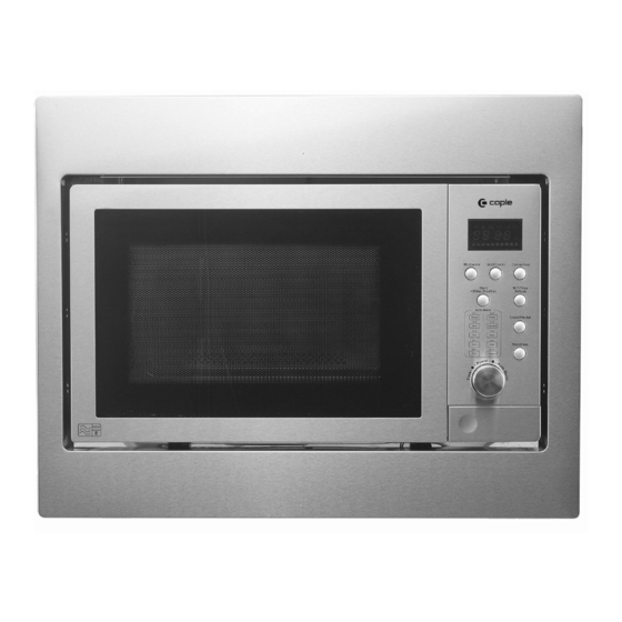
- Page 2 CM118 Microwave, grill and convection oven with frame Features 25L easitronic built-in microwave, grill and convection oven Auto cook menu Auto defrost Child lock 95 minute timer Stainless steel front / cavity Mark resistant finish LED display Stainless steel frame (W 595mm x H 460mm)
- Page 3 Installation Instruction Please Read the Manual Carefully Before Installation Please Note Electrical connection The oven is fitted with a plug and must be only connected to a properly installed earthed socket. In accordance with the appropriate regulations, the socket must only be installed and the connecting cable must only be replaced by a qualified electrician.
- Page 4 B. Prepare the Cabinet. 1. Read the instruction on the BOTTOM CABINET TEMPLATE, put the template on the bottom plane of cabinet. 2. Make marks on the bottom plane of cabinet according to marks “a” of the template.
- Page 5 3. Remove the BOTTOM CABINET TEMPLATE, and fix the BOTTOM BRACKETS with SCREW A. C. Prepare the oven. 4. Fix SCRE W B on the UPPER AIR TUNNEL of the oven.
- Page 6 D. Install the oven. 5. Install the oven into the cabinet. Adjust the height of SCREW B to keep 1mm gap between the SCREW B and the top plane of cabinet. Make sure that the OVEN FEET are aligned with the grooves of brackets when install the oven into the cabinet.
- Page 9 CM118 - Caple BI Combi M.wave & Grill Position Part Number Description 251500100594 ASS'Y CAVITY 252100100016 COVER WAVE GUIDE 261501409903 BASE PLATE 251302000013 251502501540 ASS'Y BRKT HINGE *U 251300201809 PANEL CONTROL 261506911320 DECO. C/PANEL 251306003205 BUTTON DOOR OPEN 252010100001 SPRING BUTTON...
- Page 10 CM118 - Caple BI Combi M.wave & Grill Position Part Number Description F02+F03 -253602110803 261314202300 TRIM PANEL 261314300300 TRIM DECO 251514101581 KNIGHTHEAD 251201700033 HEATER *T 261502700100 INSULATOR HEAT *T 261301301500 BRKT INTERLOCK 261301101000 LEVER SWITCH 261201600180 MICROSWITCH INTERLOCK 261201600160 MICROSWITCH MONITOR...
- Page 11 CM118 - Caple BI Combi M.wave & Grill Position Part Number Description 251900100147 PACKING *T 251900200146 PACKING *U 251511701176 RACK 261800304335 MANUAL USER 261862500389 CARTON BOX 261800200010 MIDEA MANUAL USER -253602100890 (ALL COMPONENTS BELOW) 252012500477 WASHER 251517201582 SPACER BRKT 252012800011...
-
Page 12: Safety Precautions
SAFETY PRECAUTIONS This device is to be serviced only by properly qualified service personnel. Consult the service manual for proper service procedures to assure continued safety operation and for precautions to be taken to avoid possible exposure to excessive microwave energy. PRECAUTIONS TO BE OBSERVED BEFORE AND DURING SERVICING TO AVOID POSSIBLE EXPOSURE TO EXCESSIVE MICROWAVE ENERGY... -
Page 13: Table Of Contents
TABLE OF CONTENTS (page) SAFETY PRECAUTIONS------------------------------------ ------Inside front cover --------------- CAUTIONS------------------------------------------------------------------------------------------------1-1 THE HEATING PRINCIPLE OF MICROWAVE--------------------------------------------------2-1 INSTALLATIONS----------------------------------------------------------------------------------------3-1 OPERATING INSTRUCTIONS----------------------------------------------------------------------4-1 SCHEMATIC DIAGRAM--------------------------------------------------------------------------4-1 CIRCUIT DESCRIPTION-------------------------------------------------------------------------4-2 SERVICE INFORMATION-----------------------------------------------------------------------------5-1 TOOLS AND MEASURING INSTRUMENTS------------------------------------------------5-1 MICROWAVE LEAKAGE TEST----------------------------------------------------------------5-2 MEASUREMENT OF MICROWAVE POWER OUTPUT---------------------------------5-3 TROUBLE SHOOTING PROCEDURES------------------------------------------------------5-4 COMMON BREAKDOWN AND MEANS OF REPAIRING-------------------------------5-8 IMPORTANT THINGS TO DO PRIOR TO CRITICAL PART SERVICING-------------------------5-9 SAFETY CHECKS AND TESTS AFTER SERVING--------------------------------------5-10... - Page 14 Unlike other appliances, the microwave oven MICROWAVE RADIATION high-voltage and high-current equipment. Personnel should not be exposed to the Though it is free from danger in ordinary use, microwave energy which may radiate from the extreme care should be taken during repair. magnetron or other microwave generating device if it is improperly used or connection.
-
Page 15: The Heating Principle Of Microwave
THE HEATING PRINCIPLE OF MICROWAVE Microwave is one kind of radio wave whose wave length is very short, frequency is very high. Therefore, it is called ultrahigh frequency electromagnetic wave. Microwave can heat food mainly result in the mutual affect of the food in the microwave field and microwave field itself. -
Page 16: Installations
INSTALLATIONS BEFORE YOU BEGIN, READ THE FOLLOWING INSTRUCTIONS COMPLETELY INSTALLING EARTHING INSTRUCTIONS 1. Empty the microwave oven and clean inside it with This microwave oven is designed to be used in a fully a soft, damp cloth. Check for damage such as earthed condition. - Page 17 AC925BBR-SACE...
-
Page 18: Circuit Description
CIRCUIT DESCRIPTION As the door is closed, the contact of MONITOR • 3.2 volts AC is generated from the filament winding of SWITCH opens. This switch creates the short circuit to the high voltage transformer. This 3.2 volts is applied blow fuse during operation under abnormal condition. -
Page 19: Service Information
SERVICE INFORMATION TOOLS AND MEASURING INSTRUMENTS NECESSARY TOOLS NECESSARY MEASURING Tools normally used for TV servicing are sufficient. INSTRUMENTS Standard tools are listed below. • TESTER(VOLTS-DC, AC., Ohmmeter) • Diagonal pliers • Microwave survey meter • Long nose pliers - Holaday HI-1710(A) •... - Page 20 MEASUREMENT WITH OUTER CASE NOTES WHEN MEASURING REMOVED • Do not exceed meter full scale deflection. • When you replace the magnetron, measure for • The test probe must be removed no faster than microwave energy leakage before the outer case is 1 inch/sec (2.5 cm/sec) along the shaded area, installed and after all necessary components are otherwise a false reading may result.
-
Page 21: Measurement Of Microwave Power Output
MEASUREMENT OF MICROWAVE POWER OUTPUT • Microwave power output measurement is made with • The microwave power output P in watts is the microwave oven supplied at its rated voltage and calculated operated at its maximum microwave power setting with approximately from the following formula : a load of (1000±5) g of potable water. -
Page 22: Trouble Shooting Procedures
TROUBLE SHOOTING PROCEDURES Before overhauling a microwave oven, you should judge the breakdown and the cause correctly, then you can repair it with corresponding ways. The overhauling must be proceed in order, any hasty conclusion is not recommendable, otherwise overworking would be done when repair. The microwave oven may occur compound breakdown due to all kinds of different reasons, thus, when overhaul, they all should be taken into consideration. - Page 23 Examine when the oven at operating, but the food can’t be heated Pull out the power plug, take off the outer case, discharge the capacitor, measure the resistance value of the primary winding and the secondary winding of the transformer with a multi meter (FIG.5-3 and FIG.5-4). The resistance value of the primary winding should be about 2.2 ohm, the secondary winding should be about 130 ohm, otherwise, it indicates the transformer has broken, and should be replaced by a new one.
- Page 24 FIG5.10 FIG.5-9 Ⅲ.REPAIRING METHOD OF SEVERAL BREAKDOWN Repair when there occurred large amounts microwave leakage. There are many factors, which may cause microwave leaking. Following mentioned may be the main cause of microwave leakage: (1) The door deformed, the hinge loosed or damaged that caused the door can not close tightly. (2) The door pressing cover or the embed piece damaged or come off.
- Page 25 Means of repair when the oven can heat, but the turntable glass can’t move Firstly, check whether the turntable holder is placed correctly. If it is correct, then pull out the power plug and take down the turntable combination, measure the resistance value of the turntable motor with Rx1k grade of a multi meter If it is open- circuited, it indicates the turntable motor has broken, and should be replaced by a new, same model one.
- Page 26 MOTOR TEST PROCEDURE COMPONENTS TEST PROCEDURE RESULTS Measure the resistance. Fan Motor (Ohm-meter scale:R×100) Normal:Approx. 47Ω (Wire leads removed) ∞ Abnormal: or Several Ω Measure the resistance. Turntable Motor (Ohm-meter scale:R×1000) Normal:Approx. 3.2kΩ (Wire leads removed) ∞ Abnormal: or Several Ω NOTE: A MICROWAVE LEAKGE TEST MUST ALWAYS BE PERFORMED WHEN THE UNIT IS SERVICED FOR ANY REASON.
-
Page 27: Common Breakdown And Means Of Repairing
COMMON BREAKDOWN AND MEANS OF REPAIRING PHENOMENON CAUSE REPAIRING MEANS 1. fuse broken 1. Change a new fuse. 2. The primary and secondary winding of the 2. Change transformer are short-circuited. transformer. 1.When starting 3. The earthing or the polarity of the capacitor is 3. -
Page 28: Important Things To Do Prior To Critical Part Servicing
IMPORTANT THINGS TO DO PRIOR TO CRITICAL PART SERVICING The following instructions are CRITICAL to the owner’s safety. Be sure to follow all the instructions. Contact the manufacturer of distributor if you have any question. If the oven is operative prior to servicing a Microwave Leakage Test (Microwave Emission Check) should be performed prior to servicing the oven. -
Page 29: Safety Checks And Tests After Serving
SAFETY CHECKS AND TESTS AFTER SERVING Constructional Checks If mechanical or electrical(electronic) parts have been replaced be sure to follow the following steps. Check for correct wiring, adequate mechanical decrements of parts, and firm connectors. Check for adequate grounding. Check the following items before turning the oven ON. Proper door closing, seal/choke surfaces, and hinges.
Need help?
Do you have a question about the CM118 and is the answer not in the manual?
Questions and answers