
Related Manuals for Circutor AFQm IP54


Summary of Contents for Circutor AFQm IP54
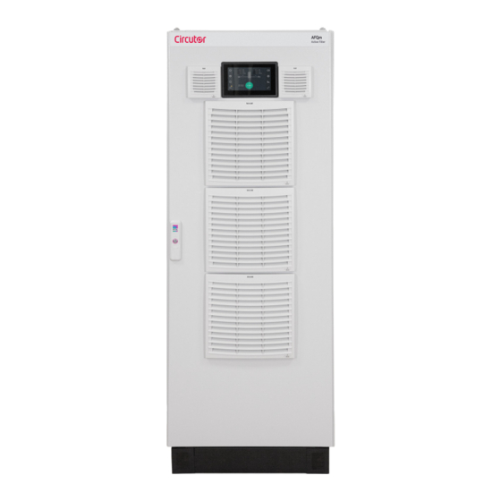
- Page 1 Filtro Activo Paralelo Multifunción Active Parallel Multi-Function Filter AFQm IP54 MANUAL DE INSTRUCCIONES INSTRUCTION MANUAL (M308B01-20-21A)
- Page 2 AFQm IP54...
-
Page 3: Contenido - Contents
AFQm IP54 CONTENIDO - CONTENTS MANUAL DE INSTRUCCIONES ............................4 INSTRUCTION MANUAL ..............................89... -
Page 4: Precauciones De Seguridad
En el presente manual, si las instrucciones precedidas por este símbolo no se respetan o realizan correctamente, pueden ocasionar daños personales o dañar el equipo y /o las instalaciones. CIRCUTOR, SA se reserva el derecho de modificar las características o el manual del producto, sin previo aviso. LIMITACIÓN DE RESPONSABILIDAD CIRCUTOR, SA se reserva el derecho de realizar modificaciones, sin previo aviso, del equipo o a las especificaciones del equipo, expuestas en el presente manual de instrucciones. -
Page 5: Table Of Contents
AFQm IP54 CONTENIDO CONTENIDO - CONTENTS ..............................3 PRECAUCIONES DE SEGURIDAD ............................4 LIMITACIÓN DE RESPONSABILIDAD .............................4 CONTENIDO ...................................5 HISTÓRICO DE REVISIONES ..............................7 SÍMBOLOS ..................................... 7 1.- COMPROBACIONES A LA RECEPCIÓN ..........................8 1.1.- PROTOCOLO DE RECEPCIÓN .............................8 1.2.- TRANSPORTE Y MANIPULACIÓN ..........................8 1.3.- ALMACENAJE ................................9... - Page 6 9.2.- PÁGINA WEB ................................75 10.- MANTENIMIENTO ................................77 10.1.- MANTAS FILTRANTES ............................78 10.2.- MANTENIMIENTO DE LOS PROTECTORES DE SOBRETENSIÓN: AFQm IP54 DE 70A, 140A, 210A Y 280A ..79 11.- CARACTERÍSTICAS TÉCNICAS ............................. 80 12.- SERVICIO TÉCNICO ..............................85 13.- GARANTÍA ................................... 85 14.- CERTIFICADO CE .................................
-
Page 7: Histórico De Revisiones
AFQm IP54 HISTÓRICO DE REVISIONES Tabla 1: Histórico de revisiones. Fecha Revisión Descripción 07/20 M308B01-20-20A Versión Inicial Modificaciones en los siguientes apartados: 02/21 M308B01-20-21A 2. - 3.5. - 3.6. - 3.8. - 10. - 10.2. - 11. SÍMBOLOS Tabla 2: Símbolos. -
Page 8: Comprobaciones A La Recepción
Realizar una inspección visual externa e interna del equipo antes de conectarlo. Si observa algún problema de recepción contacte de inmediato con el transportis- ta y/o con el servicio postventa de CIRCUTOR. 1.2.- TRANSPORTE Y MANIPULACIÓN El transporte, carga y descarga y manipulación del equipo debe llevarse a cabo con las precauciones y las herramientas manuales o mecánicas adecuadas para evitar... -
Page 9: Almacenaje
Al desembalar el equipo, tenga cuidado en caso de utilizar herramientas cortantes tipo cúter, tijeras o cuchillo, de no estropear el equipo. Los equipos AFQm IP54 tipo armario, incorporan 4 anillas (28 mm de diámetro) en el techo para su trasporte mediante grúa. El techo se encuentra invertido, pero las anillas están montadas, para permitir su transporte sin necesidad de ninguna operación previa. -
Page 10: Descripción Del Producto
Compensar la potencia reactiva. Tanto de corrientes atrasadas (inductiva) como adelantadas (capacitiva). Los AFQm IP54 tienen una envolvente tipo armario con una protección reforzada frente a la entrada de polvo y agua, lo que permite instalar el equipo de forma segura en lugares polvorientos o donde se puedan producir salpicaduras de agua. - Page 11 AFQm IP54 Tabla 3 (Continuación): Relación de modelos AFQm IP54. 3 Hilos 4 Hilos Tensión de red Modelo Corriente ( L1, L2, L3) ( L1, L2, L3, N) (Un) AFQm-3WF-280C-690 280 A 230 ... 690 V AFQm-4WF-280C-550 280 A 230 ...
-
Page 12: Instalación Del Equipo
AFQm IP54 3.- INSTALACIÓN DEL EQUIPO 3.1.- RECOMENDACIONES PREVIAS La instalación del equipo y las operaciones de mantenimiento debe realizarse solo por personas autorizadas y cualificadas. Para la utilización segura del equipo es fundamental que las personas que lo manipulen sigan las medidas de seguridad estipuladas en las normativas del país donde se está... -
Page 13: Emplazamiento
El AFQm IP54 utiliza una refrigeración con una entrada de aire por el frontal, y una salida de aire por la parte trasera del equipo. Es necesario dejar espacio en la parte trasera del armario, un mínimo de 150 mm. -
Page 14: Almacenamiento Durante Un Largo Periodo
Alimentar el equipo y dejarlo en modo STOP 3.4.- INSTALACIÓN Los modelos AFQm IP54 tipo Armario, son armarios autoportantes con 4 puntos de apoyo en el suelo. Es obligatorio que la superficie de montaje sea sólida, soporte el peso del equipo, y se encuentre nivelada. -
Page 15: Conexión
En caso de que la legislación local obligue a usar dispositivos de protección frente a corriente a tierra, con los AFQm IP54 solo se deben usar RCD sensibles a AC/DC (RCD tipo B). Los filtros activos funcionan internamente con corrientes DC, en caso de fallo, las corrientes DC pueden provocar un mal funcionamiento de las protecciones tipo A. -
Page 16: Bornes Del Equipo
Figura 4: No instalar varios filtros activos en serie. 3.6.- BORNES DEL EQUIPO Los AFQm IP54 tienen sus conexiones en la parte inferior del armario. Se deben utilizar las ventanas inferiores del armario para pasar los cables al interior del equipo, Figura 5 En caso de posible entrada de polvo por el suelo del equipo, se deberán mecanizar dichas ventanas y... - Page 17 Reemplazar de forma inmediata aquellos con el indicador en color rojo. Seguir las instrucciones de mantenimiento descritas en el apartado “10.2.- MANTENIMIENTO DE LOS PROTECTORES DE SOBRETENSIÓN: AFQm IP54 DE 70A, 140A, 210A Y 280A” Una vez abierta la tapa frontal, se accede a los bornes del equipo, Figura 7 y Figura 8 Figura 7: Bornes AFQm IP54.
- Page 18 AFQm IP54 Figura 8: Borne de tierra en AFQm IP54. Tabla 6: Relación de bornes. Bornes del equipo 1: S1, Entrada de corriente L1 6: S2, Entrada de corriente L3 2: S2, Entrada de corriente L1 7: L1, Conexión a la Red L1 3: S1, Entrada de corriente L2 8: L2, Conexión a la Red L2...
- Page 19 3: OUT, Salida para la conexión en paralelo Los bornes de los puertos de comunicaciones RS-485 y Ethernet se encuentran en la parte posterior de la pantalla frontal del AFQm IP54, ver Figura 10 Figura 10: Bornes de los puertos de comunicación.
-
Page 20: Esquemas De Conexionado
AFQm IP54 3.7.- ESQUEMAS DE CONEXIONADO 3.7.1.- CONEXIÓN A 4 HILOS Y MEDIDA DE CORRIENTE EN EL LADO DE RED. RED/ MAINS P2 S1 P2 S1 CARGA / LOAD Figura 11: Medida trifásica con conexión a 4 hilos y medida de corriente en el lado de Red. -
Page 21: Conexión A 4 Hilos Y Medida De Corriente En El Lado De Carga
AFQm IP54 3.7.2.- CONEXIÓN A 4 HILOS Y MEDIDA DE CORRIENTE EN EL LADO DE CARGA. RED/ MAINS CARGA / LOAD P2 S1 P2 S1 Figura 12: Medida trifásica con conexión a 4 hilos y medida de corriente en el lado de Carga. -
Page 22: Conexión A 3 Hilos Y Medida De Corriente En El Lado De Red
AFQm IP54 3.7.3.- CONEXIÓN A 3 HILOS Y MEDIDA DE CORRIENTE EN EL LADO DE RED. CARGA / LOAD RED/ MAINS P2 S1 P2 S1 Figura 13: Medida trifásica con conexión a 3 hilos y medida de corriente en el lado de Red. -
Page 23: Conexión A 3 Hilos Y Medida De Corriente En El Lado De Carga
AFQm IP54 3.7.4.- CONEXIÓN A 3 HILOS Y MEDIDA DE CORRIENTE EN EL LADO DE CARGA. CARGA / LOAD RED/ MAINS P2 S1 P2 S1 Figura 14: Medida trifásica con conexión a 3 hilos y medida de corriente en el lado de Carga. -
Page 24: Conexión A 3 Hilos Y 2 Transformadores De Corriente En El Lado De Red
AFQm IP54 3.7.5.- CONEXIÓN A 3 HILOS Y 2 TRANSFORMADORES DE CORRIENTE EN EL LADO DE RED. RED/ MAINS CARGA / LOAD Figura 15: Medida trifásica con conexión a 3 hilos y 2 transformadores de corriente en el lado de Red. -
Page 25: Conexión A 3 Hilos Y 2 Transformadores De Corriente En El Lado De Carga
AFQm IP54 3.7.6.- CONEXIÓN A 3 HILOS Y 2 TRANSFORMADORES DE CORRIENTE EN EL LADO DE CARGA. RED/ MAINS CARGA / LOAD Figura 16: Medida trifásica con conexión a 3 hilos y 2 transformadores corriente en el lado de Carga. -
Page 26: Conexionado De 2 A 100 Filtros Activos En Paralelo
AFQm IP54 3.8.- CONEXIONADO DE 2 A 100 FILTROS ACTIVOS EN PARALELO Los equipos AFQm IP54 permiten su colocación en paralelo para incrementar la potencia de filtrado disponible. Es posible colocar hasta 100 equipos en paralelo, de los modelos de 70A y 100A. - Page 27 Esclavo AFQm-xxx-200C (*) Conexiones ya incluidas en los armarios Figura 19: Conexión de 3 equipos en paralelo, mediante el cable de comunicaciones (Maestro AFQm IP54 200A). 5.- Realizar la configuración de la instalación en el equipo “maestro” (ver “7.- CONFIGURACIÓN”...
-
Page 28: Funcionamiento
AFQm IP54 4.- FUNCIONAMIENTO 4.1.- ARMÓNICOS Las cargas no lineales tales como: rectificadores, inversores, variadores de velocidad, hornos, etc, ab- sorben de la red corrientes periódicas no senoidales. Estas corrientes están formadas por una componente fundamental de frecuencia 50 ó 60 Hz, más una serie de corrientes superpuestas de frecuencias múltiplos de la fundamental, que denominamos... -
Page 29: Armónicos Más Habituales
�������� �������� ∗ 100 �������� �������� �������� �������� AFQm IP54 �������� ∗ 100 �������� �������� �������� ���� ���� ∗ 100 ���� Tasa de distorsión individual (U % o I %): Relación en % entre el valor eficaz de la tensión o ����... -
Page 30: Compensación De Armónicos
AFQm IP54 Tabla 11: Armónicos más habituales. Tipo de carga Forma de onda Espectro armónico THD(I) Convertidores 6 pulsos Variadores de velocidad Rectificadores trifásicos Convertidores para electrólisis y baños Lámparas de descarga Convertidores monofásicos Líneas de iluminación Líneas de ordenadores Equipos de imagen y sonido 4.1.3.- COMPENSACIÓN DE ARMÓNICOS... -
Page 31: Principio De Funcionamiento
El filtro activo adquirido debe estar dimensionado para las corrientes de armónicos que debe filtrar. La corriente nominal del AFQm IP54 debe ser como mínimo un 20% superior al nivel máximo de armóni- cos a filtrar. Este factor puede ser mayor según las características de la instalación. - Page 32 ���� = ����� + ���� + ���� + ���� + ⋯ AFQm IP54 Para evitar este fenómeno conviene sobredimensionar el filtro activo multiplicando la corriente inicial ����� + ���� + ���� + ⋯ ������������ ( ���� ) % = de armónicos medida en la carga por un factor de seguridad (FS ).
-
Page 33: Detección De Resonancia
En algún caso, puede existir alguna carga que ofrezca una menor impedancia que la red eléctrica, en cuyo caso se producirá un fenómeno de resonancia con esa carga. El AFQm IP54 dispone de un siste- ma de detección de resonancia con cargas, que automáticamente desactiva el armónico que provoca esa resonancia. -
Page 34: Protección Térmica
AFQm IP54 4.6.- PROTECCIÓN TÉRMICA El equipo dispone de varios niveles de protección térmica: Regulación de la ventilación, la velocidad de los ventiladores se ajusta según la necesidad en cada momento, minimizando así el ruido del equipo. Limitación estática de la temperatura, el equipo reduce su potencia si la temperatura interna supera unos límites establecidos. -
Page 35: Área Central
AFQm IP54 El display se divide en dos áreas ( Figura 26 Área central Áreas laterales Figura 26: El display se divide en dos áreas. 4.7.1.- ÁREA CENTRAL En el área central se visualiza: El estado de la instalación, ... - Page 36 AFQm IP54 RICA” El símbolo indica que el equipo tiene consejos pendientes de leer. El equipo analiza de forma conti- nua su comportamiento y su interacción con la instalación. En base a ese análisis, puede ofrecer con- sejos para optimizar el funcionamiento global del sistema. Una vez leídos, desaparece el icono, hasta que haya nuevos consejos.
-
Page 37: Puesta En Marcha
AFQm IP54 5.- PUESTA EN MARCHA Una vez alimentado el equipo en el display aparece la pantallas de la Figura 27 Figura 27: Pantalla inicial. Antes de arrancar el filtro activo es necesario seguir los siguientes pasos: 1.- Acceder a las pantallas de configuración, y realizar la configuración adecuada según la insta-... -
Page 38: Visualización
En la parte inferior izquierda de la pantalla se visualiza un mensaje con el estado actual del equipo Tabla 13 Tabla 13: Mensajes de estado Mensajes de Estado Arrancando Descripción AFQm IP54 arrancando. Iniciando Descripción Equipo iniciando los sistemas. Esperando comms Descripción Iniciando sistemas de comunicación internos... -
Page 39: Equipo Esclavo
Tabla 13 (Continuación): Mensajes de estado Mensajes de Estado Marcha Descripción Equipo en funcionamiento. Sincronizando Descripción El AFQm IP54 está sincronizando con la Red. Cargando bus DC Descripción Proceso de carga del bus interno previo al arranque. Parado Descripción Equipo parado. -
Page 40: Pantallas De Valores Numéricos
AFQm IP54 6.2.- PANTALLAS DE VALORES NUMÉRICOS Para acceder a las pantallas de valores numéricos es necesario pulsar sobre Nota: Realizar un desplazamiento con el dedo, hacia la derecha o la izquierda para desplazarse por las diferentes pantallas de visualización. -
Page 41: Corriente Armónica
AFQm IP54 6.2.3.- CORRIENTE ARMÓNICA En la se muestra la corriente armónica en valor absoluto de cada una de las fases en la Red Figura 32 y en la Carga. Figura 32: Corriente armónica 6.2.4.- TABLA DE ARMÓNICOS En esta pantalla, , se visualizan de forma tabular, todos los armónicos de tensión, corriente de... -
Page 42: Tensión / Corriente / Frecuencia
AFQm IP54 6.2.5.- TENSIÓN / CORRIENTE / FRECUENCIA En la se muestra la pantalla de Tensión, Corriente y Frecuencia. Figura 34 Figura 34: Visualización de la Tensión, Corriente y Frecuencia. Donde se visualiza: La Tensión en cada una de las fases, L1, L2 y L3. -
Page 43: Potencia Y Cos ɸ De Carga
AFQm IP54 6.2.7.- POTENCIA Y COS ɸ DE CARGA se muestra la potencia y el cos ɸ de la carga. En la Figura 36 Figura 36: Visualización de la potencia y cos ɸ de la carga. Donde se visualiza: La Potencia Activa (P), Reactiva (Q) y Aparente (S). -
Page 44: Fasores De Red
AFQm IP54 6.3.2.- FASORES DE RED En esta pantalla, , se visualizan los fasores de red. Figura 38 Figura 38: Fasores de Red. 6.4.- PANTALLAS DE ARMÓNICOS Para acceder a las pantallas de armónicos es necesario pulsar sobre Nota: Realizar un desplazamiento con el dedo, hacia la derecha o la izquierda para desplazarse por las diferentes pantallas de visualización. -
Page 45: Armónicos De Corriente (Carga)
AFQm IP54 6.4.2.- ARMÓNICOS DE CORRIENTE (CARGA) En esta pantalla, , se visualizan los armónicos impares de la corriente de carga, del 3 al 25, de Figura 40 cada una de las fases. Figura 40: Visualización de los armónicos de la corriente de carga. -
Page 46: Pantallas De Formas De Onda
AFQm IP54 6.5.- PANTALLAS DE FORMAS DE ONDA Para acceder a las pantallas de formas de onda es necesario pulsar sobre Nota: Realizar un desplazamiento con el dedo, hacia la derecha o la izquierda para desplazarse por las diferentes pantallas de visualización. -
Page 47: Forma De Onda De La Corriente De Red
AFQm IP54 6.5.3.- FORMA DE ONDA DE LA CORRIENTE DE RED En esta pantalla, , se visualiza la forma de onda de la corriente de Red de cada una de las Figura 44 fases. Figura 44: Forma de onda de la corriente de red. -
Page 48: Comunicaciones Ethernet
AFQm IP54 6.6.2.- COMUNICACIONES ETHERNET En esta pantalla, , se visualizan la dirección IP del equipo y la mascara de red. Figura 46 Figura 46: Comunicaciones. 6.6.3.- INFORMACIÓN DEL EQUIPO En esta pantalla, , se visualiza el número de serie y las versiones HMI y DSP del equipo. -
Page 49: Información Del Fabricante
AFQm IP54 6.6.4.- INFORMACIÓN DEL FABRICANTE , se visualiza la información sobre CIRCUTOR. En esta pantalla, Figura 48 Figura 48: Información del fabricante. 6.7.- PANTALLAS DE ALARMAS Y ADVERTENCIAS Para acceder a las pantallas de alarmas y advertencias necesario pulsar sobre Nota: Realizar un desplazamiento con el dedo, hacia la derecha o la izquierda para desplazarse por las diferentes pantallas de visualización. - Page 50 Tabla 14: Mensajes de alarma. Mensajes de alarma Sobrecorriente L1/L2/L3 Descripción La corriente del AFQm IP54 es demasiado alta. Acción Esta alarma puede ir asociada a transitorios y ruido en la tensión de alimentación. Comprobar la cali- correctora dad de tensión de alimentación. Si persiste, contactar con SAT Sobretensión red L1/L2/L3...
-
Page 51: Advertencias
AFQm IP54 Tabla 14 (Continuación): Mensajes de alarma. Mensajes de alarma Condiciones Iniciales Descripción Se han incumplido 10 veces las condiciones de arranque en 5 minutos. Acción Revisar configuración y comprobar la temperatura ambiente. Comprobar la calidad de tensión de correctora alimentación. - Page 52 AFQm IP54 Figura 52: Advertencias. Tabla 15:Mensajes de advertencias. Mensajes de advertencias Esperando condiciones Descripción No se cumplen las condiciones de arranque. Acción Revisar mensajes de avisos. correctora Polaridad carga Descripción Detección de error en polaridad de la carga. Acción Comprobar conexionado de transformadores.
- Page 53 AFQm IP54 Tabla 15 (Continuación): Mensajes de advertencia. Mensajes de advertencias Límites frecuencia de red Descripción Frecuencia de red fuera de límites Este aviso puede ir asociado a transitorios y ruido en la tensión de alimentación, o a valores de fre- Acción...
-
Page 54: Configuración
AFQm IP54 7.- CONFIGURACIÓN Para acceder a las pantallas de configuración es necesario pulsar sobre Nota: Realizar un desplazamiento con el dedo, hacia la derecha o la izquierda para desplazarse por las diferentes pantallas de visualización. En la, , se muestra la pantalla inicial de configuración. -
Page 55: Idioma
AFQm IP54 7.1.- IDIOMA En esta pantalla, , se selecciona el idioma del display. Figura 55 Figura 55: Pantalla de configuración: Idioma. ● Idioma, idioma del display. Pulsar la tecla para guardar la configuración modificada. 7.2.- ESPECIFICACIONES DEL EQUIPO Nota: Esta pantalla es informativa, no se puede modificar. -
Page 56: Equipos Instalados
En esta pantalla se selecciona el tipo de equipo, las posibles opciones son: Único: seleccionar esta opción si el AFQm IP54 no tiene filtros conectados en paralelo. Maestro: seleccionar esta opción si el filtro va a trabajar como “maestro” de un grupo de equipos en paralelo. -
Page 57: Modo De Trabajo
AFQm IP54 7.4.- MODO DE TRABAJO Nota: Esta pantalla no es visible en los equipos “esclavos”. En esta pantalla, , se configuran los siguientes parámetros del modo de trabajo de equipo: Figura 58 Figura 58: Pantalla de configuración: Modo de trabajo. - Page 58 AFQm IP54 La opción de equilibrado de fases en el AFQm-3WF-xxxx funciona en desequilibrios producidos por cargas conectadas entre fases en redes trifásicas sin neutro. El AFQm- 3WF-xxxx no compensa desequilibrios producidos por cargas monofásicas conectadas entre fase y neutro. Para corregir este tipo de desequilibrios utilizar un AFQm-4WF- xxxx.
-
Page 59: Selección De Armónicos
En este parámetro se configura la corriente mínima de la carga para arrancar el filtro. La corriente mínima se utiliza para incrementar la eficiencia del sistema, manteniendo en standby el filtro cuando se requiera. El AFQm IP54 se parará cuando la corriente de carga sea inferior al valor introducido y Manual de Instrucciones... -
Page 60: Cos Φ
AFQm IP54 arrancará cuando sea mayor. Rango de valores: Valor mínimo: 0 A Valor máximo: 5000 A ● Limite corriente Este parámetro permite limitar la potencia máxima del filtro activo. El valor se configura en porcentaje respeto a la potencia nominal del equipo. -
Page 61: Ieee519
AFQm IP54 configurada. Este modo permite minimizar la potencia del equipo usada para compensar la reactiva, y por lo tanto, reducir su consumo energético. Rango de valores: 0.7 ... -0.7 Pulsar la tecla para guardar la configuración modificada. 7.8.- IEEE519 Nota: Esta pantalla no es visible en los equipos “esclavos”. - Page 62 AFQm IP54 sitos de los límites establecidos, en lugar de buscar la cancelación total de armónicos. ● Generator La norma IEEE519-2014 establece unos límites más restrictivos si la instalación es generadora. Por ello es necesario marcar la casilla correspondiente en caso de que pueda exportar energía.
-
Page 63: Configuración De Los Transformadores
CARGA: Si se han instalado los transformadores en la zona de la carga, aguas abajo del AFQm IP54. RED: Si se han instalado los transformadores en la zona de red, aguas arriba del AFQm IP54. ● Relación En este parámetro se configura el ratio de los transformadores, es decir la relación entre el primario y el secundario del transformador. -
Page 64: Alarmas
AFQm IP54 Rango de valores: Valor mínimo: 5 A Valor máximo: 5000 A ● Invertir En este parámetro se selecciona la fase sobre la que el filtro va a invertir el sentido de la corriente de los transformadores de medida de carga, de esta manera se pueden corregir errores de instalación. -
Page 65: Comunicaciones Ethernet
7.12.- COMUNICACIONES RS-485 La configuración de las comunicaciones RS-485 en los AFQm IP54, está fijada a una Velocidad de transmisión de 9600 bps, 8 bits de Datos, 1 bit de Stop y Sin Paridad. Únicamente se puede configurar la dirección Modbus del equipo,... -
Page 66: Fecha / Hora
AFQm IP54 7.13.- FECHA / HORA En esta pantalla, , se configuran los parámetros horarios: Figura 67 Figura 67: Pantalla de configuración: Fecha / Hora ● Hora. ● Fecha. ● Zona horaria. Al activar la opción Hora de Internet ☑, el equipo se sincroniza con el horario del servidor Web al que está... - Page 67 AFQm IP54 ● Contraseña de Stop. Es posible introducir una contraseña al acceso de la tecla , si se activa, al pulsar la tecla el equipo solicita la contraseña y no para el equipo si la contraseña no es correcta.
-
Page 68: Comunicaciones Rs-485
AFQm IP54 8.- COMUNICACIONES RS-485 Los AFQm IP54 disponen de una salida de comunicación serie tipo RS-485 con protocolo de comuni- caciones MODBUS RTU ® En una instalación con equipos en paralelo la conexión RS-485 se puede realizar sobre cualquier equi- 8.1.- CONEXIONADO... -
Page 69: Protocolo
AFQm IP54 8.2.- PROTOCOLO Dentro del protocolo Modbus el AFQm IP54 utiliza el modo RTU (Remote Terminal Unit). Las funciones Modbus implementadas en el equipo son: Función 03 y 04: Lectura de n Words (2 bytes). 8.2.1.- EJEMPLO DE PREGUNTA MODBUS... - Page 70 AFQm IP54 Tabla 18: Mapa de memoria Modbus: Medidas en la Carga (Tabla 2). Parámetro Corriente L1 Corriente L2 Corriente L3 Unidades Armónico fundamental 3º Armónico 5º Armónico 7º Armónico 9º Armónico 11º Armónico 13º Armónico 15º Armónico 17º Armónico 19º...
- Page 71 Tabla 24: Mapa de memoria Modbus: Medidas en la Red (Tabla 4). Parámetro Unidades Corriente fundamental Corriente armonicos 8.2.2.3.- Otros parámetros del filtro AFQm IP54 Tabla 25: Mapa de memoria Modbus: Parámetros del filtro (Tabla 1). Parámetro Dirección Unidades Temperatura IGBT 1 ºC con 1 decimal...
- Page 72 Tabla 27: Mapa de memoria Modbus: Parámetros del filtro (Tabla 3). Parámetro Dirección Descripción Nº de serie del AFQm IP54 2710 - 2711 Nº de serie Hi [10] + Low [11] Versión del software del DSP Versión del software HMI En un sistema de equipos en paralelo, el valor del parámetro es el del equipo conectado con RS-485.
- Page 73 En un sistema de equipos en paralelo, el valor del parámetro es el del equipo conectado con RS-485. Tabla 31: Mapa de memoria Modbus: Mensajes del filtro (Tabla 4). Parámetro Dirección Estado del AFQm IP54 Estado ( Valor en decimal) Descripción Arranque 10, 20, 30 Calibración...
- Page 74 AFQm IP54 Tabla 32: Mapa de memoria Modbus: Mensajes del filtro (Tabla 5). Parámetro Dirección Estado de los armónicos Descripción Estado 0x0001 Armónico 3 0x0002 Armónico 5 0x0004 Armónico 7 0x0008 Armónico 9 0x0010 Armónico 11 1: Armónico filtrándose 0x0020 Armónico 13...
-
Page 75: Comunicaciones Ethernet
En una instalación con equipos en paralelo la conexión Ethernet se puede realizar sobre cualquier equipo. 9.1.- CONEXIÓN El AFQm IP54 dispone de un puerto Ethernet. Este tipo de comunicación crea una red interna con comunicaciones vía IP. Si se desea monitorizar remotamente el equipo, se deberá conectar el cable de comunicaciones Ether-... - Page 76 AFQm IP54 El idioma de la página web se puede modificar a partir de los botones que aparecen en la parte supe- rior derecha de la página. Para poder modificar los parámetros de Configuración es necesario introducir el Usuario y Contraseña en el apartado Administrador.
-
Page 77: Mantenimiento
AFQm IP54 10.- MANTENIMIENTO El filtro activo AFQm IP54 requiere un mínimo mantenimiento preventivo. Se recomienda seguir las indicaciones que se describen en este capítulo para evitar un deterioro prematuro de los componentes del equipo. indica las tareas de mantenimiento con sus respectivos intervalos de tiempo. -
Page 78: Mantas Filtrantes
AFQm IP54 10.1.- MANTAS FILTRANTES En el armario AFQm IP54 deben limpiarse las mantas filtrantes incluidas en los filtros de entrada de aire. Los filtros de salida no requieren mantenimiento. Filtros de entrada Figura 72: Filtros de entrada del AFQm IP54. -
Page 79: Mantenimiento De Los Protectores De Sobretensión: Afqm Ip54 De 70A, 140A, 210A Y 280A
AFQm IP54 10.2.- MANTENIMIENTO DE LOS PROTECTORES DE SOBRETENSIÓN: AFQm IP54 DE 70A, 140A, 210A Y 280A El equipo dispone de protectores de sobretensión extraibles, accesibles desde el frontal. Estos incor- poran un indicador de color verde que indica el correcto funcionamiento del protector. -
Page 80: Características Técnicas
AFQm IP54 11.- CARACTERÍSTICAS TÉCNICAS Tensión de red AFQm-3WF-xxxx-480 AFQm-4WF-xxxx-400 208 ... 480 V ~ ± 10% 208 ... 400 V ~ ± 10% Tensión asignada Un AFQm-3WF-xxxx-690 AFQm-4WF-xxxx-550 230 ... 690 V~ ± 10% 230 ... 550 V~ ± 10% Frecuencia Fn 50 / 60 Hz ±... - Page 81 AFQm IP54 AFQm-xxx-070C AFQm-xxx-140C Tensión asignada de aislamiento Ui 690 V 690 V Tensión soportada de impulso Uimp 6kV, CAT III Clase 1 6kV, CAT III Clase 1 Corriente asignada (fase) I 70 A 140 A na fase Corriente asignada (neutro) I...
- Page 82 AFQm IP54 Especificaciones del Filtro Filtrado 2 ... 50 armónico (seleccionable) Tiempo de respuesta < 100 μs Compensación de fases Seleccionable Compensación de la potencia reactiva Seleccionable Programación prioridades Seleccionable Hasta 100 unidades de diferente calibre Paralelización Conexión de los transformadores solo en unidad Master...
- Page 83 AFQm IP54 (Continuación) Características ambientales Resistencia a impactos IK 10 Compatibilidad electromagnética Instalación en entornos tipo A Normas Compatibilidad Electromagnética (CEM). Parte 6-4: Normas genéricas. Norma de EN 61000-6-4:2007 emisión en entornos industriales. (IEC 61000-6-4:2006). Equipos industriales, científicos y médicos. Características de las perturbaciones EN 55011:2011 radioeléctricas.
- Page 84 , el conductor de Tierra puede ser de la mitad de sección que los conductores de fase. (10) Las pletinas de conexión permiten colocar los cables por ambos lados, pudiendo poner dos cables por taladro. Figura 75:Dimensiones AFQm IP54. Manual de Instrucciones...
-
Page 85: Servicio Técnico
13.- GARANTÍA CIRCUTOR garantiza sus productos contra todo defecto de fabricación por un período de dos años a partir de la entrega de los equipos. CIRCUTOR reparará o reemplazará, todo producto defectuoso de fabricación devuelto durante el pe- ríodo de garantía. -
Page 86: Certificado Ce
AFQm IP54 14.- CERTIFICADO CE Manual de Instrucciones... - Page 87 AFQm IP54 Manual de Instrucciones...
- Page 88 AFQm IP54 Manual de Instrucciones...
-
Page 89: Safety Precautions
CIRCUTOR, SA reserves the right to make modifications to the device or the unit specifications set out in this instruction manual without prior notice. CIRCUTOR, SA on its web site, supplies its customers with the latest versions of the device specifica- tions and the most updated manuals. -
Page 90: Contents
AFQm IP54 CONTENTS SAFETY PRECAUTIONS ...............................89 DISCLAIMER ..................................89 CONTENTS ..................................90 REVISION LOG ..................................92 SYMBOLS .....................................92 1.- VERIFICATION UPON RECEPTION ..........................93 1.1.- RECEPTION PROTOCOL ............................93 1.2.- TRANSPORT AND HANDLING ..........................93 1.3.- STORAGE ................................94 2.- PRODUCT DESCRIPTION ...............................95 3.- DEVICE INSTALLATION ..............................97 3.1.- PRELIMINARY RECOMMENDATIONS ........................97... - Page 91 9.2.- WEB SITE ................................160 10.- MAINTENANCE ................................162 10.1.- FILTER MEDIA ..............................163 10.2.- MAINTENACE OF SURGE PROTECTIVE DECIVES: 70A, 140A, 210A AND 280A AFQm IP54 ....... 164 11.- TECHNICAL FEATURES ............................... 165 12.- TECHNICAL SERVICE ..............................170 13.- GUARANTEE ................................170 14.- CE CERTIFICATE ................................171...
-
Page 92: Revision Log
AFQm IP54 REVISION LOG Table 1: Revision log. Date Revision Description 07/20 M308B01-20-20A Initial Version Changes in the following sections: 02/21 M308B01-20-21A 2. - 3.5. - 3.6. - 3.8. - 10. - 10.2. - 11. SYMBOLS Table 2: Symbols. Symbol Description Compliant with the relevant European standards. -
Page 93: Verification Upon Reception
Perform an external and internal visual inspection of the device prior to connecting it. If any problem is noticed upon reception, immediately contact the transport com- pany and/or CIRCUTOR's after-sales service. 1.2.- TRANSPORT AND HANDLING The transport, loading and unloading and handling of the device must be carried out with proper precautions and using the proper manual and mechanical tools so as not to damage it. -
Page 94: Storage
The AFQm IP54 devices cabinet type, there are also 4 rings (diameter : 28 mm) in the top panel so that they can be transported by a crane. The top panel is inverted, but the rings are mounted, to enable it to be transported without any prior set-up required. -
Page 95: Product Description
Correct the power factor. For both backward (inductive) and forward (capacitive) currents. The AFQm IP54 has a cabinet-type enclosure with reinforced protection to keep out dust and water, which allows the device to be safely installed in dusty places or where it may be reached by splashing water. - Page 96 AFQm IP54 Table 3 (Continuation): Relation of models AFQm IP54. 3 Wires 4 Wires Mains voltage Model Current ( L1, L2, L3) ( L1, L2, L3, N) (Un) AFQm-4WF-280C-550 280 A 230 ... 550 V AFQm-3WF-300C-480 300 A 208 ... 480 V ...
-
Page 97: Device Installation
AFQm IP54 3.- DEVICE INSTALLATION 3.1.- PRELIMINARY RECOMMENDATIONS The device installation and the maintenance operations must only be carried out by authorised and qualified personnel. In order to use the device safely, it is critical that individuals who handle it follow the... -
Page 98: Installation Location
“4.6 - THERMAL PROTECTION” The AFQm IP54 uses a cooling system with an air inlet at the front and an air outlet at the rear of the unit. Be sure to leave a gap at the back of the cabinet of at least 150 mm. To ensure this, the device includes spacers at the rear that act as a bumper. -
Page 99: Storage For Long Periods
STOP mode 3.4.- INSTALLATION The Cabinet-type AFQm IP54 models are free-standing cabinets with 4 bearing supports on the floor. The mounting surface must be solid, support the device’s weight and be level. The cabinet must never be welded to the floor using arc welding, as this may destroy the electronic components. -
Page 100: Connection
These sections are for informative purposes only. The conductor cross-section must be selected according to the current, prevailing regulations, cable type and type of wiring installation. Ensure that the AFQm IP54 is earthed correctly to prevent the risk of electric shock. To measure the current, class 0.2S transformers of the TC or TCH series are recom- mended. -
Page 101: Device Terminals
Figure 4: Do not install various active filters in series. 3.6.- DEVICE TERMINALS The connections on the AFQm IP54 are located at the bottom of the cabinet. The lower windows on the cabinet have to be used to route the cables into the device,... - Page 102 The green lights on the surge voltage protection indicate that they are working cor- rectly. Immediately replace those whose indicator is red, see “10.2.- MAINTENANCE OF SURGE PROTECTIVE DEVICES:70A, 140A, 210A AND 280A AFQm IP54” Once the front cover is open, the device’s terminals can be accessed, Figure 7 Figure 8 Figure 7: AFQm IP54 terminals.
- Page 103 AFQm IP54 Figure 8: AFQm IP54 earth terminal. Table 6: List of terminals. Device terminals 1: S1, Current input L1 6: S2, Current input L3 2: S2, Current inpu 7: L1, Mains connection L1 3: S1, Current input L2 8: L2, Mains connection L2...
- Page 104 2: IN, Input for parallel connection 3: OUT, Output for parallel connection The terminals of the RS-485 and Ethernet communications ports are located at the back of the front screen on the AFQm IP54, see Figure 10. Figure 10: Terminals of the communication ports.
-
Page 105: Connection Diagrams
AFQm IP54 3.7.- CONNECTION DIAGRAMS 3.7.1.- 4-WIRE CONNECTION AND CURRENT MEASUREMENT ON THE MAINS SIDE. RED/ MAINS P2 S1 P2 S1 CARGA / LOAD Figure 11: Three-phase measuring with 4-wire connection and current measurement on the mains side. Use the 2 neutral current terminals, as In can be:In ≈ 3 * I... -
Page 106: 4-Wire Connection And Current Measurement On The Load Side
AFQm IP54 3.7.2.- 4-WIRE CONNECTION AND CURRENT MEASUREMENT ON THE LOAD SIDE. RED/ MAINS CARGA / LOAD P2 S1 P2 S1 Figure 12: Three-phase measuring with 4-wire connection and current measurement on the load side. Use the 2 neutral current terminals, as In can be: In ≈ 3 * I... -
Page 107: 3-Wire Connection And Current Measurement On The Mains Side
AFQm IP54 3.7.3.- 3-WIRE CONNECTION AND CURRENT MEASUREMENT ON THE MAINS SIDE. CARGA / LOAD RED/ MAINS P2 S1 P2 S1 Figure 13: Three-phase measuring with 3-wire connection and current measurement on the mains side. Instruction Manual... -
Page 108: 3-Wire Connection And Current Measurement On The Load Side
AFQm IP54 3.7.4.- 3-WIRE CONNECTION AND CURRENT MEASUREMENT ON THE LOAD SIDE. CARGA / LOAD RED/ MAINS P2 S1 P2 S1 Figure 14: Three-phase measuring with 3-wire connection and current measurement on the load side. Instruction Manual... -
Page 109: 3-Wire Connection And 2 Current Transformers On The Mains Side
AFQm IP54 3.7.5.- 3-WIRE CONNECTION AND 2 CURRENT TRANSFORMERS ON THE MAINS SIDE. RED/ MAINS CARGA / LOAD Figure 15: Three-phase measuring with a 3-wire connection and 2 current transformers on the mains side. The connection of 2 current transformers is only possible in three-phase mains without neutral (3 wires). -
Page 110: 3-Wire Connection And 2 Current Transformers On The Load Side
AFQm IP54 3.7.6.- 3-WIRE CONNECTION AND 2 CURRENT TRANSFORMERS ON THE LOAD SIDE. RED/ MAINS CARGA / LOAD Figure 16: Three-phase measuring with a 3-wire connection and 2 current transformers on the load side. The connection of 2 current transformers is only possible in three-phase mains without neutral (3 wires). -
Page 111: Parallel Connection Of 2 To 100 Active Filters
AFQm IP54 3.8.- PARALLEL CONNECTION OF 2 TO 100 ACTIVE FILTERS The AFQm IP54 devices can be arranged in parallel to increase the available filtering power. Expandable by up to 100 parallel devices of the 70A and 100A models. In the case of installations with devices in parallel, a device must be defined as the “master”, while all others will have “slave”... - Page 112 Slave (*) Connections already included in the cabinets AFQm-xxx-200C Figure 19: Connecting 3 devices in parallel, using the communication cable (200 A Master AFQm IP54). 5.- Configure the installation in the “master” device (see “7.- CONFIGURATION” 6.- Complete the configuration of the slave devices (see “7.- CONFIGURATION”).
-
Page 113: Operation
AFQm IP54 4.- OPERATION 4.1.- HARMONICS Non-linear loads such as: rectifiers, inverters, variable speed drives, ovens, etc., absorb periodic non sine-wave currents from the mains. These currents are composed of a fundamental frequency component, rated at 50 or 60 Hz, plus a series of overlapping currents, with frequencies that are multiples of the fundamental frequency;... -
Page 114: Most Common Harmonics
�������� �������� ∗ 100 �������� �������� �������� �������� AFQm IP54 �������� ∗ 100 �������� �������� �������� ���� ���� ∗ 100 ���� Individual distortion rate (U % or I %): A ratio in % between the RMS value of the voltage or ����... -
Page 115: Harmonic Compensation
AFQm IP54 Table 11: Most common harmonics. Harmonic spectrum Type of load Wave shape THD(I) 6-pulse converters Variable speed drives Three-phase rectifiers Converters for electrolysis and baths Discharge lamps Single-phase converters Lighting lines Computer lines Sound and image devices 4.1.3.- HARMONIC COMPENSATION Active filters are devices responsible for the compensation of harmonic currents. -
Page 116: Operating Principle
The purchased active filter must be sized for the harmonic currents it has to filter. The rated current of the AFQm IP54 must be at least 20% higher than the maximum level of harmonics to be filtered. This factor may be higher depending on the installation features. - Page 117 ���� = ����� + ���� + ���� + ���� + ⋯ AFQm IP54 ����� + ���� + ���� + ⋯ To avoid this phenomenon, it is best to oversize the active filter by multiplying the initial current of ������������ ( ���� ) % = ����...
-
Page 118: Resonance Detection
In certain cases, there may be a load that provides less impedance than the mains, in which case a resonance phenomenon will be produced with that load. The AFQm IP54 has a detection system for resonance with loads, which automatically deactivates the harmonic that causes that resonance. -
Page 119: Thermal Protection
AFQm IP54 4.6.- THERMAL PROTECTION The device features several levels of thermal protection: Ventilation regulation, the fan speed is adjusted as needed at any given time, thus minimising the noise in the device. Static temperature limitation, the device reduces its power if the internal temperature exceeds certain limits. -
Page 120: Central Area
AFQm IP54 The display is divided into two areas ( Figure 26 Central area Side areas Figure 26: The display is divided into three areas. 4.7.1.- CENTRAL AREA The central area shows the following: The condition of the installation, ... - Page 121 AFQm IP54 To access the generic information screens, see “6.6 - GENERIC INFORMATION SCREENS” symbol means the device has advice pending that needs to be read. The device continuously analyses its behaviour and interaction with the installation. This analysis enables it to give advice on how to optimise overall system performance.
-
Page 122: Start-Up
AFQm IP54 5.- START-UP When the device has been powered the screen in appear on the display. Figure 27 Figure 27: Home screen. Before starting the active filter, it is necessary to follow the steps below: 1.- Go into the configuration screens, and set up the device as required for the existing installa- tion.(See... -
Page 123: Display
In the lower left part of the screen, a message with the current status of the device is shown ( Table 13 Table 13: Status messages Status messages Starting Description The AFQm IP54 is starting up. Init Description The device is starting the systems. Waiting comms Description... -
Page 124: Device Slave
Status messages Configuration Description Configuring the device. Description Device is operating. Sync Description The AFQm IP54 is synchronising with the mains. Charging Bus DC Description Charging process of the internal bus prior to start-up. Stop Description Device stopped. Alarm An alarm has been generated. -
Page 125: Numeric Values Screens
AFQm IP54 6.2.- NUMERIC VALUES SCREENS To access the numeric value screens, click on Note: Swipe right or left to scroll through the different screens. Note: These screens are not visible on “slave” devices. 6.2.1.- THD Figure 30: THD display. -
Page 126: Harmonic Current
AFQm IP54 6.2.3.- HARMONIC CURRENT displays the harmonic current in absolute value for each of the mains and load phases. Figure 32 Figure 32: Harmonic current. 6.2.4.- TABLE OF HARMONICS In this screen, , shows all the voltage harmonics, load current and mains current in table form Figure 33 for each phase. -
Page 127: Voltage / Current / Frequency
AFQm IP54 6.2.5.- VOLTAGE / CURRENT / FREQUENCY shows the Voltage, Current and Frequency screen. Figure 34 Figure 34: Voltage, Current and Frequency display. It shows: The Voltage in each of the phases, L1, L2 and L3. The Current in the Mains in each of the phases, L1, L2, L3 and Neutral. -
Page 128: Power And Cos ɸ Of Load
AFQm IP54 6.2.7.- POWER AND COS ɸ OF LOAD shows the power and cos ɸ of the load. Figure 36 Figure 36: Display of the power and cos ɸ of the load. It shows: The Active Power (P), Reactive Power (Q) and Apparent Power (S). -
Page 129: Mains Phasors
AFQm IP54 6.3.2.- MAINS PHASORS In this screen, , the mains phasors are shown. Figure 38 Figure 38: Mains phasors. 6.4.- HARMONICS SCREENS To access the harmonics screens, click on Note: Swipe right or left to scroll through the different screens. -
Page 130: Current Harmonics (Load)
AFQm IP54 6.4.2.- CURRENT HARMONICS (LOAD) In this screen, , the odd harmonics of the Load from 3 to 25 are shown for each of the phases. Figure 40 Figure 40: Display of the Load harmonics. 6.4.3.- CURRENT HARMONICS (MAINS) In this screen, , the odd harmonics of the Mains, from 3 to 25, are shown for each of the phases. -
Page 131: Waveform Screens
AFQm IP54 6.5.- WAVEFORM SCREENS To access the waveform screens, click on Note: Swipe right or left to scroll through the different screens. Note: These screens are not visible on “slave” devices. 6.5.1.- VOLTAGE WAVEFORM This screen, , shows the voltage waveform for each phase. -
Page 132: Wave Shape Of Main Current
AFQm IP54 6.5.3.- WAVE SHAPE OF MAIN CURRENT In this screen, , the wave shape of the mains current is shown for each of the phases. Figure 44 Figure 44: Wave shape of mains current. 6.6.- GENERIC INFORMATION SCREENS To access the generic information screens, click on Note: Swipe right or left to scroll through the different screens. -
Page 133: Ethernet Communications
AFQm IP54 6.6.2.- ETHERNET COMMUNICATIONS In this screen, , the IP address of the device and the netmask are shown. Figure 46 Figure 46: Communications. 6.6.3.- DEVICE INFORMATION In this screen, , the serial number, HMI and DSP versions of the device are shown. -
Page 134: Manufacturer Information
AFQm IP54 6.6.4.- MANUFACTURER INFORMATION This screen, , shows information on CIRCUTOR. Figure 48 Figure 48: Manufacturer information. 6.7.- ALARM AND WARNING SCREENS To access the alarm and warning screens, click on Note: Swipe right or left to scroll through the different screens. - Page 135 Table 14: Alarm messages. Alarm messages Overcurrent L1/L2/L3 Description The AFQm IP54 current is too high. Corrective This alarm may be associated with transients and noise in the power supply voltage. Check the quality action of the power supply voltage. If it continues, contact the TAS.
-
Page 136: Warnings
AFQm IP54 Table 14 (Cont.): Alarm messages. Alarm messages Initial Conditions Description The start-up conditions have not been met 10 times during the past 5 minutes. Corrective Check the configuration and the ambient temperature. Check the quality of the power supply voltage. - Page 137 AFQm IP54 Figure 52: Warnings. Table 15: Warnings messages. Warnings messages Waiting for conditions Description The start-up conditions are not met. Corrective Check the alert messages. action Load polarity Description Detection of an error in the load polarity. Corrective Check the transformer connections. See section “7.9.- TRANSFORMER CONFIGURATION”...
- Page 138 AFQm IP54 Table 15 (Cont.): Warnings messages. Alarm and event messages Corrective Wait for the environmental conditions to meet the requirements. If the alarm continues, contact the action TAS. Mains frequency limits Description Main frequency out of the limits This alert may be associated with transients and noise in the power supply voltage, or with incorrect Corrective mains frequency values.
-
Page 139: Configuration
AFQm IP54 7.- CONFIGURATION To access the configuration screens, click on Note: Swipe right or left to scroll through the different screens. shows the initial configuration screen. Figure 53 Figure 53: Initial configuration screen. Initially, the configuration screens are in display mode, meaning all device parameters are shown but cannot be edited. -
Page 140: Language
AFQm IP54 7.1.- LANGUAGE In this screen, , the language of the display is selected. Figure 55 Figure 55: Configuration screen: Language. ● Language, display language. Press the key to save the modified settings. 7.2.- DEVICE SPECIFICATIONS Note: This screen is informative, it can not be modified. -
Page 141: Installed Devices
In this screen the type of device is selected, the possible options are: Single: select this option if the AFQm IP54 does not have filters connected in parallel. Master: select this option if the filter is going to be used as the “master” of a group of devices in parallel. -
Page 142: Working Mode
AFQm IP54 7.4.- WORKING MODE Note: This screen is not visible on the “slave” devices. In this screen, , the following parameters of the device’s operating mode are configured: Figure 58 Figure 58: Configuration screen: Operation mode. ● Mode In this parameter, the control algorithm that the device will use for harmonic filtering is selected, the options are: ... - Page 143 AFQm IP54 The phase balancing option in AFQm-3WF-xxxx works in unbalances produced by loads connected between phases in three-phase mains without neutral. The AFQm-3WF-xxxx does not compensate unbalances produced by single-phase loads connected between phase and neutral. Use a AFQm-4WF-xxxx to correct this type of unbalances.
-
Page 144: Harmonics Selection
The minimum load current to start the active filter is configured with this parameter. Minimum current feature is used to increase the system efficiency, by stopping the filter when required. The AFQm IP54 will stop when the load current is below the entered value and will start when it is higher. -
Page 145: Cos Φ
AFQm IP54 Range of values: Minimum value: 0 A Maximum value: 5000 A ● Current limit This parameter allows the maximum power of the active filter to be limited. The value is configured as a percentage with respect to the device’s rated power. -
Page 146: Ieee519
AFQm IP54 reducing its energy consumption. Range of values: 0.7... -0.7 Press the key to save the modified settings. 7.8.- IEEE519 Note: This screen is not visible on the “slave” devices. This screen, , may be configured if the device is to comply with the filtering limits specified in... - Page 147 AFQm IP54 The first two parameters may be obtained from the rating plate on the network connection transformer. If this function is enabled, the device will only correct the harmonics to meet the requirements of the established limits, instead of trying to cancel the harmonics altogether.
-
Page 148: Transformer Configuration
The location of the transformers is configured with this parameter, the options are: LOAD: If the transformers are installed in the load area, downstream from the AFQm IP54. MAINS: If the transformers are installed in the mains area, upstream from the AFQm IP54. -
Page 149: Alarms
AFQm IP54 ● Invert This parameter is used to select the phase whose filter is going to switch the current direction of the load measurement transformer, so installation faults may be corrected. Press the key to save the modified settings. -
Page 150: Ethernet Communications
7.12.- RS-485 COMMUNICATIONS The RS-485 communications configuration in AFQm IP54 models is set to a Baud rate of 9600 bps, 8 data bits, 1 stop bit and no parity. Only the device’s Modbus address can be configured, Figure 66 Figure 66: Configuration screen: RS-485 communications. -
Page 151: Date / Time
AFQm IP54 7.13.- DATE / TIME The time parameters are configured in this screen, Figure 67 Figure 67: Configuration screen: Date / Time ● Time. ● Date. ● Time zone. By activating the Internet time option, the device synchronises with the time of the Web server to which it is connected. - Page 152 AFQm IP54 ● Stop Password. key may be configured with a password; if enabled, the device will request the password on being pressed and will not stop unless the correct password is entered. Press the key to save the modified settings.
-
Page 153: Rs-485 Communications
RS-232 Ethernet Profibus RS-485 RS-485 B(-) A(+) Figure 69: RS-485 Connection diagram. The RS-485 communications configuration in AFQm IP54 models is set to a baud rate of 9600 bps, 8 data bits, 1 stop bit and no parity. Instruction Manual... -
Page 154: Protocol
AFQm IP54 8.2.- PROTOCOL In the Modbus protocol, the AFQm IP54 uses the RTU (Remote Terminal Unit) mode. The Modbus functions implemented in the device are as follows: Functions 03 and 04: Reading of n Words (2 bytes). 8.2.1.- EXAMPLE OF MODBUS QUERY... - Page 155 AFQm IP54 Table 18: Modbus memory map: Measurements with Load (Table 2). Parameter Current L1 Current L2 Current L3 Units Fundamental harmonic 3rd order harmonic 5th order harmonic 7th order harmonic 9th order harmonic 11th order harmonic 13th order harmonic...
- Page 156 Table 24: Modbus memory map: Measurements in the Mains (Table 4). Parameter Units Fundamental current Harmonic current 8.2.2.3.- Other parameters of the AFQm IP54 filter Table 25: Modbus memory map: Filter parameters (Table 1). Parameter Address Units Temperature IGBT 1 ºC with 1 decimal...
- Page 157 DSP software version HMI software version For a system with devices in parallel, the parameter value is that of the device connected with RS-485. 8.2.2.4.- AFQm IP54 filter messages Table 28: Modbus memory map: Filter messages (Table 1). Parameter Address...
- Page 158 For a system with devices in parallel, the parameter value is that of the device connected with RS-485. Table 31: Modbus memory map: Filter messages (Table 4). Parameter Address AFQm IP54 status Status (Decimal value) Description Start-up 10, 20, 30...
- Page 159 AFQm IP54 Table 32: Modbus memory map: Filter messages (Table 5). Parameter Address Harmonics status Description Status 0x0001 Harmonic 3 0x0002 Harmonic 5 0x0004 Harmonic 7 0x0008 Harmonic 9 0x0010 Harmonic 11 1: Harmonic filtering 0x0020 Harmonic 13 0: Harmonic disabled due...
-
Page 160: Ethernet Communications
For an installation with devices in parallel, the Ethernet connection can be made on any device. 9.1.- CONNECTION The AFQm IP54 has an Ethernet port. This type of communication creates an intranet with IP commu- nications. To monitor the device remotely, the Ethernet communications cable must be connected to the front... - Page 161 AFQm IP54 The language of the web site can be modified using the buttons that appear on the upper right part of the page. To modify the Configuration parameters, it is necessary to enter the User and Password in the Admin- istrator section.
-
Page 162: Maintenance
AFQm IP54 10.- MAINTENANCE The AFQm IP54 active filter requires minimum preventive maintenance. It is recommended to follow the notes described in this chapter to avoid premature damage to the device's components. shows the maintenance jobs with their respective time intervals. -
Page 163: Filter Media
If the excess dirt in the filter media significantly affects the operation of the device, the AFQm IP54 will display an alarm per screen. This will happen when the air flow is so reduced that the device cannot exceed 50% of its operating capacity. -
Page 164: Maintenace Of Surge Protective Decives: 70A, 140A, 210A And 280A Afqm Ip54
AFQm IP54 10.2.- MAINTENACE OF SURGE PROTECTIVE DECIVES: 70A, 140A, 210A AND 280A AFQm IP54 The device has removable surge protective that are accessible from the front. They feature a green indicator to signal the correct operation of the protective. -
Page 165: Technical Features
AFQm IP54 11.- TECHNICAL FEATURES Mains voltage AFQm-3WF-xxxx-480 AFQm-4WF-xxxx-400 208 ... 480 Vac ± 10% 208 ... 400 Vac ± 10% Ph-Ph Ph-Ph Rated voltage Un AFQm-3WF-xxxx-690 AFQm-4WF-xxxx-550 230 ... 690 V~ ± 10% 230 ... 550 V~ ± 10%... - Page 166 AFQm IP54 AFQm-xxx-070C AFQm-xxx-140C Rated insulation voltage Ui 690 V 690 V Impulse withstand voltage Uimp 6kV, CAT III Class 1 6kV, CAT III Class 1 Rated current (phase) I 70 A 140 A na phase Rated current (neutral) I...
- Page 167 AFQm IP54 Filter specifications Filtering 2 ... 50 harmonic (adjustable) Response time < 100 μs Phase compensation Adjustable Power factor correction Adjustable Programming of priorities Adjustable Up to 100 devices of different calibres Parallel connection Connection of the transformers only in the Master device...
- Page 168 AFQm IP54 (Cont.) Environmental features Impact resistance IK 10 Electromagnetic compatibility Installation in type-A environments Standards Electromagnetic compatibility (CEM). Part 6-4: Generic standards. Emissions stand- UNE-EN 61000-6-4:2007 ard for industrial environments. (IEC 61000-6-4:2006). Industrial, scientific and medical equipment - Radio-frequency disturbance charac-...
- Page 169 , the earth conductor can be the half of the cross-section of the phase conductors. (10) The connection bars allow the cables to be placed on both sides, and two cables may be routed through each drill hole. Figure 75: Dimensions AFQm IP54. Instruction Manual...
-
Page 170: Technical Service
AFQm IP54 12.- TECHNICAL SERVICE In the case of any query in relation to device operation or malfunction, please contact the CIRCUTOR, SA Technical Support Service. Technical Assistance Service Vial Sant Jordi, s/n, 08232 - Viladecavalls (Barcelona) Tel: 902 449 459 ( España) / +34 937 452 919 (outside of Spain) email: sat@circutor.com... -
Page 171: Ce Certificate
AFQm IP54 14.- CE CERTIFICATE Instruction Manual... - Page 172 AFQm IP54 Instruction Manual...
- Page 173 AFQm IP54 Instruction Manual...
- Page 174 CIRCUTOR, SA Vial Sant Jordi, s/n 08232 - Viladecavalls (Barcelona) Tel: (+34) 93 745 29 00 - Fax: (+34) 93 745 29 14 www.circutor.es central@circutor.com...
Need help?
Do you have a question about the AFQm IP54 and is the answer not in the manual?
Questions and answers