
Related Manuals for Circutor AFQm IP54


Summary of Contents for Circutor AFQm IP54
- Page 1 Active Parallel Multi-Function Filter AFQm IP54 INSTRUCTION MANUAL (M308B01-03-21A)
- Page 2 AFQm IP54 Instruction Manual...
-
Page 3: Safety Precautions
CIRCUTOR, SA reserves the right to make modifications to the device or the unit specifications set out in this instruction manual without prior notice. CIRCUTOR, SA on its web site, supplies its customers with the latest versions of the device specifica- tions and the most updated manuals. -
Page 4: Table Of Contents
AFQm IP54 CONTENTS SAFETY PRECAUTIONS ���������������������������������������������������������������������������������������������������������������������������������������������������������3 DISCLAIMER ��������������������������������������������������������������������������������������������������������������������������������������������������������������������������3 CONTENTS �����������������������������������������������������������������������������������������������������������������������������������������������������������������������������4 REVISION LOG �����������������������������������������������������������������������������������������������������������������������������������������������������������������������6 SYMBOLS �������������������������������������������������������������������������������������������������������������������������������������������������������������������������������6 1�- VERIFICATION UPON RECEPTION ������������������������������������������������������������������������������������������������������������������������������������ 7 1�1�- RECEPTION PROTOCOL ��������������������������������������������������������������������������������������������������������������������������������������������� 7 1�2�- TRANSPORT AND HANDLING ����������������������������������������������������������������������������������������������������������������������������������� 7 1�3�- STORAGE ������������������������������������������������������������������������������������������������������������������������������������������������������������������8 2�- PRODUCT DESCRIPTION �������������������������������������������������������������������������������������������������������������������������������������������������9 3�- DEVICE INSTALLATION ���������������������������������������������������������������������������������������������������������������������������������������������������11 3�1�- PRELIMINARY RECOMMENDATIONS �����������������������������������������������������������������������������������������������������������������������11... - Page 5 9�1�- CONNECTION���������������������������������������������������������������������������������������������������������������������������������������������������������� 74 9�2�- WEB SITE ��������������������������������������������������������������������������������������������������������������������������������������������������������������� 74 10�- MAINTENANCE ������������������������������������������������������������������������������������������������������������������������������������������������������������76 10�1�- FILTER MEDIA ������������������������������������������������������������������������������������������������������������������������������������������������������� 77 10�2�- MAINTENANCE OF SURGE PROTECTIVE DEVICES: 70A, 140A, 210A AND 280A AFQm IP54 ������������������������������78 11�- TECHNICAL FEATURES �������������������������������������������������������������������������������������������������������������������������������������������������79 12�- TECHNICAL SERVICE ����������������������������������������������������������������������������������������������������������������������������������������������������84 13�- GUARANTEE �����������������������������������������������������������������������������������������������������������������������������������������������������������������84 14�- CE CERTIFICATE �����������������������������������������������������������������������������������������������������������������������������������������������������������85...
-
Page 6: Revision Log
AFQm IP54 REVISION LOG Table 1: Revision log� Date Revision Description 07/20 M308B01-03-20A Initial Version Changes in the following sections: 02/21 M308B01-03-21A 2. - 3.5. - 3.6. - 3.8. - 10. - 10.2. - 11. SYMBOLS Table 2: Symbols� Symbol Description Compliant with the relevant European standards. -
Page 7: 1�- Verification Upon Reception
Perform an external and internal visual inspection of the device prior to connecting it. If any problem is noticed upon reception, immediately contact the transport com- pany and/or CIRCUTOR's after-sales service. 1�2�- TRANSPORT AND HANDLING The transport, loading and unloading and handling of the device must be carried out with proper precautions and using the proper manual and mechanical tools so as not to damage it. -
Page 8: 1�3�- Storage
The AFQm IP54 devices cabinet type, there are also 4 rings (diameter : 28 mm) in the top panel so that they can be transported by a crane. The top panel is inverted, but the rings are mounted, to enable it to be transported without any prior set-up required. -
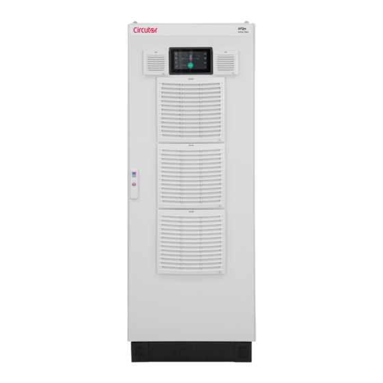
Page 9: 2�- Product Description
Correct the power factor. For both backward (inductive) and forward (capacitive) currents. The AFQm IP54 has a cabinet-type enclosure with reinforced protection to keep out dust and water, which allows the device to be safely installed in dusty places or where it may be reached by splashing water. - Page 10 AFQm IP54 Table 3 (Continuation): Relation of models AFQm IP54� 3 Wires 4 Wires Mains voltage Model Current ( L1, L2, L3) ( L1, L2, L3, N) (Un) AFQm-4WF-280C-550 280 A 230 ... 550 V AFQm-3WF-300C-480 300 A 208 ... 480 V ...
-
Page 11: 3�- Device Installation
AFQm IP54 3.- DEVICE INSTALLATION 3�1�- PRELIMINARY RECOMMENDATIONS The device installation and the maintenance operations must only be carried out by authorised and qualified personnel� In order to use the device safely, it is critical that individuals who handle it follow the... -
Page 12: 3�2�- Installation Location
“4.6 - THERMAL PROTECTION” The AFQm IP54 uses a cooling system with an air inlet at the front and an air outlet at the rear of the unit. Be sure to leave a gap at the back of the cabinet of at least 150 mm. To ensure this, the device includes spacers at the rear that act as a bumper. -
Page 13: 3�3�- Storage For Long Periods
STOP mode 3�4�- INSTALLATION The Cabinet-type AFQm IP54 models are free-standing cabinets with 4 bearing supports on the floor. The mounting surface must be solid, support the device’s weight and be level. The cabinet must never be welded to the floor using arc welding, as this may destroy the electronic components. -
Page 14: 3�5�- Connection
These sections are for informative purposes only. The conductor cross-section must be selected according to the current, prevailing regulations, cable type and type of wiring installation. Ensure that the AFQm IP54 is earthed correctly to prevent the risk of electric shock. To measure the current, class 0�2S transformers of the TC or TCH series are recom- mended. -
Page 15: 3�6�- Device Terminals
Figure 4: Do not install various active filters in series� 3�6�- DEVICE TERMINALS The connections on the AFQm IP54 are located at the bottom of the cabinet. The lower windows on the cabinet have to be used to route the cables into the device,... - Page 16 The green lights on the surge voltage protection indicate that they are working cor- rectly. Immediately replace those whose indicator is red, see “10.2.- MAINTENANCE OF SURGE PROTECTIVE DEVICES:70A, 140A, 210A AND 280A AFQm IP54” Once the front cover is open, the device’s terminals can be accessed, Figure 7 Figure 8 Figure 7: AFQm IP54 terminals�...
- Page 17 AFQm IP54 Figure 8: AFQm IP54 earth terminal� Table 6: List of terminals� Device terminals 1: S1, Current input L1 6: S2, Current input L3 2: S2, Current inpu 7: L1, Mains connection L1 3: S1, Current input L2 8: L2, Mains connection L2...
- Page 18 2: IN, Input for parallel connection 3: OUT, Output for parallel connection The terminals of the RS-485 and Ethernet communications ports are located at the back of the front screen on the AFQm IP54, see Figure 10� Figure 10: Terminals of the communication ports�...
-
Page 19: 3�7�- Connection Diagrams
AFQm IP54 3�7�- CONNECTION DIAGRAMS 3�7�1�- 4-WIRE CONNECTION AND CURRENT MEASUREMENT ON THE MAINS SIDE� RED/ MAINS P2 S1 P2 S1 CARGA / LOAD Figure 11: Three-phase measuring with 4-wire connection and current measurement on the mains side� Use the 2 neutral current terminals, as In can be:In ≈ 3 * I... -
Page 20: 3�7�2�- 4-Wire Connection And Current Measurement On The Load Side
AFQm IP54 3�7�2�- 4-WIRE CONNECTION AND CURRENT MEASUREMENT ON THE LOAD SIDE� RED/ MAINS CARGA / LOAD P2 S1 P2 S1 Figure 12: Three-phase measuring with 4-wire connection and current measurement on the load side� Use the 2 neutral current terminals, as In can be: In ≈ 3 * I... -
Page 21: 3�7�3�- 3-Wire Connection And Current Measurement On The Mains Side
AFQm IP54 3�7�3�- 3-WIRE CONNECTION AND CURRENT MEASUREMENT ON THE MAINS SIDE� CARGA / LOAD RED/ MAINS P2 S1 P2 S1 Figure 13: Three-phase measuring with 3-wire connection and current measurement on the mains side� Instruction Manual... -
Page 22: 3�7�4�- 3-Wire Connection And Current Measurement On The Load Side
AFQm IP54 3�7�4�- 3-WIRE CONNECTION AND CURRENT MEASUREMENT ON THE LOAD SIDE� CARGA / LOAD RED/ MAINS P2 S1 P2 S1 Figure 14: Three-phase measuring with 3-wire connection and current measurement on the load side� Instruction Manual... -
Page 23: 3�7�5�- 3-Wire Connection And 2 Current Transformers On The Mains Side
AFQm IP54 3�7�5�- 3-WIRE CONNECTION AND 2 CURRENT TRANSFORMERS ON THE MAINS SIDE� RED/ MAINS CARGA / LOAD Figure 15: Three-phase measuring with a 3-wire connection and 2 current transformers on the mains side� The connection of 2 current transformers is only possible in three-phase mains without neutral (3 wires). -
Page 24: 3�7�6�- 3-Wire Connection And 2 Current Transformers On The Load Side
AFQm IP54 3�7�6�- 3-WIRE CONNECTION AND 2 CURRENT TRANSFORMERS ON THE LOAD SIDE� RED/ MAINS CARGA / LOAD Figure 16: Three-phase measuring with a 3-wire connection and 2 current transformers on the load side� The connection of 2 current transformers is only possible in three-phase mains without neutral (3 wires). -
Page 25: 3�8�- Parallel Connection Of 2 To 100 Active Filters
AFQm IP54 3�8�- PARALLEL CONNECTION OF 2 TO 100 ACTIVE FILTERS The AFQm IP54 devices can be arranged in parallel to increase the available filtering power. Expandable by up to 100 parallel devices of the 70A and 100A models. In the case of installations with devices in parallel, a device must be defined as the “master”, while all others will have “slave”... - Page 26 Slave (*) Connections already included in the cabinets AFQm-xxx-200C Figure 19: Connecting 3 devices in parallel, using the communication cable (200 A Master AFQm IP54)� 5�- Configure the installation in the “master” device (see “7.- CONFIGURATION” 6�- Complete the configuration of the slave devices (see “7.- CONFIGURATION”).
-
Page 27: 4�- Operation
AFQm IP54 4.- OPERATION 4�1�- HARMONICS Non-linear loads such as: rectifiers, inverters, variable speed drives, ovens, etc., absorb periodic non sine-wave currents from the mains. These currents are composed of a fundamental frequency component, rated at 50 or 60 Hz, plus a series of overlapping currents, with frequencies that are multiples of the fundamental frequency;... -
Page 28: 4�1�2�- Most Common Harmonics
�������� �������� ∗ 100 �������� �������� �������� �������� AFQm IP54 �������� ∗ 100 �������� �������� �������� ���� ���� ∗ 100 ���� Individual distortion rate (U % or I %): A ratio in % between the RMS value of the voltage or ����... -
Page 29: 4�1�3�- Harmonic Compensation
AFQm IP54 Table 11: Most common harmonics� Harmonic spectrum Type of load Wave shape THD(I) 6-pulse converters Variable speed drives Three-phase rectifiers Converters for electrolysis and baths Discharge lamps Single-phase converters Lighting lines Computer lines Sound and image devices 4�1�3�- HARMONIC COMPENSATION Active filters are devices responsible for the compensation of harmonic currents. -
Page 30: 4�2�- Operating Principle
The purchased active filter must be sized for the harmonic currents it has to filter. The rated current of the AFQm IP54 must be at least 20% higher than the maximum level of harmonics to be filtered. This factor may be higher depending on the installation features. - Page 31 ���� = ����� + ���� + ���� + ���� + ⋯ AFQm IP54 ����� + ���� + ���� + ⋯ To avoid this phenomenon, it is best to oversize the active filter by multiplying the initial current of ������������ ( ���� ) % = ����...
-
Page 32: 4�4�- Resonance Detection
In certain cases, there may be a load that provides less impedance than the mains, in which case a resonance phenomenon will be produced with that load. The AFQm IP54 has a detection system for resonance with loads, which automatically deactivates the harmonic that causes that resonance. -
Page 33: 4�6�- Thermal Protection
AFQm IP54 4�6�- THERMAL PROTECTION The device features several levels of thermal protection: Ventilation regulation, the fan speed is adjusted as needed at any given time, thus minimising the noise in the device. Static temperature limitation, the device reduces its power if the internal temperature exceeds certain limits. -
Page 34: 4�7�1�- Central Area
AFQm IP54 The display is divided into two areas ( Figure 26 Central area Side areas Figure 26: The display is divided into three areas� 4�7�1�- CENTRAL AREA The central area shows the following: The condition of the installation, ... - Page 35 AFQm IP54 To access the generic information screens, see “6.6 - GENERIC INFORMATION SCREENS” symbol means the device has advice pending that needs to be read. The device continuously analyses its behaviour and interaction with the installation. This analysis enables it to give advice on how to optimise overall system performance.
-
Page 36: 5�- Start
AFQm IP54 5.- START-UP When the device has been powered the screen in appear on the display. Figure 27 Figure 27: Home screen� Before starting the active filter, it is necessary to follow the steps below: 1�- Go into the configuration screens, and set up the device as required for the existing installa- tion.(See... -
Page 37: 6�- Display
In the lower left part of the screen, a message with the current status of the device is shown ( Table 13 Table 13: Status messages Status messages Starting Description The AFQm IP54 is starting up. Init Description The device is starting the systems. Waiting comms Description... -
Page 38: 6�1�2� - Device Slave
Status messages Configuration Description Configuring the device. Description Device is operating. Sync Description The AFQm IP54 is synchronising with the mains. Charging Bus DC Description Charging process of the internal bus prior to start-up. Stop Description Device stopped. Alarm An alarm has been generated. -
Page 39: 6�2�- Numeric Values Screens
AFQm IP54 6�2�- NUMERIC VALUES SCREENS To access the numeric value screens, click on Note: Swipe right or left to scroll through the different screens. Note: These screens are not visible on “slave” devices. 6�2�1�- THD Figure 30: THD display�... -
Page 40: 6�2�3�- Harmonic Current
AFQm IP54 6�2�3�- HARMONIC CURRENT displays the harmonic current in absolute value for each of the mains and load phases. Figure 32 Figure 32: Harmonic current� 6�2�4�- TABLE OF HARMONICS In this screen, , shows all the voltage harmonics, load current and mains current in table form Figure 33 for each phase. -
Page 41: 6�2�5�- Voltage / Current / Frequency
AFQm IP54 6�2�5�- VOLTAGE / CURRENT / FREQUENCY shows the Voltage, Current and Frequency screen. Figure 34 Figure 34: Voltage, Current and Frequency display� It shows: The Voltage in each of the phases, L1, L2 and L3. The Current in the Mains in each of the phases, L1, L2, L3 and Neutral. -
Page 42: 6�2�7�- Power And Cos ɸ Of Load
AFQm IP54 6�2�7�- POWER AND COS ɸ OF LOAD shows the power and cos ɸ of the load. Figure 36 Figure 36: Display of the power and cos ɸ of the load� It shows: The Active Power (P), Reactive Power (Q) and Apparent Power (S). -
Page 43: 6�3�2�- Mains Phasors
AFQm IP54 6�3�2�- MAINS PHASORS In this screen, , the mains phasors are shown. Figure 38 Figure 38: Mains phasors� 6�4�- HARMONICS SCREENS To access the harmonics screens, click on Note: Swipe right or left to scroll through the different screens. -
Page 44: 6�4�2�- Current Harmonics (Load)
AFQm IP54 6�4�2�- CURRENT HARMONICS (LOAD) In this screen, , the odd harmonics of the Load from 3 to 25 are shown for each of the phases. Figure 40 Figure 40: Display of the Load harmonics� 6�4�3�- CURRENT HARMONICS (MAINS) In this screen, , the odd harmonics of the Mains, from 3 to 25, are shown for each of the phases. -
Page 45: 6�5�- Waveform Screens
AFQm IP54 6�5�- WAVEFORM SCREENS To access the waveform screens, click on Note: Swipe right or left to scroll through the different screens. Note: These screens are not visible on “slave” devices. 6�5�1�- VOLTAGE WAVEFORM This screen, , shows the voltage waveform for each phase. -
Page 46: 6�5�3�- Wave Shape Of Main Current
AFQm IP54 6�5�3�- WAVE SHAPE OF MAIN CURRENT In this screen, , the wave shape of the mains current is shown for each of the phases. Figure 44 Figure 44: Wave shape of mains current� 6�6�- GENERIC INFORMATION SCREENS To access the generic information screens, click on Note: Swipe right or left to scroll through the different screens. -
Page 47: 6�6�2�- Ethernet Communications
AFQm IP54 6�6�2�- ETHERNET COMMUNICATIONS In this screen, , the IP address of the device and the netmask are shown. Figure 46 Figure 46: Communications� 6�6�3�- DEVICE INFORMATION In this screen, , the serial number, HMI and DSP versions of the device are shown. -
Page 48: 6�6�4�- Manufacturer Information
AFQm IP54 6�6�4�- MANUFACTURER INFORMATION This screen, , shows information on CIRCUTOR. Figure 48 Figure 48: Manufacturer information� 6�7�- ALARM AND WARNING SCREENS To access the alarm and warning screens, click on Note: Swipe right or left to scroll through the different screens. - Page 49 Table 14: Alarm messages� Alarm messages Overcurrent L1/L2/L3 Description The AFQm IP54 current is too high. Corrective This alarm may be associated with transients and noise in the power supply voltage. Check the quality action of the power supply voltage. If it continues, contact the TAS.
-
Page 50: 6�7�2�- Warnings
AFQm IP54 Table 14 (Cont�): Alarm messages� Alarm messages Initial Conditions Description The start-up conditions have not been met 10 times during the past 5 minutes. Corrective Check the configuration and the ambient temperature. Check the quality of the power supply voltage. - Page 51 AFQm IP54 Figure 52: Warnings� Table 15: Warnings messages� Warnings messages Waiting for conditions Description The start-up conditions are not met. Corrective Check the alert messages. action Load polarity Description Detection of an error in the load polarity. Corrective Check the transformer connections. See section “7.9.- TRANSFORMER CONFIGURATION”...
- Page 52 AFQm IP54 Table 15 (Cont�): Warnings messages� Alarm and event messages Corrective Wait for the environmental conditions to meet the requirements. If the alarm continues, contact the action TAS� Mains frequency limits Description Main frequency out of the limits This alert may be associated with transients and noise in the power supply voltage, or with incorrect Corrective mains frequency values.
-
Page 53: 7�- Configuration
AFQm IP54 7.- CONFIGURATION To access the configuration screens, click on Note: Swipe right or left to scroll through the different screens. shows the initial configuration screen. Figure 53 Figure 53: Initial configuration screen� Initially, the configuration screens are in display mode, meaning all device parameters are shown but cannot be edited. -
Page 54: 7�1�- Language
AFQm IP54 7�1�- LANGUAGE In this screen, , the language of the display is selected. Figure 55 Figure 55: Configuration screen: Language� ● Language, display language. Press the key to save the modified settings. 7�2�- DEVICE SPECIFICATIONS Note: This screen is informative, it can not be modified. -
Page 55: 7�3�- Installed Devices
In this screen the type of device is selected, the possible options are: Single: select this option if the AFQm IP54 does not have filters connected in parallel. Master: select this option if the filter is going to be used as the “master” of a group of devices in parallel. -
Page 56: 7�4�- Working Mode
AFQm IP54 7�4�- WORKING MODE Note: This screen is not visible on the “slave” devices. In this screen, , the following parameters of the device’s operating mode are configured: Figure 58 Figure 58: Configuration screen: Operation mode� ● Mode In this parameter, the control algorithm that the device will use for harmonic filtering is selected, the options are: ... - Page 57 AFQm IP54 The phase balancing option in AFQm-3WF-xxxx works in unbalances produced by loads connected between phases in three-phase mains without neutral. The AFQm-3WF-xxxx does not compensate unbalances produced by single-phase loads connected between phase and neutral. Use a AFQm-4WF-xxxx to correct this type of unbalances.
-
Page 58: 7�5�- Harmonics Selection
The minimum load current to start the active filter is configured with this parameter. Minimum current feature is used to increase the system efficiency, by stopping the filter when required. The AFQm IP54 will stop when the load current is below the entered value and will start when it is higher. -
Page 59: 7�7�- Cos
AFQm IP54 Range of values: Minimum value: 0 A Maximum value: 5000 A ● Current limit This parameter allows the maximum power of the active filter to be limited. The value is configured as a percentage with respect to the device’s rated power. -
Page 60: 7�8�- Ieee519
AFQm IP54 reducing its energy consumption. Range of values: 0.7... -0.7 Press the key to save the modified settings. 7�8�- IEEE519 Note: This screen is not visible on the “slave” devices. This screen, , may be configured if the device is to comply with the filtering limits specified in... - Page 61 AFQm IP54 The first two parameters may be obtained from the rating plate on the network connection transformer. If this function is enabled, the device will only correct the harmonics to meet the requirements of the established limits, instead of trying to cancel the harmonics altogether.
-
Page 62: 7�9�- Transformer Configuration
The location of the transformers is configured with this parameter, the options are: LOAD: If the transformers are installed in the load area, downstream from the AFQm IP54. MAINS: If the transformers are installed in the mains area, upstream from the AFQm IP54. -
Page 63: 7�10�- Alarms
AFQm IP54 ● Invert This parameter is used to select the phase whose filter is going to switch the current direction of the load measurement transformer, so installation faults may be corrected. Press the key to save the modified settings. -
Page 64: 7�11�- Ethernet Communications
7�12�- RS-485 COMMUNICATIONS The RS-485 communications configuration in AFQm IP54 models is set to a Baud rate of 9600 bps, 8 data bits, 1 stop bit and no parity. Only the device’s Modbus address can be configured, Figure 66 Figure 66: Configuration screen: RS-485 communications�... -
Page 65: 7�13�- Date / Time
AFQm IP54 7�13�- DATE / TIME The time parameters are configured in this screen, Figure 67 Figure 67: Configuration screen: Date / Time ● Time. ● Date. ● Time zone. By activating the Internet time option, the device synchronises with the time of the Web server to which it is connected. - Page 66 AFQm IP54 ● Stop Password. key may be configured with a password; if enabled, the device will request the password on being pressed and will not stop unless the correct password is entered. Press the key to save the modified settings.
-
Page 67: 8�- Rs-485 Communications
RS-232 Ethernet Profibus RS-485 RS-485 B(-) A(+) Figure 69: RS-485 Connection diagram� The RS-485 communications configuration in AFQm IP54 models is set to a baud rate of 9600 bps, 8 data bits, 1 stop bit and no parity. Instruction Manual... -
Page 68: 8�2�- Protocol
AFQm IP54 8�2�- PROTOCOL In the Modbus protocol, the AFQm IP54 uses the RTU (Remote Terminal Unit) mode. The Modbus functions implemented in the device are as follows: Functions 03 and 04: Reading of n Words (2 bytes). 8�2�1�- EXAMPLE OF MODBUS QUERY... - Page 69 AFQm IP54 Table 18: Modbus memory map: Measurements with Load (Table 2)� Parameter Current L1 Current L2 Current L3 Units Fundamental harmonic 3rd order harmonic 5th order harmonic 7th order harmonic 9th order harmonic 11th order harmonic 13th order harmonic...
- Page 70 Table 24: Modbus memory map: Measurements in the Mains (Table 4)� Parameter Units Fundamental current Harmonic current 8�2�2�3�- Other parameters of the AFQm IP54 filter Table 25: Modbus memory map: Filter parameters (Table 1)� Parameter Address Units Temperature IGBT 1 ºC with 1 decimal...
- Page 71 DSP software version HMI software version For a system with devices in parallel, the parameter value is that of the device connected with RS-485. 8�2�2�4�- AFQm IP54 filter messages Table 28: Modbus memory map: Filter messages (Table 1)� Parameter Address...
- Page 72 For a system with devices in parallel, the parameter value is that of the device connected with RS-485. Table 31: Modbus memory map: Filter messages (Table 4)� Parameter Address AFQm IP54 status Status (Decimal value) Description Start-up 10, 20, 30...
- Page 73 AFQm IP54 Table 32: Modbus memory map: Filter messages (Table 5)� Parameter Address Harmonics status Description Status 0x0001 Harmonic 3 0x0002 Harmonic 5 0x0004 Harmonic 7 0x0008 Harmonic 9 0x0010 Harmonic 11 1: Harmonic filtering 0x0020 Harmonic 13 0: Harmonic disabled due...
-
Page 74: 9�- Ethernet Communications
For an installation with devices in parallel, the Ethernet connection can be made on any device. 9�1�- CONNECTION The AFQm IP54 has an Ethernet port. This type of communication creates an intranet with IP commu- nications. To monitor the device remotely, the Ethernet communications cable must be connected to the front... - Page 75 AFQm IP54 The language of the web site can be modified using the buttons that appear on the upper right part of the page. To modify the Configuration parameters, it is necessary to enter the User and Password in the Admin- istrator section.
-
Page 76: 10�- Maintenance
AFQm IP54 10.- MAINTENANCE The AFQm IP54 active filter requires minimum preventive maintenance. It is recommended to follow the notes described in this chapter to avoid premature damage to the device's components. shows the maintenance jobs with their respective time intervals. -
Page 77: 10�1�- Filter Media
If the excess dirt in the filter media significantly affects the operation of the device, the AFQm IP54 will display an alarm per screen. This will happen when the air flow is so reduced that the device cannot exceed 50% of its operating capacity. -
Page 78: 10�2�- Maintenance Of Surge Protective Devices: 70A, 140A, 210A And 280A Afqm Ip54
AFQm IP54 10�2�- MAINTENANCE OF SURGE PROTECTIVE DEVICES: 70A, 140A, 210A AND 280A AFQm IP54 The device has removable surge protective that are accessible from the front. They feature a green indicator to signal the correct operation of the protective. -
Page 79: 11�- Technical Features
AFQm IP54 11.- TECHNICAL FEATURES Mains voltage AFQm-3WF-xxxx-480 AFQm-4WF-xxxx-400 208 ... 480 Vac ± 10% 208 ... 400 Vac ± 10% Ph-Ph Ph-Ph Rated voltage Un AFQm-3WF-xxxx-690 AFQm-4WF-xxxx-550 230 ... 690 V~ ± 10% 230 ... 550 V~ ± 10%... - Page 80 AFQm IP54 AFQm-xxx-070C AFQm-xxx-140C Rated insulation voltage Ui 690 V 690 V Impulse withstand voltage Uimp 6kV, CAT III Class 1 6kV, CAT III Class 1 Rated current (phase) I 70 A 140 A na phase Rated current (neutral) I...
- Page 81 AFQm IP54 Filter specifications Filtering 2 ... 50 harmonic (adjustable) Response time < 100 μs Phase compensation Adjustable Power factor correction Adjustable Programming of priorities Adjustable Up to 100 devices of different calibres Parallel connection Connection of the transformers only in the Master device...
- Page 82 AFQm IP54 (Cont�) Environmental features Impact resistance IK 10 Electromagnetic compatibility Installation in type-A environments Standards Electromagnetic compatibility (CEM)� Part 6-4: Generic standards� Emissions stand- UNE-EN 61000-6-4:2007 ard for industrial environments� (IEC 61000-6-4:2006)� Industrial, scientific and medical equipment - Radio-frequency disturbance charac-...
- Page 83 , the earth conductor can be the half of the cross-section of the phase conductors. (10) The connection bars allow the cables to be placed on both sides, and two cables may be routed through each drill hole. Figure 75: Dimensions AFQm IP54� Instruction Manual...
-
Page 84: 12�- Technical Service
AFQm IP54 12.- TECHNICAL SERVICE In the case of any query in relation to device operation or malfunction, please contact the CIRCUTOR, SA Technical Support Service. Technical Assistance Service Vial Sant Jordi, s/n, 08232 - Viladecavalls (Barcelona) Tel: 902 449 459 ( España) / +34 937 452 919 (outside of Spain) email: sat@circutor.com... -
Page 85: 14�- Ce Certificate
AFQm IP54 14.- CE CERTIFICATE Instruction Manual... - Page 86 AFQm IP54 Instruction Manual...
- Page 87 AFQm IP54 Instruction Manual...
- Page 88 CIRCUTOR, SA Vial Sant Jordi, s/n 08232 - Viladecavalls (Barcelona) Tel: (+34) 93 745 29 00 - Fax: (+34) 93 745 29 14 www.circutor.es central@circutor.com...
Need help?
Do you have a question about the AFQm IP54 and is the answer not in the manual?
Questions and answers