Table of Contents
Advertisement
Quick Links
Advertisement
Table of Contents

Related Manuals for Circutor SVGm IP54


Summary of Contents for Circutor SVGm IP54
- Page 1 Static var generator SVGm IP54 INSTRUCTION MANUAL (M322B01-03-21A)
- Page 2 SVGm IP54 Instruction Manual...
-
Page 3: Safety Precautions
CIRCUTOR, SA reserves the right to make modifications to the device or the unit specifications set out in this instruction manual without prior notice. CIRCUTOR, SA on its web site, supplies its customers with the latest versions of the device specifica- tions and the most updated manuals. -
Page 4: Table Of Contents
SVGm IP54 CONTENTS SAFETY PRECAUTIONS ���������������������������������������������������������������������������������������������������������������������������������������������������������3 DISCLAIMER ��������������������������������������������������������������������������������������������������������������������������������������������������������������������������3 CONTENTS �����������������������������������������������������������������������������������������������������������������������������������������������������������������������������4 REVISION LOG �����������������������������������������������������������������������������������������������������������������������������������������������������������������������6 SYMBOLS �������������������������������������������������������������������������������������������������������������������������������������������������������������������������������6 1�- VERIFICATION UPON RECEPTION ������������������������������������������������������������������������������������������������������������������������������������ 7 1�1�- RECEPTION PROTOCOL ��������������������������������������������������������������������������������������������������������������������������������������������� 7 1�2�- TRANSPORT AND HANDLING ����������������������������������������������������������������������������������������������������������������������������������� 7 1�3�- STORAGE ������������������������������������������������������������������������������������������������������������������������������������������������������������������8 2�- PRODUCT DESCRIPTION �������������������������������������������������������������������������������������������������������������������������������������������������9 3�- DEVICE INSTALLATION ���������������������������������������������������������������������������������������������������������������������������������������������������11 3�1�- PRELIMINARY RECOMMENDATIONS �����������������������������������������������������������������������������������������������������������������������11... - Page 5 SVGm IP54 7�1�- LANGUAGE �������������������������������������������������������������������������������������������������������������������������������������������������������������� 47 7�2�- DEVICE SPECIFICATIONS ���������������������������������������������������������������������������������������������������������������������������������������� 47 7�3�- INSTALLED DEVICES ����������������������������������������������������������������������������������������������������������������������������������������������48 7�4�- OPERATING LIMITS ������������������������������������������������������������������������������������������������������������������������������������������������49 7�5�- cos Φ ���������������������������������������������������������������������������������������������������������������������������������������������������������������������50 7�6�- TRANSFORMER CONFIGURATION �������������������������������������������������������������������������������������������������������������������������� 51 7�7�- MEDIUM VOLTAGE ��������������������������������������������������������������������������������������������������������������������������������������������������52 7�8�- ETHERNET COMMUNICATIONS ������������������������������������������������������������������������������������������������������������������������������53 7�9�- RS-485 COMMUNICATIONS ����������������������������������������������������������������������������������������������������������������������������������53 7�10�- DATE / TIME ����������������������������������������������������������������������������������������������������������������������������������������������������������54...
-
Page 6: Revision Log
SVGm IP54 REVISION LOG Table 1: Revision log� Date Revision Description 03/21 M322B01-03-21A Initial Version SYMBOLS Table 2: Symbols� Symbol Description Compliant with the relevant European standards. After disconnecting the device from all power supplies, wait 1 minute before per- forming any operations. -
Page 7: 1�- Verification Upon Reception
Perform an external and internal visual inspection of the device prior to connecting it. If any problem is noticed upon reception, immediately contact the transport com- pany and/or CIRCUTOR's after-sales service. 1�2�- TRANSPORT AND HANDLING The transport, loading and unloading and handling of the device must be carried out with proper precautions and using the proper manual and mechanical tools so as not to damage it. -
Page 8: 1�3�- Storage
The SVGm IP54 devices cabinet type, there are also 4 rings (diameter : 28 mm) in the top panel so that they can be transported by a crane. The top panel is inverted, but the rings are mounted, to enable it to be transported without any prior set-up required. -
Page 9: 2�- Product Description
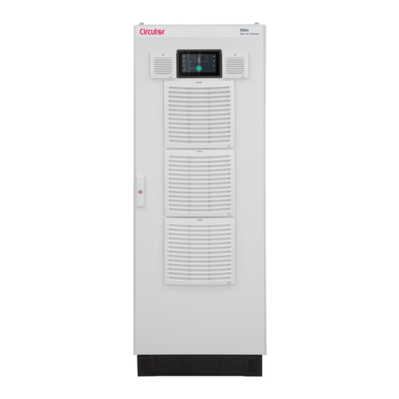
SVGm IP54 2.- PRODUCT DESCRIPTION The SVGm IP54 static var generator can be used to correct the power factor. For both backward (induc- tive) and forward (capacitive) currents. The AFQm IP54 has a cabinet-type enclosure with reinforced protection to keep out dust and water, which allows the device to be safely installed in dusty places or where it may be reached by splashing water. - Page 10 SVGm IP54 Table 3 (Continuation): Relation of models SVGm IP54� 3 Wires 4 Wires Power Mains voltage Model ( L1, L2, L3) ( L1, L2, L3, N) (kvar) (Un) SVGm-3WF-300C-480 208 ... 480 V SVGm-3WF-300C-690 230 ... 690 V ...
-
Page 11: 3�- Device Installation
SVGm IP54 3.- DEVICE INSTALLATION 3�1�- PRELIMINARY RECOMMENDATIONS The device installation and the maintenance operations must only be carried out by authorised and qualified personnel� In order to use the device safely, it is critical that individuals who handle it follow the... -
Page 12: 3�2�- Installation Location
“4.6 - THERMAL PROTECTION” The SVGm IP54 uses a cooling system with an air inlet at the front and an air outlet at the rear of the unit. Be sure to leave a gap at the back of the cabinet of at least 150 mm. To ensure this, the device includes spacers at the rear that act as a bumper. -
Page 13: 3�3�- Storage For Long Periods
STOP mode 3�4�- INSTALLATION The Cabinet-type SVGm IP54 models are free-standing cabinets with 4 bearing supports on the floor. The mounting surface must be solid, support the device’s weight and be level. The cabinet must never be welded to the floor using arc welding, as this may destroy the electronic components. -
Page 14: 3�5�- Connection
These sections are for informative purposes only. The conductor cross-section must be selected according to the current, prevailing regulations, cable type and type of wiring installation. Ensure that the SVGm IP54 is earthed correctly to prevent the risk of electric shock. To measure the current, class 0�2S transformers of the TC or TCH series are recom- mended. -
Page 15: 3�6�- Device Terminals
Figure 4: Do not install various static generators in series� 3�6�- DEVICE TERMINALS The connections on the SVGm IP54 are located at the bottom of the cabinet. The lower windows on the cabinet have to be used to route the cables into the device,... - Page 16 Immediately replace those whose indicator is red, see “10.2.- MAINTENANCE OF SURGE PROTECTIVE DEVICES: SVGm-3WF-xxxC-690 and SVGm-4WF-xxxC-550” Once the front cover is open, the device’s terminals can be accessed, Figure 7 Figure 8 Figure 7: SVGm IP54 terminals� Instruction Manual...
- Page 17 SVGm IP54 Figure 8: SVGm IP54 earth terminal� Table 6: List of terminals� Device terminals 1: S1, Current input L1 6: S2, Current input L3 2: S2, Current inpu 7: L1, Mains connection L1 3: S1, Current input L2 8: L2, Mains connection L2...
- Page 18 2: IN, Input for parallel connection 3: OUT, Output for parallel connection The terminals of the RS-485 and Ethernet communications ports are located at the back of the front screen on the SVGm IP54, see Figure 10� Figure 10: Terminals of the communication ports�...
-
Page 19: 3�7�- Connection Diagrams
SVGm IP54 3�7�- CONNECTION DIAGRAMS 3�7�1�- 4-WIRE CONNECTION AND CURRENT MEASUREMENT ON THE MAINS SIDE� RED/ MAINS P2 S1 P2 S1 CARGA / LOAD Figure 11: Three-phase measuring with 4-wire connection and current measurement on the mains side� Use the 2 neutral current terminals, as In can be:In ≈ 3 * I... -
Page 20: 3�7�2�- 4-Wire Connection And Current Measurement On The Load Side
SVGm IP54 3�7�2�- 4-WIRE CONNECTION AND CURRENT MEASUREMENT ON THE LOAD SIDE� RED/ MAINS CARGA / LOAD P2 S1 P2 S1 Figure 12: Three-phase measuring with 4-wire connection and current measurement on the load side� Use the 2 neutral current terminals, as In can be: In ≈ 3 * I... -
Page 21: 3�7�3�- 3-Wire Connection And Current Measurement On The Mains Side
SVGm IP54 3�7�3�- 3-WIRE CONNECTION AND CURRENT MEASUREMENT ON THE MAINS SIDE� CARGA / LOAD RED/ MAINS P2 S1 P2 S1 Figure 13: Three-phase measuring with 3-wire connection and current measurement on the mains side� Instruction Manual... -
Page 22: 3�7�4�- 3-Wire Connection And Current Measurement On The Load Side
SVGm IP54 3�7�4�- 3-WIRE CONNECTION AND CURRENT MEASUREMENT ON THE LOAD SIDE� CARGA / LOAD RED/ MAINS P2 S1 P2 S1 Figure 14: Three-phase measuring with 3-wire connection and current measurement on the load side� Instruction Manual... -
Page 23: 3�7�5�- 3-Wire Connection And 2 Current Transformers On The Mains Side
SVGm IP54 3�7�5�- 3-WIRE CONNECTION AND 2 CURRENT TRANSFORMERS ON THE MAINS SIDE� RED/ MAINS CARGA / LOAD Figure 15: Three-phase measuring with a 3-wire connection and 2 current transformers on the mains side� The connection of 2 current transformers is only possible in three-phase mains without neutral (3 wires). -
Page 24: 3�7�6�- 3-Wire Connection And 2 Current Transformers On The Load Side
SVGm IP54 3�7�6�- 3-WIRE CONNECTION AND 2 CURRENT TRANSFORMERS ON THE LOAD SIDE� RED/ MAINS CARGA / LOAD Figure 16: Three-phase measuring with a 3-wire connection and 2 current transformers on the load side� The connection of 2 current transformers is only possible in three-phase mains without neutral (3 wires). -
Page 25: 3�8�- Parallel Connection Of 2 To 100 Svgm
SVGm IP54 3�8�- PARALLEL CONNECTION OF 2 TO 100 SVGm The SVGm IP54 devices can be arranged in parallel. Expandable by up to 100 parallel devices of the 67 kvar, 69 kvar and 100 kvar models. In the case of installations with devices in parallel, a device must be defined as the “master”, while all others will have “slave”... - Page 26 Slave (*) Connections already included in the cabinets SVGm-xxx-200C Figure 19: Connecting 3 devices in parallel, using the communication cable (200 A Master SVGm IP54)� 5�- Configure the installation in the “master” device (see “7.- CONFIGURATION” 6�- Complete the configuration of the slave devices (see “7.- CONFIGURATION”).
-
Page 27: 4�- Operation
SVGm IP54 4.- OPERATION 4�1�- OPERATING PRINCIPLE The currents consumed by the loads present in any installation have two components: an active com- ponent, which generates an effort, and a reactive component, generated by the inductive or capacitive nature of the load. -
Page 28: 4�2�- Medium Voltage
SVGm IP54 be used in distorted networks, with no need to add filtering elements to the installation. 4�2�- MEDIUM VOLTAGE The SVGm is able to compensate for the reactive current in medium voltage with the unit connected in low voltage. To do this, a current measurement transformer must be used to measure the medium voltage current. -
Page 29: 4�5�- Display
SVGm IP54 Dynamic limitation of the device, one of the factors affecting the reliability of the device is the stress caused by repeated heating and cooling cycles. The device adjusts both its ventilation and power to minimise the impact that thermal cycling has on the life of the device. -
Page 30: 4�5�1�- Central Area
SVGm IP54 Central area Side areas Figure 24: The display is divided into three areas� 4�5�1�- CENTRAL AREA The central area shows the following: The condition of the installation, All parameters and graphs of the device. And the necessary keys at each point, Table 10 Table 10: Central area keys�... - Page 31 SVGm IP54 analyses its behaviour and interaction with the installation. This analysis enables it to give advice on how to optimise overall system performance. Once the icon has been read, it disappears until further advice is offered. To access the alarm and warning screens, see “6.6 - ALARM AND WARNING SCREENS”.
-
Page 32: 5�- Start
SVGm IP54 5.- START-UP When the device has been powered the screen in appear on the display. Figure 25 Figure 25: Home screen� Before starting the static generator, it is necessary to follow the steps below: 1�- Go into the configuration screens, and set up the device as required for the existing installa- tion.(See... -
Page 33: 6�- Display
In the lower left part of the screen, a message with the current status of the device is shown ( Table 11 Table 11: Status messages Status messages Starting Description The SVGm IP54 is starting up. Init Description The device is starting the systems. Waiting comms Description... -
Page 34: 6�1�2� - Device Slave
Status messages Configuration Description Configuring the device. Description Device is operating. Sync Description The SVGm IP54 is synchronising with the mains. Charging Bus DC Description Charging process of the internal bus prior to start-up. Stop Description Device stopped. Alarm An alarm has been generated. -
Page 35: 6�2�- Numeric Values Screens
SVGm IP54 6�2�- NUMERIC VALUES SCREENS To access the numeric value screens, click on Note: Swipe right or left to scroll through the different screens. Note: These screens are not visible on “slave” devices. 6�2�1�- VOLTAGE / CURRENT / FREQUENCY shows the Voltage, Current and Frequency screen. -
Page 36: 6�2�3�- Power And Cos ɸ Of Load
SVGm IP54 The Active Power (P), Reactive Power (Q) and Apparent Power (S). The cos ɸ Note: The - sign in reactive power indicates that it is capacitive and the + sign that it is inductive. 6�2�3�- POWER AND COS ɸ OF LOAD shows the power and cos ɸ... -
Page 37: 6�3�- Phasor Screens
SVGm IP54 6�3�- PHASOR SCREENS To access the phasor screens, click on Note: Swipe right or left to scroll through the different screens. Note: These screens are not visible on “slave” devices. 6�3�1�- LOAD PHASORS In this screen, , the load phasors are shown. -
Page 38: 6�4�- Waveform Screens
SVGm IP54 6�4�- WAVEFORM SCREENS To access the waveform screens, click on Note: Swipe right or left to scroll through the different screens. Note: These screens are not visible on “slave” devices. 6�4�1�- VOLTAGE WAVEFORM This screen, , shows the voltage waveform for each phase. -
Page 39: 6�4�3�- Wave Shape Of Main Current
SVGm IP54 6�4�3�- WAVE SHAPE OF MAIN CURRENT In this screen, , the wave shape of the mains current is shown for each of the phases. Figure 35 Figure 35: Wave shape of mains current� 6�5�- GENERIC INFORMATION SCREENS To access the generic information screens, click on Note: Swipe right or left to scroll through the different screens. -
Page 40: 6�5�2�- Ethernet Communications
In this screen, , the serial number, HMI and DSP versions of the device are shown. Figure 38 Figure 38: Device information� 6�5�4�- MANUFACTURER INFORMATION This screen, , shows information on CIRCUTOR. Figure 39 Figure 39: Manufacturer information� Instruction Manual... -
Page 41: 6�6�- Alarm And Warning Screens
SVGm IP54 6�6�- ALARM AND WARNING SCREENS To access the alarm and warning screens, click on Note: Swipe right or left to scroll through the different screens. 6�6�1�- ALARMS When the device generates a new alarm, the shortcut to the alarm screen, shows the symbol , indicating that an alarm has been generated. - Page 42 Table 12: Alarm messages� Alarm messages Overcurrent L1/L2/L3 Description The SVGm IP54 current is too high. Corrective This alarm may be associated with transients and noise in the power supply voltage. Check the quality action of the power supply voltage. If it continues, contact the TAS.
-
Page 43: 6�6�2�- Warnings
SVGm IP54 Table 12 (Cont�): Alarm messages� Alarm messages Corrective Contact the TAS. action 6�6�2�- WARNINGS On pressing the key; if there are active warnings, the screen shown in , will be displayed Figure 42 and the user will be asked for confirmation to continue with the static generator start-up process. - Page 44 SVGm IP54 Table 13 (Cont�): Warnings messages� Alarm and event messages Corrective Check the transformer connections. See section “7.6.- TRANSFORMER CONFIGURATION” action Annual maintenance Description A year has passed since the last maintenance procedure was carried out and the maintenance meter was reset.
- Page 45 SVGm IP54 Table 13 (Cont�): Warnings messages� Alarm and event messages Wxxx Description Internal error. Corrective Contact the Technical Assistance Service. action Parallel static generator in alarm Description This is a fault in one or more slaves. Corrective The device does not stop and adjusts its operation to the number of available slaves. Check the status action of each internal module through its screen.
-
Page 46: 7�- Configuration
SVGm IP54 7.- CONFIGURATION To access the configuration screens, click on Note: Swipe right or left to scroll through the different screens. shows the initial configuration screen. Figure 44 Figure 44: Initial configuration screen� Initially, the configuration screens are in display mode, meaning all device parameters are shown but cannot be edited. -
Page 47: 7�1�- Language
SVGm IP54 7�1�- LANGUAGE In this screen, , the language of the display is selected. Figure 46 Figure 46: Configuration screen: Language� ● Language, display language. Press the key to save the modified settings. 7�2�- DEVICE SPECIFICATIONS Note: This screen is informative, it can not be modified. -
Page 48: 7�3�- Installed Devices
In this screen the type of device is selected, the possible options are: Single: select this option if the SVGm IP54 does not have generators connected in parallel. Master: select this option if the generator is going to be used as the “master” of a group of devices in parallel. -
Page 49: 7�4�- Operating Limits
The minimum load current to start the static generator is configured with this parameter. Minimum current feature is used to increase the system efficiency, by stopping the static generator when re- quired. The SVGm IP54 will stop when the load current is below the entered value and will start when it is higher. -
Page 50: 7�5�- Cos
SVGm IP54 7�5�- cos Φ Note: This screen is not visible on the “slave” devices. The device has two reactive power compensation modes ( Figure 50)� Figure 50: Configuration screen: cos Φ (Mode 1 and Mode 2)� ● Mode 1 In this mode, cos Φ... -
Page 51: 7�6�- Transformer Configuration
The location of the transformers is configured with this parameter, the options are: LOAD: If the transformers are installed in the load area, downstream from the SVGm IP54. MAINS: If the transformers are installed in the mains area, upstream from the SVGm IP54. -
Page 52: 7�7�- Medium Voltage
SVGm IP54 ● Invert This parameter is used to select the phase whose static generator is going to switch the current direc- tion of the load measurement transformer, so installation faults may be corrected. Press the key to save the modified settings. -
Page 53: 7�8�- Ethernet Communications
7�9�- RS-485 COMMUNICATIONS The RS-485 communications configuration in SVGm IP54 models is set to a Baud rate of 9600 bps, 8 data bits, 1 stop bit and no parity. Only the device’s Modbus address can be configured, Figure 54 Figure 54: Configuration screen: RS-485 communications�... -
Page 54: 7�10�- Date / Time
SVGm IP54 7�10�- DATE / TIME The time parameters are configured in this screen, Figure 55 Figure 55: Configuration screen: Date / Time ● Time, Date and Time zone. By activating the Internet time option, the device synchronises with the time of the Web server to which it is connected. -
Page 55: 8�- Rs-485 Communications
RS-232 Ethernet Profibus RS-485 RS-485 B(-) A(+) Figure 57: RS-485 Connection diagram� The RS-485 communications configuration in SVGm IP54 models is set to a baud rate of 9600 bps, 8 data bits, 1 stop bit and no parity. Instruction Manual... -
Page 56: 8�2�- Protocol
SVGm IP54 8�2�- PROTOCOL In the Modbus protocol, the SVGm IP54 uses the RTU (Remote Terminal Unit) mode. The Modbus functions implemented in the device are as follows: Functions 03 and 04: Reading of n Words (2 bytes). 8�2�1�- EXAMPLE OF MODBUS QUERY... - Page 57 2 decimal places and sign. cos ɸ in Mains With 3 decimal Mains frequency Hz with 1 decimal 8�2�2�3�- Other parameters of the SVGm IP54 static var generator Table 16: Modbus memory map: Static var generator parameters (Table 1)� Parameter Address Units Temperature IGBT 1 ºC with 1 decimal...
- Page 58 SVGm IP54 8�2�2�4�- SVGm IP54 Static var generator messages Table 19: Modbus memory map: Static var generator messages (Table 1)� Parameter Address Device status Description Status 0x0001 Stop 1: ON 0x0002 Start 0: OFF 0x0004 Reset alarms For a system with devices in parallel, the parameter value is that of the device connected with RS-485.
- Page 59 SVGm IP54 Table 22: Modbus memory map: Static var generator messages(Table 4)� Parameter Address SVGm IP54 status Status (Decimal value) Description Start-up 10, 20, 30 Calibration Relay test Expect communications Configuration Start Initial conditions Stop Synchronising DC bus load Operation...
-
Page 60: 9�- Ethernet Communications
For an installation with devices in parallel, the Ethernet connection can be made on any device. 9�1�- CONNECTION The SVGm IP54 has an Ethernet port. This type of communication creates an intranet with IP commu- nications. To monitor the device remotely, the Ethernet communications cable must be connected to the front... - Page 61 SVGm IP54 The language of the web site can be modified using the buttons that appear on the upper right part of the page. To modify the Configuration parameters, it is necessary to enter the User and Password in the Admin- istrator section.
-
Page 62: 10�- Maintenance
SVGm IP54 10.- MAINTENANCE The SVGm IP54 static generator requires minimum preventive maintenance. It is recommended to follow the notes described in this chapter to avoid premature damage to the device's components. shows the maintenance jobs with their respective time intervals. -
Page 63: 10�1�- Filter Media
If the excess dirt in the filter media significantly affects the operation of the device, the SVGm IP54 will display an alarm per screen. This will happen when the air flow is so reduced that the device cannot exceed 50% of its operating capacity. -
Page 64: 10�2�- Maintenace Of Surge Protective Decives: Svgm-3Wf-Xxxc-690 And Svgm-4Wf-Xxxc-550
SVGm IP54 10�2�- MAINTENACE OF SURGE PROTECTIVE DECIVES: SVGm-3WF-xxxC-690 and SVGm-4WF- xxxC-550 The device has removable surge protective that are accessible from the front. They feature a green indicator to signal the correct operation of the protective. Protectores de sobretensión Surge voltage protection Figure 62: Surge voltage protection�... -
Page 65: 11�- Technical Features
SVGm IP54 11.- TECHNICAL FEATURES Mains voltage SVGm-3WF-xxxx-480 SVGm-4WF-xxxx-400 208 ... 480 V~ ± 10% 208 ... 400 V~ ± 10% Ph-Ph Ph-Ph Rated voltage Un SVGm-3WF-xxxx-690 SVGm-4WF-xxxx-550 230 ... 690 V~ ± 10% 230 ... 550 V~ ± 10%... - Page 66 SVGm IP54 SVGm-3WF-300C-480 SVGm-3WF-400C-480 435 A RMS 580 A RMS Maximum current SVGm-4WF-207C-400 SVGm-4WF-276C-400 300 A RMS 400 A RMS SVGm-3WF-300C-480 SVGm-3WF-400C-480 480V 300000 VA 400000 VA Maximum power SVGm-4WF-207C-400 SVGm-4WF-276C-400 400V 207000 VA 276000 VA SVGm-3WF-100C-690 SVGm-3WF-200C-690 SVGm-4WF-067C-550 SVGm-4WF-134C-550...
- Page 67 SVGm IP54 SVGm-3WF-300C-690 SVGm-3WF-400C-690 2200 W 2200 W Maximum consumption SVGm-4WF-201C-550 SVGm-4WF-268C-550 2000 W 2000 W SVGm-3WF-300C-690 SVGm-3WF-400C-690 252 A RMS 336 A RMS Maximum current SVGm-4WF-201C-550 SVGm-4WF-268C-550 210 A RMS 280 A RMS SVGm-3WF-300C-690 SVGm-3WF-400C-690 690V 300000 VA 400000 VA...
- Page 68 SVGm IP54 (Cont�) Environmental features 3000 m a.s.l. ( 2000 m a.s.l. without performance degradation) Maximum altitude SVGm-3WF-xxxx-690, SVGm-4WF-xxxx-550 5000 m s.n.m. Protection degree IP54 OVC III 300V Overvoltage category SVGm-3WF-xxxx-690, SVGm-4WF-xxxx-550 OVC III 600V Pollution degree Impact resistance IK 10...
- Page 69 SVGm IP54 (Cont�) Connections Mains Terminal Filter (11) Drill Screw width SVGm-4WF-067C-550 SVGm-3WF-100C-480 30x3 ≤ 32 mm SVGm-4WF-069C-400 SVGm-3WF-100C-690 SVGm-4WF-134C-550 SVGm-3WF-200C-480 SVGm-4WF-138C-400 40x5 SVGm-3WF-200C-690 1xM10 M10 8.8 45 Nm SVGm-4WF-201C-550 SVGm-4WF-268C-550 ≤ 37 mm SVGm-3WF-300C-480 40x10 SVGm-4WF-207C-400 SVGm-3WF-300C-690 40x5 SVGm-3WF-400C-480...
- Page 70 SVGm IP54 Figure 63: Dimensions SVGm IP54� Instruction Manual...
-
Page 71: 12�- Technical Service
SVGm IP54 12.- TECHNICAL SERVICE In the case of any query in relation to device operation or malfunction, please contact the CIRCUTOR, SA Technical Support Service. Technical Assistance Service Vial Sant Jordi, s/n, 08232 - Viladecavalls (Barcelona) Tel: 902 449 459 ( España) / +34 937 452 919 (outside of Spain) email: sat@circutor.com... -
Page 72: 14�- Ce Certificate
SVGm IP54 14.- CE CERTIFICATE Instruction Manual... - Page 73 SVGm IP54 Instruction Manual...
- Page 74 SVGm IP54 Instruction Manual...
- Page 75 SVGm IP54 Instruction Manual...
- Page 76 CIRCUTOR, SA Vial Sant Jordi, s/n 08232 - Viladecavalls (Barcelona) Tel: (+34) 93 745 29 00 - Fax: (+34) 93 745 29 14 www.circutor.es central@circutor.com...
Need help?
Do you have a question about the SVGm IP54 and is the answer not in the manual?
Questions and answers