
Related Manuals for Circutor AFQm


Summary of Contents for Circutor AFQm
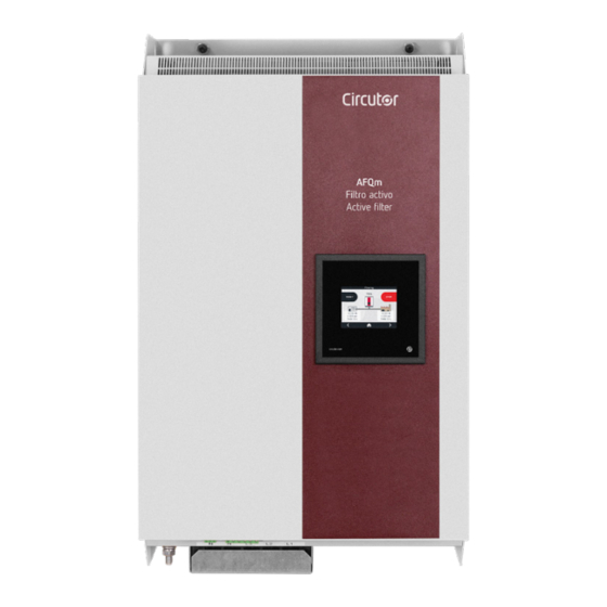
- Page 1 Filtro Activo Paralelo Multifunción Active Parallel Multi-Function Filter AFQm MANUAL DE INSTRUCCIONES INSTRUCTION MANUAL (M217B01-20-21A)
- Page 2 AFQm...
-
Page 3: Contenido - Contents
AFQm CONTENIDO - CONTENTS MANUAL DE INSTRUCCIONES ............................4 INSTRUCTION MANUAL ..............................117... -
Page 4: Precauciones De Seguridad
En el presente manual, si las instrucciones precedidas por este símbolo no se respetan o realizan correctamente, pueden ocasionar daños personales o dañar el equipo y /o las instalaciones. CIRCUTOR, SA se reserva el derecho de modificar las características o el manual del producto, sin previo aviso. LIMITACIÓN DE RESPONSABILIDAD CIRCUTOR, SA se reserva el derecho de realizar modificaciones, sin previo aviso, del equipo o a las especificaciones del equipo, expuestas en el presente manual de instrucciones. -
Page 5: Table Of Contents
3.6.1.- AFQm TIPO MURAL: AFQm-xxx-030M, AFQm-xxx-060M y AFQm-xxx-100M ..........23 3.6.2.- AFQm TIPO RACK: AFQm-xxx-100R ......................25 3.6.3.- AFQm TIPO ARMARIO: AFQm-xxx-100C, AFQm-xxx-200C, AFQm-xxx-300C y AFQm-xxx-400C ....26 3.6.4.- AFQm TIPO ARMARIO: AFQm-xxx-070C, AFQm-xxx-140C, AFQm-xxx-210C y AFQm-xxx-280C ....28 3.7.- ESQUEMAS DE CONEXIONADO ..........................30 3.7.1.- CONEXIÓN A 4 HILOS Y MEDIDA DE CORRIENTE EN EL LADO DE RED. - Page 6 10.6.- CAMBIO DE VENTILADORES DE REFRIGERACIÓN: AFQm DE 100A MURAL ............100 10.7.- CAMBIO DE VENTILADORES DE REFRIGERACIÓN: AFQm TIPO ARMARIO ............101 10.8.- MANTENIMIENTO DE LOS PROTECTORES DE SOBRETENSIÓN: AFQm TIPO ARMARIO DE 70A, 140A, 210A Y 280A ..................................... 102 11.- CARACTERÍSTICAS TÉCNICAS ............................103...
-
Page 7: Histórico De Revisiones
AFQm HISTÓRICO DE REVISIONES Tabla 1: Histórico de revisiones. Fecha Revisión Descripción 03/19 M217B01-20-19A Versión Inicial Modificaciones en los apartados: 04/19 M217B01-20-19B Modificaciones en los apartados: 09/19 M217B01-20-19C 3.5. - 4.6.2. - 6.3. - 6.16. - 7.6. - 7.7. - 7.8. - 7.13. - 11. -
Page 8: Comprobaciones A La Recepción
Compruebe que está equipado con: - Un manual de instrucciones, - Cable de comunicaciones para la conexión de equipos en paralelo (Modelos AFQm tipo Mural y Rack). e) Realizar una inspección visual externa e interna del equipo antes de conectarlo. - Page 9 Los equipos AFQm tipo armario, incorporan 4 anillas (28 mm de diámetro) en el techo para su tras- porte mediante grúa. El techo se encuentra invertido, pero las anillas están montadas, para permitir su transporte sin necesidad de ninguna operación previa.
-
Page 10: Almacenaje
AFQm 1.3.- ALMACENAJE Para el almacenaje del equipo deben seguirse las siguientes recomendaciones: Evitar la colocación sobre superficies irregulares. No ubicar en zonas exteriores, húmedas o expuestas a proyección de agua. Evitar los focos de calor (máxima temperatura ambiente: 50 ºC) Evitar ambientes salinos y corrosivos. -
Page 11: Descripción Del Producto
AFQm 2.- DESCRIPCIÓN DEL PRODUCTO Los filtros activos multifunción AFQm, permiten : Reducir de las corrientes armónicas hasta el orden de 50. Corregir el consumo desequilibrado de corrientes en cada fase de la instalación eléctrica. Compensar la potencia reactiva. Tanto de corrientes atrasadas (inductiva) como adelantadas (capacitiva). - Page 12 AFQm - Envolvente tipo Mural. Tabla 4:Relación de modelos AFQm de 60A. 3 Hilos 4 Hilos Tensión de red Modelo ( L1, L2, L3) ( L1, L2, L3, N) (Un) AFQm-3WF-060M-480 208 ... 480 V AFQm-4WF-060M-400 208 ... 400 V ...
- Page 13 - Paralelización hasta en 100 unidades. - Display LCD táctil, para visualizar los parámetros - Comunicaciones RS-485 y Ethernet. - Filtros EMI. - Envolvente tipo Rack, Armario o Mural. Tabla 6:Relación de modelos AFQm de 100A. Tipo 3 Hilos 4 Hilos Tensión de red...
- Page 14 - Display LCD táctil, para visualizar los parámetros - Comunicaciones RS-485 y Ethernet. - Envolvente tipo Armario. - Filtros EMI. Tabla 7:Relación de modelos AFQm de 140A, 200A, 210A, 280A, 300A y 400A. 3 Hilos 4 Hilos Tensión de red...
-
Page 15: Instalación Del Equipo
AFQm 3.- INSTALACIÓN DEL EQUIPO 3.1.- RECOMENDACIONES PREVIAS La instalación del equipo y las operaciones de mantenimiento debe realizarse solo por personas autorizadas y cualificadas. Para la utilización segura del equipo es fundamental que las personas que lo manipulen sigan las medidas de seguridad estipuladas en las normativas del país donde se está... -
Page 16: Emplazamiento
Para mantener las prestaciones del equipo, se recomienda que se asegure la libre circulación de aire por el frontal del AFQm tipo Rack, y que la parte posterior esté libre de obstáculos, como mínimo, 300 Manual de Instrucciones... - Page 17 300 mm 3.2.1.3.- AFQm tipo Armario Los AFQm tipo Armario utilizan una refrigeración basada en ventilación forzada, con una entrada de aire por el frontal, y una salida de aire por la parte superior del equipo. No se debe obstruir la rejilla de la parte superior, debiendo dejar espacio suficiente hasta el techo para permitir la evacuación de calor.
-
Page 18: Almacenamiento Durante Un Largo Periodo
Alimentar el equipo y dejarlo en modo STOP 3.4.- INSTALACIÓN 3.4.1.- AFQm TIPO MURAL El AFQm tipo Mural dispone de unos agujeros en la parte inferior y superior del equipo, para Figura 4, facilitar su transporte e instalación. -
Page 19: Afqm Tipo Rack
2.- Abrir o desmontar la puerta frontal del armario. 3.- Colocar el AFQm sobre los rieles o estantes del armario. Comprobar que sean adecuados para el peso del equipo, en caso necesario utilizar refuerzos transversales. No utilizar las asas frontales del equipo para transportarlo. -
Page 20: Afqm Tipo Armario
4.- Sujetar el equipo en los puntos previstos para ello. Utilizar 4 tornillos de fijación de M6. 3.4.3.- AFQm TIPO ARMARIO Los modelos AFQm tipo Armario, son armarios autoportantes con 4 puntos de apoyo en el suelo. Es obligatorio que la superficie de montaje sea sólida, soporte el peso del equipo, y se encuentre nivelada. -
Page 21: Conexión
Comprobar que el AFQm está correctamente conectado a tierra para evitar el riesgo de descarga eléctrica. Para la medida de corriente se recomienda usar transformadores de clase 0.2S de la serie TC o TCH. - Page 22 AFQm La conexión correcta de los transformadores de corriente es fundamental para el buen funcionamiento de los filtros AFQm. Si se permutan en el secundario las fases L1, L2 y L3 el filtro no funcionará correctamente. Los AFQm disponen de protección integrada frente a sobrecorriente mediante fusibles.
-
Page 23: Bornes Del Equipo
3.6.1.- AFQm TIPO MURAL: AFQm-xxx-030M, AFQm-xxx-060M y AFQm-xxx-100M Los bornes de conexión de los modelos AFQm tipo Mural, se encuentran en la cara inferior del equipo. El equipo dispone de una tapa cubre bornes en los bornes de conexión a red. - Page 24 10: S1, Entrada de corriente L2 9 10 11 12 13 L1 L2 L3 LINK RS485 ETHERNET R BUS 17 18 Figura 10: Bornes AFQm-xxx-030M y AFQm-xxx-060M. 9 10 11 12 13 L1 L2 L3 RS485 LINK ETHERNET R BUS A B S Figura 11: Bornes AFQm-xxx-100M.
-
Page 25: Afqm Tipo Rack: Afqm-Xxx-100R
AFQm 3.6.2.- AFQm TIPO RACK: AFQm-xxx-100R Los bornes de conexión del modelo AFQm-xxx-100R, se encuentran en la parte frontal y posterior del equipo. Tabla 13:Relación de bornes. Bornes del equipo 1: ETHERNET, Conector Ethernet 11: S2, Entrada de corriente L2 2: R , Selector del terminador para la conexión en paralelo 12: S1, Entrada de corriente L3... -
Page 26: Afqm Tipo Armario: Afqm-Xxx-100C, Afqm-Xxx-200C, Afqm-Xxx-300C Y Afqm-Xxx-400C
3.6.3.- AFQm TIPO ARMARIO: AFQm-xxx-100C, AFQm-xxx-200C, AFQm-xxx-300C y AFQm-xxx- 400C CIRCUTOR dispone de dos tipos de armarios, armarios con las conexiones en la parte superior y arma- rios con las conexiones en la parte inferior. Los armarios con las conexiones en la parte inferior, dispone de unas ventanas inferiores que se desli- zan para permitir la entrada del cableado de conexión,... - Page 27 Figura 17, Figura 18 y Figura 19 Figura 17: Bornes AFQm tipo Armario de 100, 200, 300 y 400A (Conexiones en la parte inferior). Figura 18: Bornes AFQm tipo Armario de 100, 200, 300 y 400A (Conexiones en la parte superior).
-
Page 28: Afqm Tipo Armario: Afqm-Xxx-070C, Afqm-Xxx-140C, Afqm-Xxx-210C Y Afqm-Xxx-280C
AFQm Figura 19: Borne de tierra en AFQm tipo Armario. Tabla 14: Relación de bornes. Bornes del equipo 1: S1, Entrada de corriente L1 6: S2, Entrada de corriente L3 2: S2, Entrada de corriente L1 7: L1, Conexión a la Red L1 3: S1, Entrada de corriente L2 8: L2, Conexión a la Red L2... - Page 29 ARMARIO DE 70A, 140A, 210A Y 280A” Una vez abierta la tapa frontal, se accede a los bornes del equipo, Figura 21 Figura 21: Bornes AFQm tipo Armario 70, 140, 210 y 280A. En la se visualiza la posición del borne de tierra.
-
Page 30: Esquemas De Conexionado
AFQm 3.7.- ESQUEMAS DE CONEXIONADO 3.7.1.- CONEXIÓN A 4 HILOS Y MEDIDA DE CORRIENTE EN EL LADO DE RED. P2 P1 L1 L2 L3 S1 S2 S1 S2 S1 S2 CARGA / LOAD RED/ MAINS P2 S1 Figura 22: Medida trifásica con conexión a 4 hilos y medida de corriente en el lado de Red. -
Page 31: Conexión A 4 Hilos Y Medida De Corriente En El Lado De Carga
AFQm 3.7.2.- CONEXIÓN A 4 HILOS Y MEDIDA DE CORRIENTE EN EL LADO DE CARGA. P2 P1 S1 S2 S1 S2 S1 S2 CARGA / LOAD RED/ MAINS P2 S1 Figura 23: Medida trifásica con conexión a 4 hilos y medida de corriente en el lado de Carga. -
Page 32: Conexión A 3 Hilos Y Medida De Corriente En El Lado De Red
AFQm 3.7.3.- CONEXIÓN A 3 HILOS Y MEDIDA DE CORRIENTE EN EL LADO DE RED. P2 P1 L1 L2 L3 S1 S2 S1 S2 S1 S2 RED/ MAINS CARGA / LOAD P2 S1 Figura 24: Medida trifásica con conexión a 3 hilos y medida de corriente en el lado de Red. -
Page 33: Conexión A 3 Hilos Y Medida De Corriente En El Lado De Carga
AFQm 3.7.4.- CONEXIÓN A 3 HILOS Y MEDIDA DE CORRIENTE EN EL LADO DE CARGA. P2 P1 S1 S2 S1 S2 S1 S2 CARGA / LOAD RED/ MAINS P2 S1 Figura 25: Medida trifásica con conexión a 3 hilos y medida de corriente en el lado de Carga. -
Page 34: Conexión A 3 Hilos Y 2 Transformadores De Corriente En El Lado De Red
AFQm 3.7.5.- CONEXIÓN A 3 HILOS Y 2 TRANSFORMADORES DE CORRIENTE EN EL LADO DE RED. P2 P1 L1 L2 L3 S1 S2 S1 S2 S1 S2 RED/ MAINS CARGA / LOAD Figura 26: Medida trifásica con conexión a 3 hilos y 2 transformadores de corriente en el lado de Red. -
Page 35: Conexión A 3 Hilos Y 2 Transformadores De Corriente En El Lado De Carga
AFQm 3.7.6.- CONEXIÓN A 3 HILOS Y 2 TRANSFORMADORES DE CORRIENTE EN EL LADO DE CARGA. P2 P1 S1 S2 S1 S2 S1 S2 CARGA / LOAD RED/ MAINS Figura 27: Medida trifásica con conexión a 3 hilos y 2 transformadores corriente en el lado de Carga. -
Page 36: Conexionado De 2 A 100 Filtros Activos En Paralelo
AFQm 3.8.- CONEXIONADO DE 2 A 100 FILTROS ACTIVOS EN PARALELO Los equipos AFQm permiten su colocación en paralelo para incrementar la potencia de filtrado dispo- nible. Es posible colocar hasta 100 equipos en paralelo, que pueden ser del modelo de 30A, 60A, 70A o 100A. -
Page 37: Conexión De Equipos Individuales
AFQm 3.8.1.- CONEXIÓN DE EQUIPOS INDIVIDUALES Los pasos a seguir para conectar múltiples equipos individuales en paralelo son: 1.- Seleccionar el equipo que funcionará como “maestro”. 2.- Realizar la conexión del equipo “maestro”. Los transformadores de corriente se conectan solo al equipo “maestro”. -
Page 38: Conexión De Armarios
Esclavo AFQm-xxx-200C (*) Conexiones ya incluidas en los armarios Figura 31: Conexión de 3 equipos en paralelo, mediante el cable de comunicaciones (Maestro AFQm 200A). 5.- Realizar la configuración de la instalación en el equipo “maestro” (ver “7.- CONFIGURACIÓN” 6.- Realizar la configuración de los equipos esclavos (ver “7.- CONFIGURACIÓN”... -
Page 39: Funcionamiento
AFQm 4.- FUNCIONAMIENTO 4.1.- ARMÓNICOS Las cargas no lineales tales como: rectificadores, inversores, variadores de velocidad, hornos, etc, ab- sorben de la red corrientes periódicas no senoidales. Estas corrientes están formadas por una componente fundamental de frecuencia 50 ó 60 Hz, más una serie de corrientes superpuestas de frecuencias múltiplos de la fundamental, que denominamos... -
Page 40: Armónicos Más Habituales
�������� �������� ∗ 100 �������� �������� �������� �������� AFQm �������� ∗ 100 �������� �������� �������� ���� ���� ∗ 100 ���� Tasa de distorsión individual (U % o I %): Relación en % entre el valor eficaz de la tensión o ����... -
Page 41: Compensación De Armónicos
AFQm Tabla 18: Armónicos más habituales. Tipo de carga Forma de onda Espectro armónico THD(I) Convertidores 6 pulsos Variadores de velocidad Rectificadores trifásicos Convertidores para electrólisis y baños Lámparas de descarga Convertidores monofásicos Líneas de iluminación Líneas de ordenadores Equipos de imagen y sonido 4.1.3.- COMPENSACIÓN DE ARMÓNICOS... -
Page 42: Principio De Funcionamiento
El filtro activo adquirido debe estar dimensionado para las corrientes de armónicos que debe filtrar. La corriente nominal del AFQm debe ser como mínimo un 20% superior al nivel máximo de armónicos a filtrar. Este factor puede ser mayor según las características de la instalación. - Page 43 FILTRO caRga Donde: ����� + ���� + ���� + ⋯ (AFQm): corriente nominal del filtro activo. ������������ ( ���� ) % = ���� FILTRO : factor de seguridad > 1.2 : corriente máxima de la carga. CARGA THD(I): distorsión armónica de la corriente de carga.
-
Page 44: Detección De Resonancia
En algún caso, puede existir alguna carga que ofrezca una menor impedancia que la red eléctrica, en cuyo caso se producirá un fenómeno de resonancia con esa carga. El AFQm dispone de un sistema de detección de resonancia con cargas, que automáticamente desactiva el armónico que provoca esa resonancia. -
Page 45: Protección Térmica
AFQm 4.6.- PROTECCIÓN TÉRMICA El equipo dispone de varios niveles de protección térmica: Regulación de la ventilación, la velocidad de los ventiladores se ajusta según la necesidad en cada momento, minimizando así el ruido del equipo. Limitación estática de la temperatura, el equipo reduce su potencia si la temperatura interna supera unos límites establecidos. -
Page 46: Área Superior
AFQm Área superior Área central Lorem ipsum Área inferior Figura 38: El display se divide en tres áreas. 4.7.1.- ÁREA SUPERIOR En el área superior se visualiza: Una pequeña descripción con el estado del equipo. El símbolo , si es necesario realizar el mantenimiento del equipo, ver apartado “10.- MANTENI-... -
Page 47: Área Inferior
AFQm Tabla 19: Teclas del área central. Tecla Función Reinicia el equipo después de una alarma. Arranque del filtro activo. Paro del filtro activo. 4.7.3.- ÁREA INFERIOR Figura 40: Área inferior. En el área inferior aparecen las teclas de navegación y configuración del equipo. -
Page 48: Puesta En Marcha
AFQm 5.- PUESTA EN MARCHA Una vez alimentado el equipo en el display aparece una de las pantallas de la Figura 41 Pantalla equipo “único” o “maestro” Pantalla equipo “esclavo” Figura 41: Pantalla inicial. Antes de arrancar el filtro activo es necesario seguir los siguientes pasos: 1.- Utilizar la tecla... -
Page 49: Visualización
En la parte superior de la pantalla se visualiza un mensaje con el estado actual del equipo ( Tabla 21 Tabla 21: Mensajes de estado Mensajes de Estado Arrancando Descripción AFQm arrancando. Iniciando Descripción Equipo iniciando los sistemas. Esperando comms Descripción Iniciando sistemas de comunicación internos... -
Page 50: Equipo Esclavo
Configuración Descripción Realizando la configuración del equipo. Marcha Descripción Equipo en funcionamiento. Sincronizando Descripción El AFQm está sincronizando con la Red. Cargando bus DC Descripción Proceso de carga del bus interno previo al arranque. Parado Descripción Equipo parado. Alarma Se ha generado una alarma. -
Page 51: Thd
AFQm 6.2.- THD Nota: Esta pantalla no es visible en los equipos “esclavos”. Al pulsar la tecla desde la pantalla principal se accede a la pantalla de visualización del THD. Figura 44: Visualización del THD. Donde se visualiza: El THD de tensión en cada una de las fases, L1, L2 y L3. -
Page 52: Corriente Armónica
AFQm 6.4.- CORRIENTE ARMÓNICA Nota: Esta pantalla no es visible en los equipos “esclavos”. En la se muestra la corriente armónica en valor absoluto de cada una de las fases en la Red Figura 46 y en la Carga. Figura 46: Corriente armónica Utilizar las teclas para desplazarse por las diferentes pantallas de visualización. -
Page 53: Potencia Y Cos ɸ De Red
AFQm 6.6.- POTENCIA Y COS ɸ DE RED Nota: Esta pantalla no es visible en los equipos “esclavos”. En la se muestra la potencia y el cos ɸ de la red. Figura 48 Figura 48: Visualización de la potencia y cos ɸ de la red. -
Page 54: Armónicos De Tensión
AFQm La Potencia Activa (P), Reactiva (Q) y Aparente (S). El cos ɸ. Nota: En la potencia reactiva el signo - indica que la potencia es capacitiva y el signo + que la potencia es inductiva. Utilizar las teclas para desplazarse por las diferentes pantallas de visualización. -
Page 55: Armónicos De Corriente (Carga)
AFQm 6.10.- ARMÓNICOS DE CORRIENTE (CARGA) Nota: Esta pantalla no es visible en los equipos “esclavos”. En esta pantalla, , se visualizan los armónicos impares de la corriente de carga, del 3 al 25, de Figura 52 cada una de las fases. -
Page 56: Forma De Onda De La Corriente De Red
AFQm 6.12.- FORMA DE ONDA DE LA CORRIENTE DE RED Nota: Esta pantalla no es visible en los equipos “esclavos”. En esta pantalla, , se visualiza la forma de onda de la corriente de Red de cada una de las Figura 54 fases. -
Page 57: Fasores De Red
AFQm 6.14.- FASORES DE RED Nota: Esta pantalla no es visible en los equipos “esclavos”. En esta pantalla, , se visualizan los fasores de red. Figura 56 Figura 56: Fasores de Red. Utilizar las teclas para desplazarse por las diferentes pantallas de visualización. -
Page 58: Alarmas
AFQm 6.16.- ALARMAS Nota: Esta pantalla no es visible en los equipos “esclavos”. En esta pantalla, , se visualizan las alarmas que se han producido. Figura 58 Figura 58: Alarmas. En la pantalla se visualiza una pequeña descripción de la alarma y la fecha y hora en la que se ha producido. - Page 59 Tabla 22: Mensajes de alarma. Mensajes de alarma Sobrecorriente L1/L2/L3 Descripción La corriente del AFQm es demasiado alta. Acción Esta alarma puede ir asociada a transitorios y ruido en la tensión de alimentación. Comprobar la cali- correctora dad de tensión de alimentación. Si persiste, contactar con SAT Sobretensión red L1/L2/L3...
-
Page 60: Advertencias
AFQm 6.17.- ADVERTENCIAS Nota: Esta pantalla no es visible en los equipos “esclavos”. Cuando el equipo genera una advertencia, este sigue funcionando normalmente, pero en la pantalla principal se muestra en símbolo Al pulsar la tecla , si hay advertencias activas, aparece la pantalla de la... - Page 61 AFQm Tabla 23 (Continuación): Mensajes de advertencia. Mensajes de advertencias Polaridad carga Descripción Detección de error en polaridad de la carga. Acción Comprobar conexionado de transformadores. Consular apartado de “7.9.- CONFIGURACIÓN DE LOS correctora TRANSFORMADORES” Armónico X deshabilitado Descripción Se ha deshabilitado el armónico X por resonancia.
-
Page 62: Temperatura
AFQm Tabla 23 (Continuación): Mensajes de advertencia. Mensajes de advertencias Potencia negativa La potencia medida es negativa (potencia generada), lo que puede indicar que los transformadores Descripción se han conectado de forma invertida. Acción Confirmar que el conexionado en correcto. -
Page 63: Comunicaciones Ethernet
AFQm 6.19.- COMUNICACIONES ETHERNET En esta pantalla, , se visualizan la dirección IP del equipo y la mascara de red. Figura 63 Figura 63: Comunicaciones. Utilizar las teclas para desplazarse por las diferentes pantallas de visualización. 6.20.- INFORMACIÓN DEL EQUIPO En esta pantalla, , se visualiza el número de serie y las versiones HMI y DSP del equipo. -
Page 64: Estado De Los Equipos Esclavos
AFQm Figura 65: Calibrar sensor táctil. Nota: Si ha accedido a la pantalla de calibración por accidente, espere a que se complete la línea que rodea el círculo central y regresará a la pantalla de información del equipo de forma automática... - Page 65 AFQm Figura 67: Pantalla de estado de los equipos esclavos (2). Nota: Si existen problemas de comunicaciones, aparece el texto “Error comunicaciones” al seleccionar el equipo afectado. Manual de Instrucciones...
-
Page 66: Configuración
AFQm 7.- CONFIGURACIÓN En la, , se muestra la pantalla principal de configuración. Figura 68 Figura 68: Pantalla principal de configuración. Al pulsar la tecla se accede al menú de configuración en modo visualización, es decir, se visualizan todos los parámetros del equipo pero no se pueden modificar. -
Page 67: Idioma
AFQm 7.1.- IDIOMA En esta pantalla, , se selecciona el idioma del display. Figura 70 Figura 70: Pantalla de configuración: Idioma. ● Idioma, idioma del display. Pulsar la tecla para acceder al siguiente paso de configuración Pulsar la tecla para acceder a la pantalla principal del equipo, sin guardar los valores de configu- ración. -
Page 68: Equipos Instalados
En esta pantalla se selecciona el tipo de equipo, las posibles opciones son: Único: seleccionar esta opción si el AFQm no tiene filtros conectados en paralelo. Maestro: seleccionar esta opción si el filtro va a trabajar como “maestro” de un grupo de equipos en paralelo. -
Page 69: Modo De Trabajo
AFQm 7.4.- MODO DE TRABAJO Nota: Esta pantalla no es visible en los equipos “esclavos”. En esta pantalla, , se configuran los siguientes parámetros del modo de trabajo de equipo: Figura 73 Figura 73: Pantalla de configuración: Modo de trabajo. - Page 70 AFQm La opción de equilibrado de fases en el AFQm-3WF-xxxx funciona en desequilibrios producidos por cargas conectadas entre fases en redes trifásicas sin neutro. El AFQm- 3WF-xxxx no compensa desequilibrios producidos por cargas monofásicas conectadas entre fase y neutro. Para corregir este tipo de desequilibrios utilizar un AFQm-4WF- xxxx.
-
Page 71: Selección De Armónicos
En este parámetro se configura la corriente mínima de la carga para arrancar el filtro. La corriente mí- nima se utiliza para incrementar la eficiencia del sistema, manteniendo en standby el filtro cuando se requiera. El AFQm se parará cuando la corriente de carga sea inferior al valor introducido y arrancará Manual de Instrucciones... -
Page 72: Cos Φ
AFQm cuando sea mayor. Rango de valores: Valor mínimo: 0 A Valor máximo: 5000 A ● Limite corriente Este parámetro permite limitar la potencia máxima del filtro activo. El valor se configura en porcentaje respeto a la potencia nominal del equipo. -
Page 73: Ieee519
AFQm configurada. Este modo permite minimizar la potencia del equipo usada para compensar la reactiva, y por lo tanto, reducir su consumo energético. Rango de valores: 0.7 ... -0.7 Pulsar la tecla para acceder al siguiente paso de configuración Pulsar la tecla para acceder a la pantalla principal del equipo, sin guardar los valores de configu- ración. - Page 74 AFQm sitos de los límites establecidos, en lugar de buscar la cancelación total de armónicos. ● Generator La norma IEEE519-2014 establece unos límites más restrictivos si la instalación es generadora. Por ello es necesario marcar la casilla correspondiente en caso de que pueda exportar energía.
-
Page 75: Configuración De Los Transformadores
CARGA: Si se han instalado los transformadores en la zona de la carga, aguas abajo del AFQm. RED: Si se han instalado los transformadores en la zona de red, aguas arriba del AFQm. ● Relación En este parámetro se configura el ratio de los transformadores, es decir la relación entre el primario y el secundario del transformador. -
Page 76: Alarmas
AFQm Valor mínimo: 5 A Valor máximo: 5000 A ● Invertir En este parámetro se selecciona la fase sobre la que el filtro va a invertir el sentido de la corriente de los transformadores de medida de carga, de esta manera se pueden corregir errores de instalación. -
Page 77: Comunicaciones Ethernet
7.12.- COMUNICACIONES RS-485 La configuración de las comunicaciones RS-485 en los AFQm, está fijada a una Velocidad de trans- misión de 9600 bps, 8 bits de Datos, 1 bit de Stop y Sin Paridad. Únicamente se puede configurar la dirección Modbus del equipo,... -
Page 78: Fecha / Hora
AFQm ● Dispositivo Modbus, dirección modbus del equipo. Pulsar la tecla para acceder al siguiente paso de configuración. Pulsar la tecla para acceder a la pantalla principal del equipo, sin guardar los valores de configu- ración. 7.13.- FECHA / HORA En esta pantalla, , se configuran los parámetros horarios:... -
Page 79: Guardar Datos
AFQm ● Setup Password. Esté parámetro permite modificar el password de acceso a la configuración del equipo. ● Stop Password. Es posible introducir un password al acceso de la tecla , si se activa, al pulsar la tecla el equi- po solicita el password y no para el equipo si el password no es correcto. -
Page 80: Comunicaciones Rs-485
8.1.- CONEXIONADO La composición del cable RS-485 se deberá llevar a cabo mediante cable de par trenzado con malla de apantallamiento (mínimo 3 hilos), con una distancia máxima entre el AFQm y la unidad master de 1200 metros de longitud. -
Page 81: Protocolo
AFQm 8.2.- PROTOCOLO Dentro del protocolo Modbus el AFQm utiliza el modo RTU (Remote Terminal Unit). Las funciones Modbus implementadas en el equipo son: Función 03 y 04: Lectura de n Words (2 bytes). 8.2.1.- EJEMPLO DE PREGUNTA MODBUS Pregunta: Valor de la corriente de Carga de la L1 Registro Dirección... - Page 82 AFQm Tabla 26: Mapa de memoria Modbus: Medidas en la Carga (Tabla 2). Parámetro Corriente L1 Corriente L2 Corriente L3 Unidades Armónico fundamental 3º Armónico 5º Armónico 7º Armónico 9º Armónico 11º Armónico 13º Armónico 15º Armónico 17º Armónico 19º Armónico 21º...
- Page 83 Tabla 32: Mapa de memoria Modbus: Medidas en la Red (Tabla 4). Parámetro Unidades Corriente fundamental Corriente armonicos 8.2.2.3.- Otros parámetros del filtro AFQm Tabla 33: Mapa de memoria Modbus: Parámetros del filtro (Tabla 1). Parámetro Dirección Unidades Temperatura IGBT 1 ºC con 1 decimal...
- Page 84 % con 1 decimal Tabla 35: Mapa de memoria Modbus: Parámetros del filtro (Tabla 3). Parámetro Dirección Descripción Nº de serie del AFQm 2710 - 2711 Nº de serie Hi [10] + Low [11] Versión del software del DSP Versión del software HMI En un sistema de equipos en paralelo, el valor del parámetro es el del equipo conectado con RS-485.
- Page 85 En un sistema de equipos en paralelo, el valor del parámetro es el del equipo conectado con RS-485. Tabla 39: Mapa de memoria Modbus: Mensajes del filtro (Tabla 4). Parámetro Dirección Estado del AFQm Estado ( Valor en decimal) Descripción Arranque 10, 20, 30 Calibración...
- Page 86 AFQm Tabla 40: Mapa de memoria Modbus: Mensajes del filtro (Tabla 5). Parámetro Dirección Estado de los armónicos Descripción Estado 0x0001 Armónico 3 0x0002 Armónico 5 0x0004 Armónico 7 0x0008 Armónico 9 0x0010 Armónico 11 1: Armónico filtrándose 0x0020 Armónico 13 0: Armónico deshabilitado...
-
Page 87: Comunicaciones Ethernet
9.1.- CONEXIÓN El AFQm dispone de un puerto Ethernet. Este tipo de comunicación crea una red interna con comuni- caciones vía IP. Si el equipo que se conecta a éste puerto es un ordenador, el cable de red debe ser un cable Ethernet cruzado, según se muestra en la... - Page 88 AFQm El idioma de la página web se puede modificar a partir de los botones que aparecen en la parte supe- rior derecha de la página. Para poder modificar los parámetros de Configuración es necesario introducir el Usuario y Contraseña en el apartado Administrador.
-
Page 89: Mantenimiento
Seguir las instrucciones de seguridad descritas en el apartado “ PRECAUCIONES DE SE- ” antes de efectuar cualquier operación de mantenimiento en los filtros AFQm. GURIDAD Omitir estas instrucciones puede producir lesiones o incluso la muerte. - Page 90 AFQm Los puntos a seguir son: 1.- Poner el AFQm en modo STOP y abrir el interruptor general (posición OFF). 2.- Esperar 1 minuto para que se descarguen los condensadores. 3.- Limpiar las rejillas de ventilación, aspirando el polvo. 4.- Verificar el estado y el apriete de las conexiones eléctricas, así como de la fijación mecánica a la pared.
-
Page 91: Ventiladores De Refrigeración
Reducción de la capacidad de filtrado. Es necesario cambiar el conjunto de ventiladores, si estos han sobrepasado su vida útil, o si muestran un deterioro. Para ello, CIRCUTOR ofrece un recambio, que consiste en un conjunto de ventiladores, para poder proceder a su repuesto. - Page 92 AFQm Para proceder a cambiar el conjunto de ventiladores: Poner el AFQm en modo STOP y quitar la alimentación del equipo. Desconectar todos los cables de conexión y cortocircuitar los transformadores de corriente, si es necesario. Esperar 1 minuto para que se descarguen los condensadores, antes de abrir el equipo.
- Page 93 15 Conectar la pantalla. 16 Apretar tornillos de tapa frontal. 1.5 Nm 17 Conectar, alimentar y poner en marcha el AFQm. 18 Comprobar el correcto funcionamiento de los ventiladores. Figura 92: Pantalla de mantenimiento. Para ello acceder a la pantalla de mantenimiento, a través de la pantalla de configuración, pulsando...
-
Page 94: Cambio De Ventiladores De Refrigeración: Afqm De 60A
Figura 93: Situación de los ventiladores de refrigeración. Para proceder a cambiar el conjunto de ventiladores: 1 Poner el AFQm en modo STOP y quitar la alimentación del equipo. Desconectar todos los cables de conexión y cortocircuitar los transformadores de corriente, si es necesario. - Page 95 AFQm Tapa frontal Pasamuros Tapa inferior Figura 94: Pasos para realizar el cambio de ventiladores (parte 1). Figura 95: Pasos para realizar el cambio de ventiladores (parte 2). 3 Quitar los 8 tornillos de la tapa frontal 4 Desconectar la pantalla.
- Page 96 AFQm 5 Quitar los aislantes. 6 Quitar los tornillos de los fusibles y pletina de la conexión de neutro del lado de placa. 7 Aflojar los tornillos de los fusibles del lado de la bornera. 8 Quitar los fusibles. 9 Quitar los 5 tornillos de la bornera. Quitar la pletina de cada una de las fases.
-
Page 97: Cambio De Ventiladores De Refrigeración: Afqm De 100A Rack
Destornillador para tornillos de cabeza Hexagonal 10 mm Para proceder a cambiar el conjunto de ventiladores: 1 Poner el AFQm en modo STOP y quitar la alimentación del equipo. Desconectar todos los cables de conexión y cortocircuitar los transformadores de corriente, si es necesario. - Page 98 8 Quitar los tornillos de las pletinas ( ), y los tornillos que hay el extremo de la inductancia (tipo 10mm). Figura 98: AFQm-xxx-100R cambio ventiladores (Paso 5, 6, 8). 9 Quitar los 3 tornillos de los ventiladores. Manual de Instrucciones...
- Page 99 AFQm Figura 99: AFQm-xxx-100R cambio ventiladores (Paso 9). 10 Sacar el conjunto de los ventiladores tirando hacia arriba, y reemplazar por los nuevos ventiladores. Figura 100: AFQm-xxx-100R cambio ventiladores (Paso 10). 11 Apretar los tornillos del conjunto de ventiladores. 5.5 Nm 12 Montar las pletinas.
-
Page 100: Cambio De Ventiladores De Refrigeración: Afqm De 100A Mural
Destornillador para tornillos de cabeza Hexagonal 10 mm Para proceder a cambiar el conjunto de ventiladores: 1 Poner el AFQm en modo STOP y quitar la alimentación del equipo. Desconectar todos los cables de conexión y cortocircuitar los transformadores de corriente, si es necesario. -
Page 101: Cambio De Ventiladores De Refrigeración: Afqm Tipo Armario
Destornillador para tornillos de cabeza Hexagonal 10 mm Para proceder a cambiar el conjunto de ventiladores: 1 Poner el AFQm en modo STOP y quitar la alimentación del equipo. Desconectar todos los cables de conexión y cortocircuitar los transformadores de corriente, si es necesario. -
Page 102: Mantenimiento De Los Protectores De Sobretensión: Afqm Tipo Armario De 70A, 140A, 210A Y 280A
Nota: Al realizar la comprobación de ventiladores en el equipo “maestro”, se activarán de forma auto- mática los ventiladores de los equipos esclavo. 10.8.- MANTENIMIENTO DE LOS PROTECTORES DE SOBRETENSIÓN: AFQm TIPO ARMARIO DE 70A, 140A, 210A Y 280A El equipo dispone de protectores de sobretensión extraibles, accesibles desde el frontal. Estos incor- poran un indicador de color verde que indica el correcto funcionamiento del protector. -
Page 103: Características Técnicas
AFQm 11.- CARACTERÍSTICAS TÉCNICAS Tensión de red AFQm-3WF-xxxx-480 AFQm-4WF-xxxx-400 208 ... 480 V~ ± 10% 208 ... 400 V~ ± 10% Tensión asignada Un AFQm-3WF-xxxx-690 AFQm-4WF-xxxx-550 230 ... 690 V~ ± 10% 230 ... 550 V~ ± 10% Frecuencia Fn 50 / 60 Hz ±... - Page 104 AFQm (Continuación) AFQm-xxx-300C AFQm-xxx-400C Corriente de cortocircuito condicional Icc 40 kA 40 kA Simultaneidad RDF Consumo máximo 6210 W 8280 W Corriente máxima (fase) 300 A RMS 400 A RMS Corriente máxima (neutro) 900 A RMS 1200 A RMS Factor de cresta (corriente)
- Page 105 BS88A1, 25A, 500Vac gG 80kA I t 21kA AFQm-xxx-060M Cantidad 4 por fase Tipo BS88A1, 25A, 500Vac gG 80kA I t 21kA AFQm-xxx-100M, AFQm-xxx-100R Cantidad 2 por fase Tipo tipo BS88 100A, 500Vac, gG 80kA I t 76.5kA AFQm-xxx-070C Cantidad...
- Page 106 5000 m s.n.m. Grado de protección IP20 OVC III 300V Categoría de sobretensión AFQm-3WF-xxxC-690, AFQm-4WF-xxxC-550 OVC III 600V AFQm-xxx-070C, AFQm-xxx-100C, AFQm-xxx-140C, AFQm-xxx-200C, AFQm-xxx-210C, AFQm-xxx-280C, AFQm-xxx-300C, AFQm-xxx-400C Grado de contaminación Resistencia a impactos IK 10 Compatibilidad electromagnética Instalación en entornos tipo A Normas Compatibilidad Electromagnética (CEM).
- Page 107 AFQm Características mecánicas AFQm-xxx-030M Dimensiones (mm) Figura 104 Peso 21 kg Envolvente Acero galvanizado 1.5 mm Ruido 58 dBA Conexiones Tipo Terminal anilla M6 12 mm 2.2 ... 2.4 Nm Tierra Terminal anilla M6 16 mm 2.2 ... 2.4 Nm...
- Page 108 0.5 ... 0.6 Nm Plano 3 mm RS-485 Conector 3 polos max : 2.5 mm 0.5 ... 0.6 Nm Plano 3 mm Ethernet RJ-45 A 1 metro de la pared de montaje, Certificado ISO 11201:2010 V2 Figura 105: Dimensiones AFQm-xxx-060M Manual de Instrucciones...
- Page 109 Tipo Corriente Conector 6 polos max : 2.5 mm 0.5 ... 0.6 Nm Plano 3 mm RS-485 Conector 3 polos max : 2.5 mm 0.5 ... 0.6 Nm Plano 3 mm Ethernet RJ-45 Figura 106: Dimensiones AFQm-xxx-100M Manual de Instrucciones...
- Page 110 AFQm AFQm-xxx-100R Dimensiones (mm) Figura 107 Peso 55 kg Envolvente Acero galvanizado 1.5 mm Ruido < 60 dBA Conexiones Tipo Terminal anilla M8 23 mm 8 ... 10 Nm Tierra Terminal anilla M10 10 ... 14 Nm Hex 17 mm...
- Page 111 AFQm AFQm-xxx-070C, AFQm-xxx-100C, AFQm-xxx-140C, AFQm-xxx-200C, AFQm-xxx-210C, AFQm-xxx-280C, AFQm-xxx-300C, AFQm-xxx-400C Dimensiones (mm) Figura 108 AFQm-xxx-070C AFQm-xxx-100C AFQm-xxx-140C AFQm-xxx-200C 192 kg 190 kg 249 kg 245 kg Peso AFQm-xxx-210C AFQm-xxx-280C AFQm-xxx-300C AFQm-xxx-400C 306 kg 363 kg 300 kg 355 kg Armario autoportante de chapa de acero, para instalación en interior sin partes desmon- Envolvente tables.
- Page 112 AFQm Figura 108:Dimensiones AFQm tipo armario. Manual de Instrucciones...
-
Page 113: Servicio Técnico
13.- GARANTÍA CIRCUTOR garantiza sus productos contra todo defecto de fabricación por un período de dos años a partir de la entrega de los equipos. CIRCUTOR reparará o reemplazará, todo producto defectuoso de fabricación devuelto durante el pe- ríodo de garantía. -
Page 114: Certificado Ce
AFQm 14.- CERTIFICADO CE Manual de Instrucciones... - Page 115 AFQm Manual de Instrucciones...
- Page 116 AFQm Manual de Instrucciones...
-
Page 117: Safety Precautions
CIRCUTOR, SA reserves the right to make modifications to the device or the unit specifications set out in this instruction manual without prior notice. CIRCUTOR, SA on its web site, supplies its customers with the latest versions of the device specifica- tions and the most updated manuals. -
Page 118: Contents
3.6.- DEVICE TERMINALS............................. 136 3.6.1.- WALL-TYPE AFQm: AFQm-xxx-030M, AFQm-xxx-060M and AFQm-xxx-100M ........136 3.6.2.- RACK-TYPE AFQm: AFQm-xxx-100R ......................138 3.6.3.- CABINET-TYPE AFQm: AFQm-xxx-100C, AFQm-xxx-200C, AFQm-xxx-300C AND AFQm-xxx-400C ..139 3.6.4.- CABINET-TYPE AFQm: AFQm-xxx-070C, AFQm-xxx-140C, AFQm-xxx-210C AND AFQm-xxx-280C ..141 3.7.- CONNECTION DIAGRAMS ............................. 143 3.7.1.- 4-WIRE CONNECTION AND CURRENT MEASUREMENT ON THE MAINS SIDE. - Page 119 10.6.- CHANGE OF COOLING FANS: AFQm OF 100A WALL ..................213 10.7.- CHANGE OF COOLING FANS: CABINET TYPE AFQm ..................214 10.8.- MAINTENACE OF SURGE PROTECTIVE DECIVES: 70A, 140A, 210A AND 280A CABINET AFQm ......215 11.- TECHNICAL FEATURES ............................... 216 12.- TECHNICAL SERVICE ..............................226...
-
Page 120: Revision Log
AFQm REVISION LOG Table 1: Revision log. Date Revision Description 03/19 M217B01-20-19A Initial Version Change in the following sections: 04/19 M217B01-20-19B Change in the following sections: 09/19 M217B01-20-19C 3.5. - 4.6.2. - 6.3. - 6.16. - 7.6. - 7.7. - 7.8. - 7.13. - 11. -
Page 121: Verification Upon Reception
Check that it has been delivered with the following: - Instruction manual - Communication cable for connecting devices in parallel.(Models AFQm Wall and Rack type). e) Perform an external and internal visual inspection of the device prior to connecting it. - Page 122 The AFQm devices cabinet type, there are also 4 rings (diameter : 28 mm) in the top panel so that they can be transported by a crane. The top panel is inverted, but the rings are mounted, to enable it to be transported without any prior set-up required.
-
Page 123: Storage
AFQm 1.3.- STORAGE The device should be stored according to the following recommendations: Avoid placing them on uneven surfaces. Do not store them in outdoor areas, humid areas or areas exposed to splashing water. Avoid hot spots (maximum ambient temperature: 50ºC) Avoid salty and corrosive environments. -
Page 124: Product Description
AFQm 2.- PRODUCT DESCRIPTION The AFQm active multi-function filters can be used to: Reduce the harmonic currents up to order 50. Correct the unbalanced current consumption in each phase of the electrical installation. Correct the power factor. For both backward (inductive) and forward (capacitive) currents. - Page 125 AFQm Table 4: Relation of models AFQm of 60A. 3 Wires 4 Wires Mains voltage Model ( L1, L2, L3) ( L1, L2, L3, N) (Un) AFQm-3WF-060M-480 208 ... 480 V AFQm-4WF-060M-400 208 ... 400 V 70 A filters, The device features: - 3/4-wire multifunction, for installation in three-phase mains with or without neutral.
- Page 126 - Parallel installation of up to 100 devices. - LCD touch display, to view the parameters. - RS-485 and Ethernet communications. - EMI filters. - Enclosure type Rack, Cabinet o Wall. Table 6: Relation of models AFQm of 100A. Type 3 Wires 4 Wires Mains voltage...
- Page 127 300A) and 25 devices (Model 280A and 400A). - LCD touch display, to view the parameters. - RS-485 and Ethernet communications. - Cabinet-type enclosure. - EMI filters. Table 7:Relation of models AFQm of 140A, 200A, 210A, 280A, 300A and 400A. 3 Wires 4 Wires Mains voltage Model...
-
Page 128: Device Installation
AFQm 3.- DEVICE INSTALLATION 3.1.- PRELIMINARY RECOMMENDATIONS The device installation and the maintenance operations must only be carried out by authorised and qualified personnel. In order to use the device safely, it is critical that individuals who handle it follow the... -
Page 129: Installation Location
To maintain the device’s performance, we recommend ensuring that the air circulates freely through the front panel of the Rack-type AFQm, and that the rear is free of obstacles, with a gap of at least 300 mm. Instruction Manual... - Page 130 300 mm 3.2.1.3.- Cabinet-type AFQm The cabinet-type AFQm uses a forced ventilation cooling system, with an air inlet on the front panel and an air outlet at the back of the device. The ventilation grille at the top must not be blocked, leaving enough space to the ceiling to allow the heat to dissipate.
-
Page 131: Storage For Long Periods
Power the device and leave it in STOP mode 3.4.- INSTALLATION 3.4.1.- WALL-TYPE AFQm The Wall-type AFQm has a number of holes on the top and bottom of the device, to facilitate Figure 4, transport and installation of the device. -
Page 132: Rack-Type Afqm
2.- Open or remove the door at the front of the cabinet. 3.- Place the AFQm on the cabinet’s rails or shelves. Make sure that they are suitable for the weight of the device; use cross braces if necessary. -
Page 133: Cabinet-Type Afqm
4.- Fasten the device to the points provided for this purpose. Use 4 M6 fixing screws. 3.4.3.- CABINET-TYPE AFQm The Cabinet-type AFQm models are free-standing cabinets with 4 bearing supports on the floor. The mounting surface must be solid, support the device’s weight and be level. -
Page 134: Connection
These sections are for informative purposes only. The conductor cross-section must be selected according to the current, prevailing regulations, cable type and type of wiring installation. Ensure that the AFQm is earthed correctly to prevent the risk of electric shock. To measure the current, class 0.2S transformers of the TC or TCH series are recom- mended. - Page 135 If local regulations require the use of earth leakage protection devices, only DC sensi- tive RCD (RCD type B) should be used with AFQm. Active filters work internally with DC currents, and, in case of failure, the DC currents may produce malfunction on type A RCD devices.
-
Page 136: Device Terminals
3.6.- DEVICE TERMINALS 3.6.1.- WALL-TYPE AFQm: AFQm-xxx-030M, AFQm-xxx-060M and AFQm-xxx-100M The connection terminals of the Wall-type AFQm model are located on the lower face of the device. The device has a terminal cover on the mains connection terminals. Figure 8: Terminal cover, AFQm-xxx-030M and AFQm-xxx-060M. - Page 137 10: S1, Current input L2 9 10 11 12 13 L1 L2 L3 LINK RS485 ETHERNET R BUS 17 18 Figure 10: AFQm-xxx-030M and AFQm-xxx-060M terminals. 9 10 11 12 13 L1 L2 L3 RS485 LINK ETHERNET R BUS A B S Figure 11: AFQm-xxx-100M terminals.
-
Page 138: Rack-Type Afqm: Afqm-Xxx-100R
AFQm 3.6.2.- RACK-TYPE AFQm: AFQm-xxx-100R The AFQm-xxx-100R connection terminals are located at the front and rear of the device. Table 13: List of terminals. Device terminals 1: ETHERNET, Ethernet Connector 11: S2, Current input L2 2: R , Terminator switch for parallel connection... -
Page 139: Cabinet-Type Afqm: Afqm-Xxx-100C, Afqm-Xxx-200C, Afqm-Xxx-300C And Afqm-Xxx-400C
3.6.3.- CABINET-TYPE AFQm: AFQm-xxx-100C, AFQm-xxx-200C, AFQm-xxx-300C AND AFQm-xxx- 400C CIRCUTOR has two types of cabinets: cabinets with connections at the top and cabinets with connec- tions at the bottom. There are sliding windows at the bottom of the cabinet so that the connection wiring can be slotted inside, . - Page 140 Once the front cover is open, the device’s terminals can be accessed, Figure 17, Figure 18 Figure 19 Figure 17: AFQm (100, 200, 300 and 400A) cabinet-type terminals (connections at the bottom). Figure 18: AFQm (100, 200, 300 and 400A) cabinet-type terminals (connections at the top). Instruction Manual...
-
Page 141: Cabinet-Type Afqm: Afqm-Xxx-070C, Afqm-Xxx-140C, Afqm-Xxx-210C And Afqm-Xxx-280C
5: S1, Current input L3 10: N, Mains connection N Earth connection 3.6.4.- CABINET-TYPE AFQm: AFQm-xxx-070C, AFQm-xxx-140C, AFQm-xxx-210C AND AFQm-xxx- 280C There are sliding windows at the bottom of the cabinet so that the connection wiring can be slotted inside, . - Page 142 The green lights on the surge voltage protection indicate that they are working cor- rectly. Immediately replace those whose indicator is red, see “10.8.- MAINTENANCE OF SURGE PROTECTIVE DEVICES:70A, 140A, 210A AND 280A CABINET AFQm” Once the front cover is open, the device’s terminals can be accessed, Figure 21 Figure 21: AFQm (70, 140, 210 and 280A) cabinet-type terminals.
-
Page 143: Connection Diagrams
AFQm 3.7.- CONNECTION DIAGRAMS 3.7.1.- 4-WIRE CONNECTION AND CURRENT MEASUREMENT ON THE MAINS SIDE. P2 P1 L1 L2 L3 S1 S2 S1 S2 S1 S2 CARGA / LOAD RED/ MAINS P2 S1 Figure 22: Three-phase measuring with 4-wire connection and current measurement on the mains side. -
Page 144: 4-Wire Connection And Current Measurement On The Load Side
AFQm 3.7.2.- 4-WIRE CONNECTION AND CURRENT MEASUREMENT ON THE LOAD SIDE. P2 P1 S1 S2 S1 S2 S1 S2 CARGA / LOAD RED/ MAINS P2 S1 Figure 23: Three-phase measuring with 4-wire connection and current measurement on the load side. -
Page 145: 3-Wire Connection And Current Measurement On The Mains Side
AFQm 3.7.3.- 3-WIRE CONNECTION AND CURRENT MEASUREMENT ON THE MAINS SIDE. P2 P1 L1 L2 L3 S1 S2 S1 S2 S1 S2 RED/ MAINS CARGA / LOAD P2 S1 Figure 24: Three-phase measuring with 3-wire connection and current measurement on the mains side. -
Page 146: 3-Wire Connection And Current Measurement On The Load Side
AFQm 3.7.4.- 3-WIRE CONNECTION AND CURRENT MEASUREMENT ON THE LOAD SIDE. P2 P1 S1 S2 S1 S2 S1 S2 CARGA / LOAD RED/ MAINS P2 S1 Figure 25: Three-phase measuring with 3-wire connection and current measurement on the load side. -
Page 147: 3-Wire Connection And 2 Current Transformers On The Mains Side
AFQm 3.7.5.- 3-WIRE CONNECTION AND 2 CURRENT TRANSFORMERS ON THE MAINS SIDE. P2 P1 L1 L2 L3 S1 S2 S1 S2 S1 S2 RED/ MAINS CARGA / LOAD Figure 26: Three-phase measuring with a 3-wire connection and 2 current transformers on the mains side. -
Page 148: 3-Wire Connection And 2 Current Transformers On The Load Side
AFQm 3.7.6.- 3-WIRE CONNECTION AND 2 CURRENT TRANSFORMERS ON THE LOAD SIDE. P2 P1 S1 S2 S1 S2 S1 S2 CARGA / LOAD RED/ MAINS Figure 27: Three-phase measuring with a 3-wire connection and 2 current transformers on the load side. -
Page 149: Parallel Connection Of 2 To 100 Active Filters
3.8.- PARALLEL CONNECTION OF 2 TO 100 ACTIVE FILTERS The AFQm devices can be arranged in parallel to increase the available filtering power. Up to 100 devices can be arranged in parallel, either of the 30A, 60A, 70A or 100A models. -
Page 150: Connecting Individual Devices
AFQm 3.8.1.- CONNECTING INDIVIDUAL DEVICES To connect multiple individual devices in parallel, follow these steps: 1.- Select the device that will operate as the “master”. 2.- Connect the “master” device. The current transformers are only connected to the “master” device. -
Page 151: Connecting Cabinets
Slave (*) Connections already included in the cabinets AFQm-xxx-200C Figure 31: Connecting 3 devices in parallel, using the communication cable (200 A Master AFQm). 5.- Configure the installation in the “master” device (see “7.- CONFIGURATION” 6.- Complete the configuration of the slave devices (see “7.- CONFIGURATION”). -
Page 152: Operation
AFQm 4.- OPERATION 4.1.- HARMONICS Non-linear loads such as: rectifiers, inverters, variable speed drives, ovens, etc., absorb periodic non sine-wave currents from the mains. These currents are composed of a fundamental frequency component, rated at 50 or 60 Hz, plus a series of overlapping currents, with frequencies that are multiples of the fundamental frequency;... -
Page 153: Most Common Harmonics
�������� ∗ 100 �������� �������� �������� �������� �������� ∗ 100 AFQm �������� �������� �������� ���� ���� ∗ 100 ���� Individual distortion rate (U % or I %): A ratio in % between the RMS value of the voltage or ����... -
Page 154: Harmonic Compensation
AFQm Table 18: Most common harmonics. Harmonic spectrum Type of load Wave shape THD(I) 6-pulse converters Variable speed drives Three-phase rectifiers Converters for electrolysis and baths Discharge lamps Single-phase converters Lighting lines Computer lines Sound and image devices 4.1.3.- HARMONIC COMPENSATION Active filters are devices responsible for the compensation of harmonic currents. -
Page 155: Operating Principle
The purchased active filter must be sized for the harmonic currents it has to filter. The rated current of the AFQm must be at least 20% higher than the maximum level of harmonics to be filtered. This factor may be higher depending on the installation features. - Page 156 + ���� + ���� + ⋯ Where: ������������ ( ���� ) % = ���� (AFQm): rated current of the active filter. FILTER : safety factor > 1.2. : maximum current of the load. LOAD THD(I): harmonic distortion of the load current.
-
Page 157: Resonance Detection
Figure 36: Approximate graph for calculating the FS 4.4.- RESONANCE DETECTION The AFQm acts as a current, frequency and variable amplitude generator. This current circulates via the path of least impedance, which should be the mains. In certain cases, there may be a load that provides less impedance than the mains, in which case a res- onance phenomenon will be produced with that load. -
Page 158: Thermal Protection
AFQm 4.6.- THERMAL PROTECTION The device features several levels of thermal protection: Ventilation regulation, the fan speed is adjusted as needed at any given time, thus minimising the noise in the device. Static temperature limitation, the device reduces its power if the internal temperature exceeds certain limits. -
Page 159: Upper Area
AFQm Upper area Central area Lower area Figure 38: The display is divided into three areas. 4.7.1.- UPPER AREA The following will be displayed on the upper area: A short description of the status of the device. The symbol, when the device requires maintenance, see section “... -
Page 160: Lower Area
AFQm Table 19: Central area keys. Function Restarts the device after an alarm. Starts the active filter. Stops the active filter. 4.7.3.- LOWER AREA Figure 40: Lower area. The lower area displays the navigation and configuration keys of the device. -
Page 161: Start-Up
AFQm 5.- START-UP When the device has been powered, one of the screens in appears on the display. Figure 41 Screen of a “Single” device or “Master” Screen of a “Slave” device Figure 41: Home screen. Before starting the active filter, it is necessary to follow the steps below: 1.- Use the... -
Page 162: Display
In the upper part of the screen, a message with the current status of the device is shown ( Table 21 Table 21: Status messages Status messages Starting Description The AFQm is starting up. Init Description The device is starting the systems. Waiting comms Description... -
Page 163: Device Slave
Calibrating the internal sensors. Configuration Description Configuring the device. Description Device is operating. Sync Description The AFQm is synchronising with the mains. Charging Bus DC Description Charging process of the internal bus prior to start-up. Stop Description Device stopped. Alarm An alarm has been generated. -
Page 164: Thd
AFQm 6.2.- THD Note: This screen is not visible on the “slave” devices. By pressing the key from the main screen, the THD display screen is accessed. Figure 44: THD display. It shows: The voltage THD in each of the phases, L1, L2 and L3. -
Page 165: Harmonic Current
AFQm 6.4.- HARMONIC CURRENT Note: This screen is not visible on the “slave” devices. displays the harmonic current in absolute value for each of the mains and load phas- Figure 46 Figure 46: Harmonic current. Use the keys to navigate through the different display screens. -
Page 166: Power And Cos ɸ Of Mains
AFQm 6.6.- POWER AND COS ɸ OF MAINS Note: This screen is not visible on the “slave” devices. shows the power and cos ɸ of the mains. Figure 48 Figure 48: Display of the power and cos ɸ of the mains. -
Page 167: Voltage Harmonics
AFQm The cos ɸ. Note: The - sign in reactive power indicates that it is capacitive and the + sign that it is inductive. Use the keys to navigate through the different display screens. 6.8.- VOLTAGE HARMONICS Note: This screen is not visible on the “slave” devices. -
Page 168: Current Harmonics (Load)
AFQm 6.10.- CURRENT HARMONICS (LOAD) Note: This screen is not visible on the “slave” devices. In this screen, , the odd harmonics of the Load from 3 to 25 are shown for each of the phases. Figure 52 Figure 52: Display of the Load harmonics. -
Page 169: Wave Shape Of Main Current
AFQm 6.12.- WAVE SHAPE OF MAIN CURRENT Note: This screen is not visible on the “slave” devices. In this screen, , the wave shape of the mains current is shown for each of the phases. Figure 54 Figure 54: Wave shape of mains current. -
Page 170: Mains Phasors
AFQm 6.14.- MAINS PHASORS Note: This screen is not visible on the “slave” devices. In this screen, , the mains phasors are shown. Figure 56 Figure 56: Mains phasors. Use the keys to navigate through the different display screens. 6.15.- LOAD PHASORS Note: This screen is not visible on the “slave”... -
Page 171: Alarms
AFQm 6.16.- ALARMS Note: This screen is not visible on the “slave” devices. In this screen, , the alarms that have occurred are shown. Figure 58 Figure 58: Alarms. A brief description of the alarm is displayed on the screen, as well as the date and time at which it occurred. - Page 172 Table 22: Alarm messages. Alarm messages Overcurrent L1/L2/L3 Description The AFQm current is too high. Corrective This alarm may be associated with transients and noise in the power supply voltage. Check the quality action of the power supply voltage. If it continues, contact the TAS.
-
Page 173: Warnings
AFQm 6.17.- WARNINGS Note: This screen is not visible on the “slave” devices. When the device generates a warning, it will continue to operate, but the symbol will be displayed on the main screen. On pressing the key; if there are active warnings, the screen shown in... - Page 174 AFQm Table 23 (Cont.): Warnings messages. Alarm and event messages Load polarity Description Detection of an error in the load polarity. Corrective Check the transformer connections. See section “7.9.- TRANSFORMER CONFIGURATION” action Disabled X harmonic Description Harmonic X has been disabled due to resonance.
-
Page 175: Temperature
AFQm Table 23 (Cont.): Warnings messages. Alarm and event messages Corrective Confirm that the connections are correct. action Reverse power Description The power value measured is negative (generated power), which might indicate that the transformers have been connected inversely. Corrective Confirm that the connections are correct. -
Page 176: Ethernet Communications
AFQm 6.19.- ETHERNET COMMUNICATIONS In this screen, , the IP address of the device and the netmask are shown. Figure 63 Figure 63: Communications. Use the keys to navigate through the different display screens. 6.20.- DEVICE INFORMATION In this screen, , the serial number, HMI and DSP versions of the device are shown. -
Page 177: Slave Device Status
AFQm Figure 65: Calibrate touch sensor. Note: You have accessed the calibration screen by accident, wait until the line that surrounds the central circle is complete and you will be returned automatically to the information screen of the device (... - Page 178 AFQm Figure 67: Slave device status screen (2). Note: If there is a communication error, the message “Communication error” will appear when you select the affected device. Instruction Manual...
-
Page 179: Configuration
AFQm 7.- CONFIGURATION shows the main configuration screen. Figure 68 Figure 68: Main configuration screen. By pressing the key, the setup menu is accessed in display mode, i.e., all parameters of the device are shown but they cannot be modified. -
Page 180: Language
AFQm 7.1.- LANGUAGE In this screen, , the language of the display is selected. Figure 70 Figure 70: Configuration screen: Language. ● Language, display language. Press the key to access the next configuration step Press the key to access the main screen of the device without saving the configuration values. -
Page 181: Installed Devices
In this screen the type of device is selected, the possible options are: Single: select this option if the AFQm does not have filters connected in parallel. Master: select this option if the filter is going to be used as the “master” of a group of devices in parallel. -
Page 182: Working Mode
AFQm 7.4.- WORKING MODE Note: This screen is not visible on the “slave” devices. In this screen, , the following parameters of the device’s operating mode are configured: Figure 73 Figure 73: Configuration screen: Operation mode. ● Mode In this parameter, the control algorithm that the device will use for harmonic filtering is selected, the options are: ... - Page 183 AFQm The phase balancing option in AFQm-3WF-xxxx works in unbalances produced by loads connected between phases in three-phase mains without neutral. The AFQm-3WF-xxxx does not compensate unbalances produced by single-phase loads connected between phase and neutral. Use a AFQm-4WF-xxxx to correct this type of unbalances.
-
Page 184: Harmonics Selection
The minimum load current to start the active filter is configured with this parameter. Minimum current feature is used to increase the system efficiency, by stopping the filter when required. The AFQm will stop when the load current is below the entered value and will start when it is higher. -
Page 185: Cos Φ
AFQm Range of values: Minimum value: 0 A Maximum value: 5000 A ● Current limit This parameter allows the maximum power of the active filter to be limited. The value is configured as a percentage with respect to the device’s rated power. -
Page 186: Ieee519
AFQm This mode minimises the amount of power used by the device to compensate for reactive power, thus reducing its energy consumption. Range of values: 0.7... -0.7 Press the key to access the next configuration step Press the key to access the main screen of the device without saving the configuration values. - Page 187 AFQm ● Generator The IEEE519-2014 standard establishes more restrictive limits for a generating installation. In such a case, i.e., where energy may be exported, the appropriate box must be ticked. The first two parameters may be obtained from the rating plate on the network connection transformer.
-
Page 188: Transformer Configuration
The location of the transformers is configured with this parameter, the options are: LOAD: If the transformers are installed in the load area, downstream from the AFQm. MAINS: If the transformers are installed in the mains area, upstream from the AFQm. -
Page 189: Alarms
AFQm ● Invert This parameter is used to select the phase whose filter is going to switch the current direction of the load measurement transformer, so installation faults may be corrected. Press the key to access the next configuration step Press the key to access the main screen of the device without saving the configuration values. -
Page 190: Ethernet Communications
7.12.- RS-485 COMMUNICATIONS The RS-485 communications configuration in AFQm models is set to a Baud rate of 9600 bps, 8 data bits, 1 stop bit and no parity. Only the device’s Modbus address can be configured, Figure 30 Figure 81: Configuration screen: RS-485 communications. -
Page 191: Date / Time
AFQm Press the key to access the next configuration step Press the key to access the main screen of the device without saving the configuration values. 7.13.- DATE / TIME The time parameters are configured in this screen, Figure 82 Figure 82: Configuration screen: Date / Time ●... -
Page 192: Save Data
AFQm ● Setup Password. This parameter enables the device’s configuration access password to be modified. ● Stop Password. key may be configured with a password; if enabled, the device will request the password on being pressed and will not stop unless the correct password is entered. -
Page 193: Rs-485 Communications
RS-232 / USB / Ethernet / Profibus ... RS-232 Ethernet Profibus RS-485 RS-485 B(-) A(+) Figure 85: RS-485 Connection diagram. The RS-485 communications configuration in AFQm models is set to a baud rate of 9600 bps, 8 data bits, 1 stop bit and no parity. Instruction Manual... -
Page 194: Protocol
AFQm 8.2.- PROTOCOL In the Modbus protocol, the AFQm uses the RTU (Remote Terminal Unit) mode. The Modbus functions implemented in the device are as follows: Functions 03 and 04: Reading of n Words (2 bytes). 8.2.1.- EXAMPLE OF MODBUS QUERY... - Page 195 AFQm Table 26: Modbus memory map: Measurements with Load (Table 2). Parameter Current L1 Current L2 Current L3 Units Fundamental harmonic 3rd order harmonic 5th order harmonic 7th order harmonic 9th order harmonic 11th order harmonic 13th order harmonic 15th order harmonic...
- Page 196 0.001 x radians Table 32: Modbus memory map: Measurements in the Mains (Table 4). Parameter Units Fundamental current Harmonic current 8.2.2.3.- Other parameters of the AFQm filter Table 33: Modbus memory map: Filter parameters (Table 1). Parameter Address Units Temperature IGBT 1 ºC with 1 decimal...
- Page 197 Hi [10] + Low [11] serial no. DSP software version HMI software version For a system with devices in parallel, the parameter value is that of the device connected with RS-485. 8.2.2.4.- AFQm filter messages Table 36: Modbus memory map: Filter messages (Table 1). Parameter Address...
- Page 198 Maximum charge current For a system with devices in parallel, the parameter value is that of the device connected with RS-485. Table 39: Modbus memory map: Filter messages (Table 4). Parameter Address AFQm status Status (Decimal value) Description Start-up 10, 20, 30...
- Page 199 AFQm Table 40: Modbus memory map: Filter messages (Table 5). Parameter Address Harmonics status Description Status 0x0001 Harmonic 3 0x0002 Harmonic 5 0x0004 Harmonic 7 0x0008 Harmonic 9 0x0010 Harmonic 11 1: Harmonic filtering 0x0020 Harmonic 13 0: Harmonic disabled due...
-
Page 200: Ethernet Communications
For an installation with devices in parallel, the Ethernet connection can be made on any device. 9.1.- CONNECTION The AFQm has an Ethernet port. This type of communication creates an intranet with IP communica- tions. If the device that connects to this port is a computer, the network cable must be a crossover Ethernet... - Page 201 AFQm To modify the Configuration parameters, it is necessary to enter the User and Password in the Admin- istrator section. There are two types of user: 1.- User with write access, admin: Table 41: Default username and password for a user with write access.
-
Page 202: Maintenance
AFQm 10.- MAINTENANCE The AFQm active filter requires minimum preventive maintenance. It is recommended to follow the notes described in this chapter to avoid premature damage to the device's components. shows the maintenance jobs with their respective time intervals. Table 43 Table 43: Active filter maintenance. - Page 203 AFQm The points to be inspected are: 1.- Set the AFQm in STOP mode and open the main switch (OFF position). 2.- Wait 1 minute for the capacitors to discharge. 3.- Clean the ventilation grilles, removing the dust. 4.- Check the status and torque of the electrical connections, as well as the mechanical attachment to the wall.
-
Page 204: Cooling Fans
The set of fans must be replaced if they have exceeded their useful life or show signs of deterioration. In such cases, Circutor will provide a spare part that consists of a set of fans so that the device can be repaired quickly and easily. - Page 205 AFQm To proceed to change the set of fans: Place the AFQm in STOP mode and disconnect the device from the power. If necessary, disconnect all the connection cables and short-circuit the current transformers. Wait for 1 minute for the capacitors to discharge before opening the device.
- Page 206 15 Connect the display. 16 Tighten front cover screws. 1.5 Nm 17 Connect, power and start the AFQm. 18 Check the correct operation of the fans. Figure 92: Maintenance screen. To do this, go to the maintenance screen, via the configuration screen, by pressing the and entering the password to log into the maintenance screen (Maintenance password : 8888).
-
Page 207: Change Of Cooling Fans: Afqm Of 60A
Figure 93: Location of the cooling fans. To proceed to change the set of fans: 1 Place the AFQm in STOP mode and disconnect the device from the power. If necessary, disconnect all the connection cables and short-circuit the current transformers. - Page 208 AFQm Front cover Wall bushing Lower cover Figure 94: Steps to change fans (Part 1). Figure 95: Steps to change fans (Part 2). 3 Remove the 8 screws from the front cover. 4 Disconnect the display. Instruction Manual...
- Page 209 AFQm 5 Remove the insulators. 6 Remove the screws from the fuses and the neutral connection bar from the side of the board 7 Loosen the fuse screws on the side of the terminal block. 8 Remove de fuses. 9 Remove the 5 screws from the terminal block. Remove the bar from each of the phases.
-
Page 210: Change Of Cooling Fans: Afqm Of 100A Rack
Screwdriver for Hexagonal 10 mm head screws To proceed to change the set of fans: 1 Place the AFQm in STOP mode and disconnect the device from the power. If necessary, disconnect all the connection cables and short-circuit the current transformers. - Page 211 8 Remove the screws from the bars ( ), along with the screws in the end of the inductance. 5 and 10mm). (type Figure 98: AFQm-xxx-100R Change of cooling fans (Step 5, 6, 8). 9 Remove the 3 screws from the fans. Instruction Manual...
- Page 212 AFQm Figure 99: AFQm-xxx-100R Change of cooling fans (Step 9). 10 Remove the fan assembly by pulling it up, and replace it with the new fans. Figure 100: AFQm-xxx-100R Change of cooling fans (Step 10). 11 Tighten the fan assembly screws.
-
Page 213: Change Of Cooling Fans: Afqm Of 100A Wall
Screwdriver for Hexagonal 10 mm head screws To proceed to change the set of fans: 1 Place the AFQm in STOP mode and disconnect the device from the power. If necessary, disconnect all the connection cables and short-circuit the current transformers. -
Page 214: Change Of Cooling Fans: Cabinet Type Afqm
Screwdriver for Hexagonal 10 mm head screws To proceed to change the set of fans: 1 Place the AFQm in STOP mode and disconnect the device from the power. If necessary, disconnect all the connection cables and short-circuit the current transformers. -
Page 215: Maintenace Of Surge Protective Decives: 70A, 140A, 210A And 280A Cabinet Afqm
AFQm Note: When checking the fans in the “master” device, the slave device fans will be activated automat- ically. 10.8.- MAINTENACE OF SURGE PROTECTIVE DECIVES: 70A, 140A, 210A AND 280A CABINET AFQm The device has removable surge protective that are accessible from the front. They feature a green indicator to signal the correct operation of the protective. -
Page 216: Technical Features
AFQm 11.- TECHNICAL FEATURES Mains voltage AFQm-3WF-xxxx-480 AFQm-4WF-xxxx-400 208 ... 480 V~ ± 10% 208 ... 400 V~ ± 10% Ph-Ph Ph-Ph Rated voltage Un AFQm-3WF-xxxx-690 AFQm-4WF-xxxx-550 230 ... 690 V~ ± 10% 230 ... 550 V~ ± 10% Ph-Ph... - Page 217 AFQm (Continuation) AFQm-xxx-300C AFQm-xxx-400C Rated conditional short-circuit current Icc 40 kA 40 kA Simultaneity RDF Maximum consumption 6210 W 8280 W Maximum current (phase) 300 A RMS 400 A RMS Maximum current (neutral) 900 A RMS 1200 A RMS Crest factor (current)
- Page 218 BS88A1, 25A, 500Vac gG 80kA I t 21kA AFQm-xxx-060M Quantity 2 per phase Type BS88A1, 25A, 500Vac gG 80kA I t 21kA AFQm-xxx-100M, AFQm-xxx-100R Quantity 2 per phase Type type BS88 100A, 500Vac, gG 80kA I t 76.5kA AFQm-xxx-070C Quantity...
- Page 219 AFQm-3WF-xxxC-690, AFQm-4WF-xxxC-550 5000 m s.n.m. Protection degree IP20 OVC III 300V Overvoltage category AFQm-3WF-xxxC-690, AFQm-4WF-xxxC-550 OVC III 600V AFQm-xxx-070C, AFQm-xxx-100C, AFQm-xxx-140C, AFQm-xxx-200C, AFQm-xxx-210C, AFQm-xxx-280C, AFQm-xxx-300C, AFQm-xxx-400C Pollution degree Impact resistance IK 10 Electromagnetic compatibility Installation in type-A environments Standards Electromagnetic compatibility (CEM). Part 6-4: Generic standards. Emissions stand- UNE-EN 61000-6-4:2007 ard for industrial environments.
- Page 220 AFQm Mechanical features AFQm-xxx-030M Dimensions (mm) Figure 103 Weight 21 kg Enclosure Galvanised steel 1.5 mm Noise 58 dBA Connections Type Mains M6 ring terminal 12 mm 2.2 ... 2.4 Nm Earth M6 ring terminal 16 mm 2.2 ... 2.4 Nm...
- Page 221 : 2.5 mm 0.5 ... 0.6 Nm Flat 3 mm RS-485 3-pole connector max : 2.5 mm 0.5 ... 0.6 Nm Flat 3 mm Ethernet RJ-45 1 metre from the mounting wall, ISO 11201:2010 V2 Figure 104: Dimensions AFQm-xxx-060M Instruction Manual...
- Page 222 10 ... 14 Nm Hex 17 mm Connections Type Current 6-pole connector max :2.5 mm 0.5 ... 0.6 Nm Flat 3 mm RS-485 3-pole connector max :2.5 mm 0.5 ... 0.6 Nm Flat 3 mm Ethernet RJ-45 Figure 105: Dimensions AFQm-xxx-100M Instruction Manual...
- Page 223 AFQm AFQm-xxx-100R Dimensions (mm) Figure 106 Weight 55 kg Enclosure Galvanised steel 1.5 mm Noise < 60 dBA Connections Type Mains Ring terminal M8 23 mm 8 ... 10 Nm Earth Ring terminal M10 10 ... 14 Nm Hex 17 mm...
- Page 224 AFQm AFQm-xxx-070C, AFQm-xxx-100C, AFQm-xxx-140C, AFQm-xxx-200C, AFQm-xxx-210C, AFQm-xxx-280C, AFQm-xxx-300C, AFQm-xxx-400C Dimensions (mm) Figure 107 AFQm-xxx-070C AFQm-xxx-100C AFQm-xxx-140C AFQm-xxx-200C 192 kg 190 kg 249 kg 245 kg Weight AFQm-xxx-210C AFQm-xxx-280C AFQm-xxx-300C AFQm-xxx-400C 306 kg 363 kg 300 kg 355 kg Enclosure Free-standing sheet steel cabinet, for installation indoors, without removable parts.
- Page 225 AFQm Figure 107: Dimensions Cabinet-type AFQm. Instruction Manual...
-
Page 226: Technical Service
AFQm 12.- TECHNICAL SERVICE In the case of any query in relation to device operation or malfunction, please contact the CIRCUTOR, SA Technical Support Service. Technical Assistance Service Vial Sant Jordi, s/n, 08232 - Viladecavalls (Barcelona) Tel: 902 449 459 ( España) / +34 937 452 919 (outside of Spain) email: sat@circutor.com... -
Page 227: Ce Certificate
AFQm 14.- CE CERTIFICATE Instruction Manual... - Page 228 AFQm Instruction Manual...
- Page 229 AFQm Instruction Manual...
- Page 230 CIRCUTOR, SA Vial Sant Jordi, s/n 08232 - Viladecavalls (Barcelona) Tel: (+34) 93 745 29 00 - Fax: (+34) 93 745 29 14 www.circutor.es central@circutor.com...
Need help?
Do you have a question about the AFQm and is the answer not in the manual?
Questions and answers