Table of Contents
Advertisement
Quick Links
OPERATOR'S MANUAL
INCLUDING: OPERATION, INSTALLATION & MAINTENANCE
It is the responsibility of the employer to place this information in the hands of the operator. Keep for future reference.
SERVICE KITS
Refer to Model Description Chart to match the pump material op-
tions.
637434 for air section repair (see page 6).
637432-XX for fl uid section repair (see page 4).
PUMP DATA
Models . . . . . . . . . . . . . . . . . see Model Description Chart for "-XXX"
Pump Type . . . . . . . . . . . . . Metallic Air Operated Double Diaphragm
Material . . . . . . . . . . . . . . . . see Model Description Chart
Weight . . . . . . 6662X0-XXX-C . . . . . . . . . . . . 65.15 lbs (29.55 kgs)
6662X1-XXX-C . . . . . . . . . . . . 129.93 lbs (58.94 kgs)
6662X2-XXX-C . . . . . . . . . . . . 124.30 lbs (56.38 kgs)
6662XA-XXX-C . . . . . . . . . . . 65.15 lbs (29.55 kgs)
6662XB-XXX-C . . . . . . . . . . . 129.93 lbs (58.94 kgs)
6662XC-XXX-C . . . . . . . . . . . 124.30 lbs (56.38 kgs)
Maximum Air Inlet Pressure . . . . . . . . . . . 120 p.s.i.g. (8.3 bar)
Maximum Material Inlet Pressure . . . . . . 10 p.s.i.g. (0.69 bar)
Maximum Outlet Pressure . . . . . . . . . . . . . 120 p.s.i.g. (8.3 bar)
Maximum Flow Rate (fl ooded inlet) . . . 172 g.p.m. (651.0 l.p.m.)
Maximum Particle Size . . . . . . . . . . . . . . . . 1/4" dia. (6.4 mm)
Maximum Temperature Limits (diaphragm / ball / seal / seat
material)
E.P.R. / EPDM . . . . . . . . . . . . . . . . . . . -60° to 280° F (-51° to 138° C)
Hytrel® . . . . . . . . . . . . . . . . . . . . . . . . . -20° to 150° F (-29° to 66° C)
Kynar® PVDF . . . . . . . . . . . . . . . . . . . 10° to 200° F (-12° to 93° C)
Nitrile . . . . . . . . . . . . . . . . . . . . . . . . . . 10° to 180° F (-12° to 82° C)
Santoprene® . . . . . . . . . . . . . . . . . . . -40° to 225° F (-40° to 107° C)
PTFE . . . . . . . . . . . . . . . . . . . . . . . . . . . 40° to 225° F (4° to 107° C)
Viton® . . . . . . . . . . . . . . . . . . . . . . . . . . -40° to 350° F (-40° to 177° C)
Dimensional Data . . . . . . . . . . . . . . . . . . . . . . see page 8
Noise Level @ 70 p.s.i., 60 c.p.m.
Tested with 94810 muffl er assembly installed.
The pump sound pressure levels published here have been updated to
an Equivalent Continuous Sound Level (L
S1.13-1971, CAGI-PNEUROP S5.1 using four microphone locations.
NOTICE: All possible options are shown in the chart, however, certain
combinations may not be recommended, consult a representative or
the factory if you have questions concerning availability.
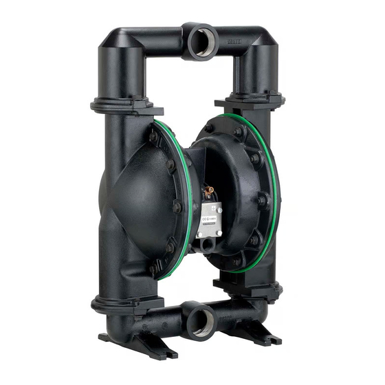
2" DIAPHRAGM PUMP
1:1 RATIO (METALLIC)
READ THIS MANUAL CAREFULLY BEFORE INSTALLING,
OPERATING OR SERVICING THIS EQUIPMENT.
The original language of this manual is English.
. . . . . . 85.3 db(A)
) to meet the intent of ANSI
Aeq
666250-XXX-C
MODEL DESCRIPTION CHART
Center Body Material / Fluid Connection
5 - Aluminum / 2 - 11-1/2 NPTF - 2
7 - Aluminum / Rp 2 (2 - 11 BSP parallel)
Fluid Cap & Manifold Material / Hardware
0 - Aluminum / Carbon steel
1 - Stainless Steel / Carbon Steel
2 - Cast Iron / Carbon Steel
A - Aluminum / Stainless Steel
B - Stainless Steel / Stainless Steel
C - Cast Iron / Stainless Steel
Seat Material
1 - Aluminum
8 - Hard Stainless Steel
2 - 316 Stainless Steel
9 - Hytrel
4 - Kynar PVDF
E - Santoprene
5 - Carbon Steel
G - Nitrile
Ball Material
2 - Nitrile
C - Hytrel
4 - PTFE
E - Santoprene
A - 316 Stainless Steel
Diaphragm Material
2 - Nitrile
9 - Hytrel
4 - PTFE / Santoprene
B - Santoprene
Fluid Section Service Kit Selection
Example: Model #666250-1EB-C
Fluid Section Service Kit # 637432-EB
RELEASED:
3-13-06
REVISED:
5-5-10
(REV. 07)
Figure 1
6662 X X - X X X - C
6662XX - X X X - C
637432 - X X
Ball
Diaphragm
Advertisement
Table of Contents

Related Manuals for Ingersoll-Rand ARO 666250 C Series


Summary of Contents for Ingersoll-Rand ARO 666250 C Series
- Page 1 OPERATOR’S MANUAL 666250-XXX-C INCLUDING: OPERATION, INSTALLATION & MAINTENANCE RELEASED: 3-13-06 REVISED: 5-5-10 (REV. 07) 2" DIAPHRAGM PUMP 1:1 RATIO (METALLIC) READ THIS MANUAL CAREFULLY BEFORE INSTALLING, OPERATING OR SERVICING THIS EQUIPMENT. It is the responsibility of the employer to place this information in the hands of the operator. Keep for future reference. The original language of this manual is English.
- Page 2 OPERATING AND SAFETY PRECAUTIONS READ, UNDERSTAND AND FOLLOW THIS INFORMATION TO AVOID INJURY AND PROPERTY DAMAGE. jury or property damage. Do not attempt to return a pump EXCESSIVE AIR PRESSURE HAZARDOUS MATERIALS to the factory or service center that contains hazardous STATIC SPARK HAZARDOUS PRESSURE material.
- Page 3 GENERAL DESCRIPTION MAINTENANCE The ARO diaphragm pump off ers high volume delivery even at low Refer to the part views and descriptions as provided on pages 4 air pressure and a broad range of material compatibility options are through 7 for parts identifi cation and service kit information. available.
- Page 4 PARTS LIST / 6662XX-XXX-C FLUID SECTION 637432-XX Fluid section service kit includes: Balls (see Ball Option, refer to -XX in chart below), Diaphragms (see Diaphragm Option, refer to -XX in chart below) and items 2 and 19 (listed below) plus 93706-1 Key-Lube grease packet (page 6). SEAT OPTIONS 6662XX-XXX-C BALL OPTIONS 6662XX-XXX-C “21”...
- Page 5 PARTS LIST / 6662XX-XXX-C FLUID SECTION COLOR CODE Diaphragm Ball Material Color Color Hytrel Cream Cream Nitrile Black Red (•) Santoprene Santoprene Green* N / A (backup) PTFE White White (-) Stripe (•) Dot * See item 8 in inset below. FOR THE AIR MO- Torque Sequence TOR SECTION, SEE...
- Page 6 PARTS LIST / 6662XX-XXX-C AIR MOTOR SECTION Indicates parts included in 637434 air section service kit. AIR MOTOR PARTS Item Description Qty Part No. Item Description Qty Part No. (size) (size) 101 Motor Body (1) 96374 116 Spacer (1) 96420 102 “O”...
- Page 7 PARTS LIST / 6662XX-XXX-C AIR MOTOR SECTION IMPORTANT BE CERTAIN TO ORIENT (115) SPACER LEGS AWAY FROM BLOCK- ING INTERNAL PORTS WHEN REASSEMBLING AIR SECTION. MAJOR VALVE See cross section detail, fi gure 4. Figure 3 PILOT VALVE MAJOR VALVE CROSS SECTION DETAIL 112 114 111 115 ASSEMBLY TORQUE REQUIREMENTS...
- Page 8 TROUBLE SHOOTING Product discharged from exhaust outlet. Check for kinked (restrictive) outlet material hose. Check for diaphragm rupture. Check for kinked (restrictive) or collapsed inlet material hose. Check tightness of (14) diaphragm screw. Check for pump cavitation - suction pipe should be sized at least as large as the inlet thread diameter of the pump for Air bubbles in product discharge.
Need help?
Do you have a question about the ARO 666250 C Series and is the answer not in the manual?
Questions and answers