Table of Contents
Advertisement
Quick Links
Advertisement
Table of Contents

Related Manuals for Cabletron Systems SEHI100TX-22


Summary of Contents for Cabletron Systems SEHI100TX-22
- Page 1 SEHI100TX-22 100BASE-T INTELLIGENT STACKABLE HUB USER’S GUIDE ®...
-
Page 3: Fcc Notice
Only qualified personnel should perform installation procedures. Cabletron Systems reserves the right to make changes in specifications and other information contained in this document without prior notice. The reader should in all cases consult Cabletron Systems to determine whether any such changes have been made. -
Page 4: Doc Notice
IMPORTANT: Before utilizing this product, carefully read this License Agreement. This document is an agreement between you, the end user, and Cabletron Systems, Inc. (“Cabletron”) that sets forth your rights and obligations with respect to the Cabletron software program (the “Program”) contained in this package. -
Page 5: United States Government Restricted Rights
Government is subject to restrictions as set forth in subparagraph (c) (1) (ii) of the Rights in Technical Data and Computer Software clause at 252.227-7013. Cabletron Systems, Inc., 35 Industrial Way, Rochester, New Hampshire 03867-0505. SEHI100TX User’s Guide... -
Page 6: Declaration Of Conformity
Principal Compliance Engineer ___________________________________ Title Rochester, NH, USA ___________________________________ Location 89/336/EEC 73/23/EEC Cabletron Systems, Inc. 35 Industrial Way PO Box 5005 Rochester, NH 03867 Mr. J. Solari Cabletron Systems Limited Nexus House, Newbury Business Park London Road, Newbury Berkshire RG13 2PZ, England... -
Page 7: Table Of Contents
CHAPTER 1 INTRODUCTION Using This Manual... 1-1 Document Conventions ... 1-2 Getting Help... 1-3 Related Manuals... 1-4 CHAPTER 2 SEHI FEATURES AND OPTIONS SEHI Overview ... 2-1 SEHI Features ... 2-2 Stackable Capabilities ... 2-3 Rack Mounting Capabilities ... 2-4 Remote Network Management... - Page 8 Testing the Installation ...5-5 CHAPTER 6 TROUBLESHOOTING Installation Test ...6-1 Using LANVIEW...6-2 Using the RESET Button ...6-4 Setting the NVRAM Switch ...6-5 CHAPTER 7 LOCAL MANAGEMENT Keyboard Conventions...7-2 Management Terminal Setup...7-3 Accessing Local Management ...7-6 The Feature Selection Screen ...7-8 The Community Name Table Screen...7-9...
- Page 9 The Device Statistics Screen... 7-24 7.9.1 Selecting the Appropriate Module/Port ... 7-27 7.9.2 Using the ENABLE PORT Command ... 7-27 7.9.3 Using the DISABLE PORT Command ... 7-27 7.9.4 Setting the UPDATE-FREQency Field ... 7-28 7.9.5 Exiting the Device Statistics Screen ... 7-28 APPENDIX A EPIM SPECIFICATIONS EPIM Specifications...A-1...
- Page 10 Contents viii SEHI100TX User’s Guide...
-
Page 11: Chapter 1 Introduction
Welcome to the Cabletron Systems SEHI100TX-22 100BASE-T Intelligent Stackable Hub User’s Guide. This manual provides installation instructions, troubleshooting, and reference information for the SEHI100TX-22. The term SEHI (Stackable Ethernet Hub with Intelligence) is NOTE used throughout this manual when describing the features and functions of the SEHI100TX-22. -
Page 12: Document Conventions
Management screens and the available commands. Appendix A, EPIM Specifications, provides specifications, cabling information, and switch settings for the Ethernet Port Interface Modules. Appendix B, Image File Download Using OID Strings, provides instructions for setting up a TFTP server and downloading an image file to the SEHI by setting specific MIB OID strings. -
Page 13: 1.3 Getting Help
• Network load and frame size at the time of trouble (if known) • The serial and revision numbers of all Cabletron Systems products in the network • The device history (i.e., have you returned the device before, is this a recurring problem, etc.) -
Page 14: Related Manuals
Chapter 1: Introduction RELATED MANUALS Use the Cabletron Systems SEH100TX-22 100BASE-T User’s Guide to supplement the procedures and other technical data provided in this manual. The procedures contained in the SEH100TX-22 100BASE-T User’s Guide are referenced where appropriate, but not repeated in this manual. -
Page 15: Sehi Features And Options
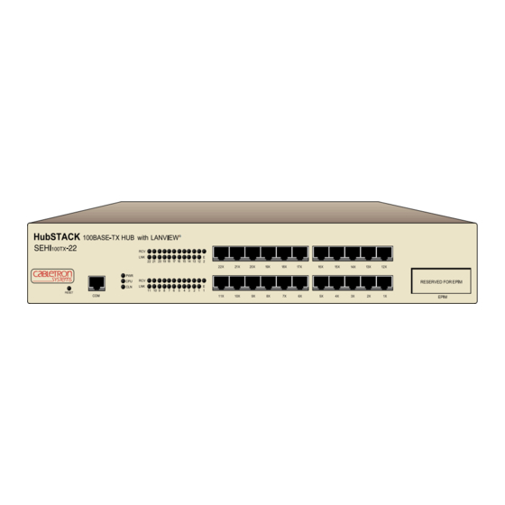
ADD. Power Supply SEHI OVERVIEW The SEHI100TX-22 is an intelligent repeating hub providing 22 RJ45 ports and one Ethernet Port Interface Module (EPIM) port on the front panel for network connections. The SEHI has two rear panel HubSTACK Interconnect Bus ports for stackable connections. The SEHI100TX-22 can manage up to four of Cabletron Systems SEH100TX-22 non-intelligent stackable hubs. -
Page 16: Sehi Features
SEHI transmits retimed data packets, regenerates the preamble, extends fragments, and arbitrates collisions. The SEHI100TX-22 meets IEEE 802.3u Repeater Class I standards. Class I standards allow one repeater between any two Data Terminal Equipment (DTE) devices within a single collision domain (network). -
Page 17: Lanview Leds
Local Management. STACKABLE CAPABILITIES The SEHI100TX-22 intelligent hub is designed to manage a stack of up to four Cabletron Systems SEH100TX-22 non-intelligent hubs. The SEHI is placed at the bottom of the stack. It manages all SEH hubs in the stack and provides full packet and error statistics for the entire stack, individual device, or individual port. -
Page 18: Rack Mounting Capabilities
Chapter 2: SEHI Features and Options RACK MOUNTING CAPABILITIES The SEHI can be installed in a 19-inch rack. Cabletron Systems provides brackets and mounting screws with the SEHI. See Chapter 4, Installation, for complete rack mounting instructions. REMOTE NETWORK MANAGEMENT Manage the SEHI remotely with any SNMP network management system. -
Page 19: Chapter 3 Installation Requirements And Specifications
Attach the SEHI to the stacked SEH modules with the HubSTACK Interconnect cables provided with each SEH and available only from Cabletron Systems (P/N 9380209). The cable attaches to the SEHI rear panel bus “OUT” port. The SEHI must be placed at the bottom of the stack. -
Page 20: Utp Cable Specifications
Chapter 3: Installation Requirements and Specifications 3.1.2 UTP Cable Specifications The device at the other end of the twisted pair segment must meet IEEE 802.3u 100BASE-T specifications. When connecting a 100BASE-TX Twisted Pair Segment to the SEHI twisted pair network ports and the EPIM-100TX module, the network must meet the following requirements: Length... -
Page 21: Multimode Fiber Optic Cable Specifications
3.1.3 Multimode Fiber Optic Cable Specifications The SEHI supports the Cabletron Systems EPIM-100FX and EPIM-100FMB. These EPIMs meet IEEE 802.3u standards. When connecting a fiber optic segment to the SEHI EPIM-100FX or EPIM-100FMB module, the network must meet the following... -
Page 22: Network Cable Lengths
Chapter 3: Installation Requirements and Specifications Propagation delay (collision delay) is the amount of time it takes data to travel from the sending device to the receiving device. Total propagation delay allowed for the entire network is 256 bit times (2.56 s) in one direction (5.12 s round trip). - Page 23 The maximum length of an individual UTP segment may be no more than 100 meters. CAUTION Table 3-1 Maximum Class I Network Cable Length Number Repeaters 200 m SEHI100TX User’s Guide SEHI100TX-22 Repeater Figure 3-1 Class I Network UTP & Multimode Multimode Fiber Fiber Optics...
-
Page 24: Network Port Specifications
Chapter 3: Installation Requirements and Specifications NETWORK PORT SPECIFICATIONS The SEHI network ports use shielded RJ45 connectors that support UTP cabling. Figure 3-2 shows the RJ45 pinouts. 1 2 3 4 5 6 7 8 1. Receive + 2. Receive - 3. -
Page 25: Operating Specifications
OPERATING SPECIFICATIONS The operating specifications for the SEHI100TX-22 are described in this section. Cabletron Systems reserves the right to change these specifications at any time without notice. 3.5.1 Power Supply Requirements The SEHI uses a universal power supply. The input requirements are listed in Table 3-2. -
Page 26: Physical Specifications
Chapter 3: Installation Requirements and Specifications Immunity This unit meets the immunity requirements of EN 50082-1 including IEC 801-2 (ESD), IEC 801-3 (Radiated Susceptibility), and IEC 801-4 (EFT/B). PHYSICAL SPECIFICATIONS This section details the physical specifications for the SEHI. Dimensions (H x W x D): Weight: 2.8 in x 17.0 in x 13.5 in (7.2 cm x 43.6 cm x 34.6 cm) -
Page 27: Chapter 4 Installation
Cabletron Systems includes a 3 1/2-inch disk with the NOTE SEHI100TX-22 that contains a backup copy of the FLASH Firmware Image File. Download the file to the SEHI100TX-22 if the existing image becomes corrupted. Refer to Appendix B for detailed download instructions. -
Page 28: Pre-Installation Checkout
DOWN position by looking in through the grillwork on the right side of the hub. If the switch is UP, move it into the DOWN position with a non-metallic tool. Do not remove the chassis cover to perform this operation. -
Page 29: Tabletop Or Shelf Installation
Proceed to Section 4.5, Powering Up and Stacking the SEHI. RACKMOUNT INSTALLATION To install the SEHI in a 19-inch rack, Cabletron Systems provides a kit with the SEHI that includes rackmount brackets, mounting screws, and a strain-relief bracket for cable management. - Page 30 Chapter 4: Installation Rack mounting the SEHI involves the following: • Attaching the strain-relief bracket • Rack mounting the SEHI • Stacking the SEHI when applicable Before installing the SEHI into a rack, ensure that the rack can support the device(s) without compromising the stability of the WARNING rack.
- Page 31 1. Remove the four cover screws (two from each side) located along the front edges of each side of the SEHI. Do not remove the cover from the SEHI100TX-22. Do not remove any other screws from the unit. 2. Using the four 6-32 x 3/8-inch replacement flathead cover screws provided in the rackmount kit, attach the rack mounting brackets to each side of the SEHI.
- Page 32 Chapter 4: Installation 3. Ensure that the rack used will support the unit, and that the rack will remain stable with the unit installed in it. Support the SEHI securely from underneath, and align the mounting brackets of the SEHI chassis with the screw holes in the equipment rack as shown in Figure 4-5.
-
Page 33: Powering Up And Stacking The Sehi
POWERING UP AND STACKING THE SEHI The following section details the procedures that must be followed to power up and interconnect stacked hubs. Failure to follow this procedure may result in damage to the equipment. CAUTION If you are using an intelligent hub (SEHI) to manage the stack, you must locate the SEHI at the bottom of the stack. - Page 34 Chapter 4: Installation 3. Power up the SEH above the SEHI in the stack by plugging the power cord into the back panel of the SEH and plugging the other end into a grounded receptacle. 4. Verify that the PWR LED is on, indicating that the SEH is receiving power.
-
Page 35: Installing An Epim
INSTALLING AN EPIM This section contains procedures on how to install the EPIM-100TX, EPIM-100FX, or the EPIM-100FMB to upgrade or change the capabilities of your SEHI. After installing a new EPIM, refer to the appropriate EPIM section in Appendix A to verify proper operation. Observe all static precautions while handling an EPIM. - Page 36 Chapter 4: Installation 4-10 SEHI100TX User’s Guide...
-
Page 37: Chapter 5 Connecting To The Network
CONNECTING TO THE NETWORK This chapter outlines the procedure for connecting the SEHI to a network. Ensure that the network meets the guidelines and requirements outlined in Chapter 3, Installation Requirements and Specifications, before installing the SEHI. CONNECTING THE SEHI TO THE NETWORK The procedure for connecting network segments to the SEHI varies depending on the media and ports being connected. -
Page 38: Connecting To An Epim-100Tx
Check the cable for continuity. d. Check that the twisted pair connection meets the cable specifications outlined in Section 3.1.2. If a link is not established, contact Cabletron Systems Technical Support. 5.1.2 Connecting to an EPIM-100TX The EPIM-100TX is often used to provide a connection between the SEHI and a bridge, router, or switch. - Page 39 Check that the twisted pair connection meets the cable specifications outlined in Section 3.1.2. e. Check that the crossover switch is in the correct position. If a link is not established, contact Cabletron Systems Technical Support. SEHI100TX User’s Guide Connecting the SEHI to the Network...
-
Page 40: Connecting To An Epim-100Fx Or Epim-100Fmb
Connecting to an EPIM-100FX or EPIM-100FMB The EPIM-100FX and EPIM-100FMB have an SC style network port (see Figure 5-3). Cabletron Systems supplies fiber optic cables using SC connectors that are keyed to ensure proper crossover of the transmit and receive fibers. -
Page 41: Testing The Installation
Verify that the fiber optic connection meets the dB loss specifications outlined in Section 3.1.3. If a link is not established, contact Cabletron Systems Technical Support. TESTING THE INSTALLATION The SEHI00TX-22 is now ready for operation. Before placing the network into service, test that all stations can be addressed and that the SEHI and all stations are indicating normal operation. - Page 42 Chapter 5: Connecting to the Network SEHI100TX User’s Guide...
-
Page 43: Chapter 6 Troubleshooting
This chapter contains instructions for using LANVIEW LEDs to troubleshoot physical layer network problems. It also describes how to reset the SEHI and how to reset the NVRAM switch. INSTALLATION TEST After connecting the SEHI to the network, verify that packets pass between all Ethernet devices connected to the SEHI and any other devices connected to the network. -
Page 44: Using Lanview
The affected port remains segmented until a good packet is transmitted/received without collisions. If the LNK LED is still not on, contact Cabletron Systems Technical Support. Refer to Section 1.3 for instructions about getting help. USING LANVIEW The SEHI incorporates the Cabletron Systems LANVIEW status monitoring and diagnostics system. - Page 45 HubSTACK 100BASE-TX HUB SEHI 100TX RESET LED NAME (Power) (Central Processing Unit) (Collision) (Receive) (Link) Flashing indicates an irregular LED pulse. NOTE Blinking indicates a steady LED pulse. When this green LED is on, it indicates that the SEHI is receiving power. If this LED is off, it indicates a loss of input power.
-
Page 46: Using The Reset Button
Chapter 6: Troubleshooting This LED alternates from red to green to during power up. After the boot is complete, the LED blinks green. A blinking green LED indicates normal operation. A red LED indicates a faulty processor. When this red LED flashes, it indicates that a collision has occurred on one of the ports. -
Page 47: Setting The Nvram Switch
SETTING THE NVRAM SWITCH To prevent the possibility of electrical shock, do not remove the chassis cover to access the NVRAM switch, and use only a non-metallic tool when moving the NVRAM switch. The SEHI uses NVRAM to store user-entered parameters such as IP address and Community Names. - Page 48 Chapter 6: Troubleshooting SEHI100TX User’s Guide...
-
Page 49: Chapter 7 Local Management
LOCAL MANAGEMENT This chapter explains how to set up a management terminal to access the SEHI Local Management. It also explains how to use the Local Management screens and commands. Local Management supplies the tools to manage the SEHI and all of its attached segments. -
Page 50: Keyboard Conventions
Chapter 7: Local Management KEYBOARD CONVENTIONS All key names appear in this manual as capital letters. For example, the enter (return) key appears as ENTER and the space bar appears as SPACE bar. Table 7-1 explains the keyboard conventions used in this manual as well as the key functions. -
Page 51: Management Terminal Setup
MANAGEMENT TERMINAL SETUP Use one of the following systems to access Local Management: • A Digital Equipment Corporation VT series terminal • A VT type terminal running emulation programs for the Digital Equipment Corporation VT series • An IBM or compatible PC running a VT series emulation software package An RJ45 console cable is required to attach the management terminal to the SEHI. - Page 52 Chapter 7: Local Management Console Cable Configuration Use the RJ45 Cable Kit provided with the SEHI to attach the management terminal to the SEHI COM port as shown in Figure 7-1. Connect the console cable to the SEHI as follows: 1.
- Page 53 Management Terminal Setup Parameters Table 7-2 lists the setup parameters for the local management terminal. If the terminal is a Digital Equipment Corporation VT320 terminal, press F3 to access the Setup Directory. If the local management terminal uses terminal emulation of the VT320, refer to the equipment user manual for setup procedures.
-
Page 54: Accessing Local Management
SEHI, access the Local Management interface. Use the following steps to access Local Management: 1. Power up the terminal. The Password screen (Figure 7-2) appears. (c) Copyright Cabletron Systems, Inc. 1993 Enter User Password: 2. Enter the Password. The factory default password for Super-User access is “public”... - Page 55 3. Press ENTER. • If the password entry is invalid, the cursor returns to the beginning of the password entry field. • If the password is valid, the associated access privilege appears briefly, then the Feature Selection screen (Figure 7-3) appears. If the terminal keyboard is not used for 15 minutes, the Local NOTE Management session ends and the screen defaults to the...
-
Page 56: The Feature Selection Screen
To exit your Local Management session, use the arrow keys to highlight the EXIT LIM SERVICE command, then press ENTER. P .O. Box 5005 Rochester, NH 03867-0505 U.S.A. Figure 7-3 Feature Selection Screen SEHI LOCAL MANAGEMENT Cabletron Systems Incorporated (603) 332-9400 FEATURE SELECTION COMMUNITY NAME TABLE IP ADDRESS ASSIGNMENT... -
Page 57: The Community Name Table Screen
THE COMMUNITY NAME TABLE SCREEN To access the Community Name Table screen from the Feature Selection screen, use the arrow keys to highlight the Community Name Table option, then press ENTER or F6. The Community Name Table screen shown in Figure 7-4 appears. COMMUNITY NAME PUBLIC PUBLIC... -
Page 58: Community Name
Chapter 7: Local Management The following sections explain each field on the Community Name Table screen and provides instructions on how to change them. COMMUNITY NAME Displays the user-defined name through which a user can access Local Management for the SEHI. Any community name assigned here acts as a password to Local Management. -
Page 59: Editing The Community Name Field
7.5.1 Editing the Community Name Field The password used to access Local Management at the Password screen must have Super-User privileges for the edits to take effect. If a password is entered with Basic-Read, Read-Only, or Read-Write privileges, Local Management displays the message “AUTHORIZATION PROHIBITS ACCESS”, and does not include editing capabilities. -
Page 60: The Configuration Screen
Chapter 7: Local Management THE CONFIGURATION SCREEN To access the Configuration screen from the Feature Selection screen, use the arrow keys to highlight the IP Address Assignment option, then press ENTER or F7. The screen shown in Figure 7-5 appears. IP Address 000.000.000.000 Serial Port 1 Application: CONSOLE... -
Page 61: Setting The Ip Address
IP Address Displays the IP address of the SEHI. SubNET Mask Displays the subnet mask for the SEHI. A subnet mask is a 32-bit quantity which “masks out” the network bits of the IP address. This is done by setting the bits in the mask to 1 when the network treats the corresponding bits in the IP address as part of the network or subnetwork address, or to 0 if the corresponding bit identifies the host. -
Page 62: Setting The Subnet Mask
Chapter 7: Local Management 4. Use the arrow keys to highlight the SAVE option, then press ENTER or F6. The “SAVED OK” message appears indicating that the changes have been saved to memory. The first time an attempt is made to exit the screen without NOTE saving the changes, a “NOT SAVED?”... -
Page 63: Setting The Default Gateway
The first time an attempt is made to exit the screen without NOTE saving the changes, a “NOT SAVED?” message is displayed. The edits are lost if the user proceeds to exit without saving the changes. 7.6.3 Setting the Default Gateway The Default Gateway field allows the user to describe the router through which the SEHI will be forwarding IP packets. -
Page 64: The Trap Table Screen
Chapter 7: Local Management 1. Press the appropriate Function key. To return to the Feature Selection screen, use the arrow keys to highlight the RETURN command. 2. Press ENTER. The Feature Selection screen appears. THE TRAP TABLE SCREEN Access the Trap Table screen from the Feature Selection screen using the arrow keys to highlight the Component Trap Table option, then press ENTER or F8. -
Page 65: Configuring The Trap Table
SNMP Community Name Displays the community name included in the trap message sent to the Network Management Station with the associated IP address. Traps Enables transmission of the traps to the network management station with the associated IP address. Trap IP Address Indicates the IP address of the workstation to receive trap alarms from the SEHI. -
Page 66: Exiting The Trap Table Screen
Chapter 7: Local Management 7.7.2 Exiting the Trap Table Screen Use the following steps to exit the Trap Table screen and return to the Feature Selection screen: 1. Press the appropriate Function key. To exit to the Feature Selection screen, use the arrow keys to highlight the RETURN command. 2. -
Page 67: Snmp Community Name
GETNEXT The following sections describe SNMP Tools screen fields. SNMP COMMUNITY NAME Identifies the community name used as a password to determine access level to the MIB component. OID PREPEND Specifies the number prefix common to all Object Identifiers (OIDs) found in the MIBs –... -
Page 68: Getting Individual Oids
Chapter 7: Local Management GETNEXT Displays the OID following the current OID. WALK Allows the user to scroll through a section of the MIB leaf by leaf, from a user-specified object identifier. Leaves are the sections of the OID separated by periods. When a walk is initialized, the following categories for each walk entry, or step are displayed. -
Page 69: Getting The Next Oid
• Enter an “=” and the OID suffix (e.g., if =4.1.3 is entered, then the OID=4.1.3). This allows the user to not use the prepend. • Press F9 to recall an OID already entered. The user can then use the keyboard to modify the recalled OID as necessary. 3. -
Page 70: Viewing Multiple Oids
Chapter 7: Local Management 3. Press ENTER. If there is no instance of that OID, the return code will specify “MIB_NO_INSTANCE”, otherwise “DATA TYPE:” appears. 4. Enter the data type for that OID. The following are possible choices: integer, string, null, OID, IP address, counter, gauge, timeticks, and opaque. -
Page 71: Stepping Through Oids
7.8.6 Stepping Through OIDs Use the following steps to STEP through OIDs (the user can step through only after a GETNEXT): 1. Highlight STEP, using the arrow keys, then press ENTER. “Specify OID” appears. 2. Enter the OID (only the suffix is necessary) and press ENTER. The Tools screen begins to scroll one OID at a time, through all of the sublayers of the MIB available for that OID. -
Page 72: The Device Statistics Screen
Chapter 7: Local Management THE DEVICE STATISTICS SCREEN This section describes the features of the Device Statistics screen. The user can view error, collision, and traffic statistics for the stack, a selected module, or a selected port. The user can also enable and disable ports. To access the Device Statistics screen from the Feature Selection screen, use the arrow keys to highlight the Device Statistics option, then press ENTER. - Page 73 ERRORS RECEIVED Displays the number of errors received. COLLISIONS Displays the number of collisions received. OOW COLLISIONS Displays the number of Out Of Window collisions. OOW collisions are usually caused by one or more of the following: • The network being too long due to the round trip propagation delay being greater than 5.12 s (the collision domain is too large).
-
Page 74: Enable Port
Chapter 7: Local Management PORT SEG. STATUS Displays the segmentation status of the port selected. The two possible status messages are Segmented or Unsegmented. The SEHI and SEH automatically partition problem segments, and reconnect non-problem segments to the network. ENABLE PORT This command lets the user enable the selected port. -
Page 75: Selecting The Appropriate Module/Port
7.9.1 Selecting the Appropriate Module/Port When the Device Statistics screen first appears, statistics are displayed for Module 1 and Port 1. View statistics for another module and port by using the Module x or Port x commands at the bottom of the screen. Use the following steps to select a module or port: 1. -
Page 76: Setting The Update-Freqency Field
Chapter 7: Local Management 7.9.4 Setting the UPDATE-FREQency Field This field changes the time interval between Stack/Module/Port counter updates. Use the following steps to set the update frequency: 1. Use the arrow keys to highlight the UPDATE-FREQ command at the bottom of the screen. -
Page 77: A.1 Epim Specifications
The slide switch on the EPIM-100TX determines the crossover status of the cable pairs. If the switch is on the X side, the pairs are internally crossed over. If the switch is on the = side, the pairs are not internally crossed over. -
Page 78: A.1.2 Epim-100Fx
Appendix A: EPIM Specifications A.1.2 EPIM-100FX The EPIM-100FX shown in Figure A-2 supports Multimode Fiber Optic cabling. The EPIM-100FX is equipped with an SC style connector. Specifications for the EPIM-100FX are listed in Table A-1. 1511_17 Table A-1 Transmitter Power (EPIM-100FX) Cable Type 50/125 m fiber optic 62.5/125 m fiber optic... -
Page 79: A.1.3 Epim-100Fmb
The maximum diameter of a 100BASE-T collision domain using UTP cable to the desktop and fiber cable in the next domain or switch port is only 263 meters (100 meters of UTP and 163 meters of fiber optics). - Page 80 Appendix A: EPIM Specifications The transmitter power levels and receive sensitivity levels listed are peak power levels after optical overshoot. A peak power meter must be used to correctly compare the values given above to those measured on any particular port. If power levels are being measured with an average power meter, add 3 dBm to the measurement to compare the measured values to the values listed above.
- Page 81 IMAGE FILE DOWNLOAD USING OID STRINGS This appendix provides instructions for setting up a TFTP server and to download an image file to the SEHI by setting specific MIB OID strings. Set the OID strings with the SNMP Tools screen described in Chapter 7. Download an image file to the SEHI with a remote NOTE management package such as SPECTRUM, SPECTRUM...
-
Page 82: Appendix Bimage File Download Using Oid Strings
Appendix B: Image File Download Using OID Strings SETTING UNIX WORKSTATION AS TFTP SERVER Downloading an image file requires setting up your UNIX workstation as a TFTP server. Due to variations between UNIX systems, and individual NOTE configurations, this section provides only GUIDELINES for configuring a UNIX workstation to perform an image file download. -
Page 83: Standard Local Download
MIB walking tool documentation for instructions on how to set MIB OID strings. The Download OIDs for Cabletron Systems products reside in the Cabletron Systems enterprise MIBs (group 52). The specific OIDs necessary to perform an image file download reside in the common download group under ctDL (Cabletron Download). - Page 84 Appendix B: Image File Download Using OID Strings Step OID Name ctDLForceOnBoot ctDLCommitRAMToFlash ctDLTFTPRequestHost ctDLTFTPRequest ctDLInitiateColdBoot Table B-1 OIDs and Settings OID Number 1.3.6.1.4.1.52.4.1.5.8.1.1.0 1.3.6.1.4.1.52.4.1.5.8.1.2.0 1.3.6.1.4.1.52.4.1.5.8.1.4.0 1.3.6.1.4.1.52.4.1.5.8.1.5.0 1.3.6.1.4.1.52.4.1.5.8.1.3.0 Data SNMP OID Type Data integer integer Enter the IP address address of the TFTP server.
- Page 85 Numerics 100BASE-TX cable length 3-2 crosstalk 3-2 impedance 3-2 jitter 3-2 noise 3-2 propagation delay 3-3 temperature 3-3 Agency approvals emissions 3-7 immunity 3-7 safety 3-7 Cable specifications 3-1 multimode fiber optic 3-3 UTP and STP 3-2 Caution 1-2 COM port 3-6 Community Name Table access 7-10 community name 7-10...
- Page 86 Multimode fiber optic cable specifications 3-3 Network connection EPIM-100FMB 5-4 EPIM-100FX 5-4 EPIM-100TX 5-2 SEH100TX-22 5-1 Network port specifications SEHI100TX-22 3-6 NVRAM setting 6-5 OIDs 7-18 Operating specifications 3-7 Index-2 Port ENABLE override 7-15 Power supply requirements 3-7 Remote network management 2-4...
-
Page 87: Power Supply Cord
POWER SUPPLY CORD The mains cord used with this equipment must be a 2 conductor plus ground type with minimum 0.75 mm square conductors and must incorporate a standard IEC appliance coupler on one end and a mains plug on the other end which is suitable for the use and application of the product and that is approved for use in the country of application.
Need help?
Do you have a question about the SEHI100TX-22 and is the answer not in the manual?
Questions and answers