Table of Contents
Advertisement
Quick Links
Advertisement
Table of Contents

Related Manuals for Cabletron Systems SEHI SEHI100TX-


Summary of Contents for Cabletron Systems SEHI SEHI100TX-
- Page 1 SEHI100TX-22 100BASE-T INTELLIGENT STACKABLE HUB USER’S GUIDE ®...
- Page 2 NOTICE Cabletron Systems reserves the right to make changes in specifications and other information contained in this document without prior notice. The reader should in all cases consult Cabletron Systems to determine whether any such changes have been made. The hardware, firmware, or software described in this manual is subject to change without notice.
-
Page 3: Fcc Notice
Notice FCC NOTICE This device complies with Part 15 of the FCC rules. Operation is subject to the following two conditions: (1) this device may not cause harmful interference, and (2) this device must accept any interference received, including interference that may cause undesired operation. NOTE: This equipment has been tested and found to comply with the limits for a Class A digital device, pursuant to Part 15 of the FCC rules. - Page 4 IMPORTANT: Before utilizing this product, carefully read this License Agreement. This document is an agreement between you, the end user, and Cabletron Systems, Inc. (“Cabletron”) that sets forth your rights and obligations with respect to the Cabletron software program (the “Program”) contained in this package.
-
Page 5: United States Government Restricted Rights
Government is subject to restrictions as set forth in subparagraph (c) (1) (ii) of the Rights in Technical Data and Computer Software clause at 252.227-7013. Cabletron Systems, Inc., 35 Industrial Way, Rochester, New Hampshire 03867-0505. SEHI100TX User’s Guide... -
Page 6: Table Of Contents
CHAPTER 1 INTRODUCTION Using This Manual... 1-1 Document Conventions ... 1-2 Getting Help... 1-3 Related Manuals... 1-3 CHAPTER 2 SEHI FEATURES AND OPTIONS SEHI Overview ... 2-1 SEHI Features ... 2-2 Stackable Capabilities ... 2-3 Rack Mounting Capabilities ... 2-4 Remote Network Management... - Page 7 Testing the Installation ...5-5 CHAPTER 6 TROUBLESHOOTING Installation Test ...6-1 Using LANVIEW...6-2 Using the RESET Button ...6-4 Setting the NVRAM Switch ...6-5 CHAPTER 7 LOCAL MANAGEMENT Local Management Keyboard Conventions ...7-2 Management Terminal Setup...7-3 Accessing Local Management ...7-6 The Feature Selection Screen ...7-7 The Community Name Table Screen...7-8...
- Page 8 The Device Statistics Screen... 7-21 7.9.1 Selecting the Appropriate Module/Port ... 7-23 7.9.2 Using the ENABLE PORT Command ... 7-24 7.9.3 Using the DISABLE PORT Command ... 7-24 7.9.4 Exiting the Device Statistics Screen ... 7-24 APPENDIX A EPIM SPECIFICATIONS EPIM Specifications...A-1 A.1.1 EPIM-100TX...A-1...
-
Page 9: Chapter 1 Introduction
Welcome to the Cabletron Systems SEHI100TX-22 100BASE-T Intelligent Stackable Hub User’s Guide. This manual provides installation instructions, troubleshooting, and reference information for the SEHI100TX-22. The term SEHI (Stackable Ethernet Hub with Intelligence) is NOTE used throughout this manual when describing the features and functions of the SEHI100TX-22. -
Page 10: Document Conventions
Chapter 1: Introduction Appendix A, EPIM Specifications, provides specifications, cabling information, and switch settings for the Ethernet Port Interface Modules. Appendix B, Image File Download Using OIDs, provides instructions for setting up a TFTP server and downloading an image file to the SEHI by setting specific MIB OID strings. -
Page 11: 1.3 Getting Help
• Network load and frame size at the time of trouble (if known) • The serial and revision numbers of all Cabletron Systems products in the network • The device history (i.e., have you returned the device before, is this a recurring problem, etc.) -
Page 12: Chapter 2 Sehi Features And Options
Ethernet Port Interface Module (EPIM) port on the front panel for network connections. The SEHI has two rear panel HubSTACK Interconnect Bus ports for stackable connections. The SEHI100TX-22 is designed to manage the Cabletron Systems non-intelligent stackable hub, the SEH100TX-22. SEHI100TX User’s Guide... -
Page 13: Sehi Features
CAUT ION environment. Connect the SEHI100TX-22 and SEH100TX-22 only to similar 100BASE-T products. The SEHI100TX-22 supports the EPIM-100TX and the EPIM-100FX. No other Cabletron Systems EPIMs operate in this device. SEHI FEATURES Repeater Functionality The SEHI fully conforms to the IEEE 802.3u Repeater specifications. The SEHI transmits retimed data packets, regenerates the preamble, extends fragments, and arbitrates collisions. -
Page 14: Lanview Leds
STACKABLE CAPABILITIES The SEHI100TX-22 intelligent hub is designed to manage a stack of up to four Cabletron Systems SEH100TX-22 non-intelligent hubs. The SEHI is placed at the bottom of the stack. It manages all SEH hubs in the stack and provides full packet and error statistics for the entire stack, individual device, or individual port. -
Page 15: Rack Mounting Capabilities
Chapter 2: SEHI Features and Options RACK MOUNTING CAPABILITIES The SEHI can be installed in a 19-inch rack. Cabletron Systems provides brackets and mounting screws with the SEHI. See Chapter 4, Installation, for complete rack mounting instructions. REMOTE NETWORK MANAGEMENT Manage the SEHI remotely with any SNMP network management system. -
Page 16: Chapter 3 Installation Requirements And Specifications
Attach the SEHI to the stacked SEH modules with the HubSTACK Interconnect cables provided with each SEH and available only from Cabletron Systems (P/N 9380209). The cable attaches to the SEHI rear panel bus “OUT” port. The SEHI must be placed at the bottom of the stack. -
Page 17: Utp Cable Specifications
Chapter 3: Installation Requirements and Specifications 3.1.2 UTP Cable Specifications The device at the other end of the twisted pair segment must meet IEEE 802.3u 100BASE-T specifications. When connecting a 100BASE-TX Twisted Pair Segment to the SEHI twisted pair network ports and the EPIM-100TX module, the network must meet the following requirements: Length... -
Page 18: Multimode Specifications For The Epim-100Fx
3.1.3 Multimode Specifications for the EPIM-100FX The SEHI supports the Cabletron Systems EPIM-100FX. The EPIM-100FX meets IEEE 802.3u standards. When connecting a fiber optic segment to the SEHI EPIM-100FX module, the network must meet the following requirements: Cable Loss Test the fiber optic cable with a fiber optic attenuation test set adjusted for... -
Page 19: Network Cable Lengths
Chapter 3: Installation Requirements and Specifications NETWORK CABLE LENGTHS This section details the maximum network cable lengths specified by the IEEE 802.3u standard for a Class I repeater. As stated previously, the physical size of the network is limited primarily by propagation delay. The round trip delay cannot exceed 512 bit times or 5.12 s. -
Page 20: Network Port Specifications
NETWORK PORT SPECIFICATIONS The SEHI network ports use shielded RJ45 connectors that support UTP cabling. Figure 3-2 shows the RJ45 pinouts. 1 2 3 4 5 6 7 8 Figure 3-2 RJ45 Network Ports COM PORT REQUIREMENTS The RJ45 COM port supports access to a Local Management Console. The COM port supports a Digital Equipment Corporation VT320 terminal or PC emulation of the VT320 terminal. -
Page 21: Operating Specifications
3. Data Set Ready 4. Receive Data OPERATING SPECIFICATIONS The operating specifications for the SEHI100TX-22 are described in this section. Cabletron Systems reserves the right to change these specifications at any time without notice. 3.5.1 Power Supply Requirements The SEHI uses a universal power supply. The input requirements are listed in Table 3-2. -
Page 22: Agency Approvals
AGENCY APPROVALS The safety, emission, and immunity approvals for the SEHI are detailed in this section. Safety This unit meets the safety requirements of UL 1950, CSA C22.2 No. 950, IEC 950 and EN 60950. Emissions This unit meets the emission requirements of FCC Part 15 Class A, EN 55022 Class A and VCCI Class I. -
Page 23: Chapter 4 Installation
3. Visually inspect the SEHI. If there are any signs of damage, contact Cabletron Systems Technical Support immediately. 4. Read the SEHI Release Notes included in the shipping box. Cabletron Systems includes a 3-1/2" disk with the NOTE SEHI100TX-22 that contains a backup copy of the FLASH Firmware Image File. -
Page 24: Pre-Installation Checkout
DOWN position by looking in through the grillwork on the right side of the hub. If the switch is UP, move it into the DOWN position with a non-metallic tool. Do not remove the chassis cover to perform this operation. -
Page 25: Tabletop Or Shelf Installation
TABLETOP OR SHELF INSTALLATION This section provides guidelines for installation on a tabletop or shelf. Tabletop and shelf installations must be within reach of the network cabling and meet the requirements listed below: • In a shelf installation, the shelf must be able to support 30 pounds of static weight for each device in the stack. -
Page 26: Rackmount Installation
Chapter 4: Installation RACKMOUNT INSTALLATION To install the SEHI in a 19-inch rack, Cabletron Systems provides a kit with the SEHI that includes rackmount brackets, mounting screws, and a strain-relief bracket for cable management. Rack mounting the SEHI involves the following: •... - Page 27 Rack Mounting the SEHI Refer to Figure 4-4 and proceed as follows to install the SEHI into a 19-inch rack. 1. Remove the four cover screws (two from each side) located along the front edges of each side of the SEHI. Do not remove the cover from the SEHI100TX-22.
- Page 28 Chapter 4: Installation 3. Ensure that the rack used will support the unit, and that the rack will remain stable with the unit installed in it. Support the SEHI securely from underneath, and align the mounting brackets of the SEHI chassis with the screw holes in the equipment rack as shown in Figure 4-5.
-
Page 29: Powering Up And Stacking The Sehi
POWERING UP AND STACKING THE SEHI The following section details the procedures that must be followed to power up and interconnect stacked hubs. Failure to follow this procedure may result in damage to the equipment. If you are using an intelligent hub (SEHI) to manage the stack, you must locate the SEHI at the bottom of the stack. - Page 30 Chapter 4: Installation 4. Verify that the PWR LED is on, indicating that the SEH is receiving power. Do NOT connect the interconnect cable between the SEH and the SEHI before powering up the SEH. Otherwise damage to CAUT ION the SEH may result.
-
Page 31: Installing The Epim-100Tx Or The Epim-100Fx
INSTALLING THE EPIM-100TX OR THE EPIM-100FX This section contains procedures on how to install the EPIM-100TX or the EPIM-100FX to upgrade or change the capabilities of your SEHI. After installing a new EPIM, refer to the appropriate EPIM section in Appendix A to verify proper operation. -
Page 32: Chapter 5 Connecting To The Network
CONNECTING TO THE NETWORK This chapter outlines the procedure for connecting the SEHI to a network. Ensure that the network meets the guidelines and requirements outlined in Chapter 3, Installation Requirements and Specifications, before installing the SEHI. CONNECTING THE SEHI TO THE NETWORK The procedure for connecting network segments to the SEHI varies depending on the media and ports being connected. -
Page 33: Connecting A Utp Segment To An Epim-100Tx
Check the cable for continuity. c. Check that the twisted pair connection meets dB loss and cable specifications outlined Chapter 2. If a link is not established, contact Cabletron Systems Technical Support. 5.1.2 Connecting a UTP Segment to an EPIM-100TX The EPIM-100TX is often used to provide a connection between the SEHI and a bridge, router, or switch. - Page 34 Check that the twisted pair connection meets dB loss and cable specifications outlined in Chapter 3, Section 3.1.2. e. Check that the crossover switch is in the correct position. If a link is not established, contact Cabletron Systems Technical Support. SEHI100TX User’s Guide Connecting the SEHI to the Network...
-
Page 35: Connecting A Fiber Segment To The Epim-100Fx
Connecting a Fiber Segment to the EPIM-100FX The EPIM-100FX has an SC style network port (see Figure 5-3). Cabletron Systems supplies fiber optic cables using SC connectors that are keyed to insure proper crossover of the transmit and receive fibers. -
Page 36: Testing The Installation
Verify that the fiber connection meets the dB loss specifications outlined in Chapter 3. If a link is not established, contact Cabletron Systems Technical Support. TESTING THE INSTALLATION The SEHI00TX-22 is now ready for operation. Before placing the network into service, test that all stations can be addressed and that the SEHI and all stations are indicating normal operation. -
Page 37: Chapter 6 Troubleshooting
This chapter contains instructions for using LANVIEW LEDs to troubleshoot physical layer network problems. It also describes how to reset the SEHI and how to reset the NVRAM switch. INSTALLATION TEST After connecting the SEHI to the network, verify that packets pass between all Ethernet devices connected to the SEHI and any other devices connected to the network. -
Page 38: Using Lanview
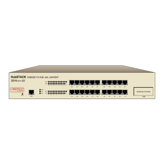
The affected port remains segmented until a good packet is transmitted/received without collisions. If the LNK LED is still not on, contact Cabletron Systems Technical Support. USING LANVIEW The SEHI incorporates the Cabletron Systems LANVIEW status monitoring and diagnostics system. - Page 39 HubSTACK 100BASE-TX HUB SEHI 100TX RESET LED NAME (Power) (Central Processing Unit) (Collision) (Receive) (Link) Flashing indicates an irregular LED pulse. NOTE Blinking indicates a steady LED pulse. When this green LED is on, it indicates that the SEHI is receiving power. If this LED is off, it indicates a loss of input power.
-
Page 40: Using The Reset Button
Chapter 6: Troubleshooting This red LED indicates that a collision has occurred on one of the ports. When a yellow RCV LED flashes, it indicates that the SEHI is receiving data packets from the associated port segment. Each SEHI port has a corresponding RCV LED: •... -
Page 41: Setting The Nvram Switch
SETTING THE NVRAM SWITCH To prevent the possibility of electrical shock, do not remove the chassis cover to access the NVRAM switch, and use only a non-metallic tool when moving the NVRAM switch. The SEHI uses NVRAM (Non-Volatile Random Access Memory) to store user-entered parameters such as IP address and Community Names. -
Page 42: Chapter 7 Local Management
LOCAL MANAGEMENT This chapter explains how to set up a management terminal to access the SEHI Local Management. It also explains how to use the Local Management screens and commands. Local Management supplies the tools to manage the SEHI and all of its attached segments. -
Page 43: Local Management Keyboard Conventions
Chapter 7: Local Management LOCAL MANAGEMENT KEYBOARD CONVENTIONS All key names appear in this manual as capital letters. For example, the enter (return) key appears as ENTER and the space bar appears as SPACE bar. Table 7-1 explains the keyboard conventions used in this manual as well as the key functions. -
Page 44: Management Terminal Setup
MANAGEMENT TERMINAL SETUP Use one of the following systems to access Local Management: • A Digital Equipment Corporation VT series terminal • A VT type terminal running emulation programs for the Digital Equipment Corporation VT series • An IBM or compatible PC running a VT series emulation software package An RJ45 console cable is required to attach the management terminal to the SEHI. - Page 45 Chapter 7: Local Management Console Cable Configuration Use the RJ45 Cable Kit provided with the SEHI to attach the management terminal to the SEHI COM port as shown in Figure 7-1. Connect the console cable to the SEHI as follows: 1.
- Page 46 Management Terminal Setup Parameters Table 7-2 lists the setup parameters for the local management terminal. If the terminal is a Digital Equipment Corporation VT320 terminal, press F3 to access the Setup Directory. If the local management terminal uses terminal emulation of the VT320, refer to the equipment user manual for setup procedures.
-
Page 47: Accessing Local Management
Cabletron SEHI Revision X.XX.XX Cabletron Systems Incorporated 35 Industrial Way, P .O. Box 5005 Rochester, NH 03867-0505 U.S.A. (603) 332-9400 (c) Copyright Cabletron Systems, Inc. 1993 SEHI F/W Version: X.XX.XX Boot Prom Version: X.XX.XX SEHI Board Version: X.X EnterUser Password:... -
Page 48: The Feature Selection Screen
EXIT LIM SERVICE command, then press ENTER. Figure 7-3 Feature Selection Screen SEHI100TX User’s Guide The Feature Selection Screen SEHI LOCAL MANAGEMENT Cabletron Systems Incorporated P .O. Box 5005 Rochester, NH 03867-0505 U.S.A. (603) 332-9400 FEATURE SELECTION COMMUNITY NAME TABLE... -
Page 49: The Community Name Table Screen
Chapter 7: Local Management THE COMMUNITY NAME TABLE SCREEN To access the Community Name Table screen from the Feature Selection screen, use the arrow keys to highlight the Community Name Table option, then press ENTER or F6. The Community Name Table screen shown in Figure 7-4 appears. -
Page 50: Editing The Community Name Field
ACCESS Indicates the access status accorded each community name. The following conditions are possible: Basic-Read Read-Only Read-Write Super-User 7.5.1 Editing the Community Name Field The password used to access Local Management at the Password screen must have Super-User privileges for the edits to take effect. If a password is entered with Basic-Read, Read-Only, or Read-Write privileges, Local Management displays the message “AUTHORIZATION PROHIBITS ACCESS”, and does not include editing capabilities. -
Page 51: The Configuration Screen
Chapter 7: Local Management The first time a user attempts to exit the screen without saving NOTE the changes, a “NOT SAVED?” message is displayed. The edits are lost if the user proceeds to exit without saving the changes. 6. To exit the screen, press the appropriate Function key or use the arrow keys to highlight the RETURN command. - Page 52 The Configuration Screen The number of the interface corresponding to the channels over which packets with that IP Address pass. On the SEHI, this value is always 1. IP Address Displays the IP address of the SEHI. SubNET Mask Displays the subnet mask for the SEHI. A subnet mask is a 32-bit quantity which “masks out”...
-
Page 53: Setting The Ip Address
Chapter 7: Local Management 7.6.1 Setting the IP Address Use the following steps to set the IP address: 1. Use the arrow keys to highlight the IP Address field. 2. Enter the IP address into this field. The format for this entry is XXX.XXX.XXX.XXX, with values for XXX being from 0 to 255. -
Page 54: Setting The Default Gateway
2. Enter the subnet mask into this field. The format for this entry is XXX.XXX.XXX.XXX with values for XXX being from 0 to 255. 3. Press ENTER. 4. Use the arrow keys to highlight the SAVE option, then press ENTER or F6. -
Page 55: Exiting The Configuration Screen
Chapter 7: Local Management 7.6.5 Exiting the Configuration Screen Use the following steps to exit the Configuration screen and return to the Feature Selection screen: 1. Press the appropriate Function key. To return to the Feature Selection screen, use the arrow keys to highlight the RETURN command. 2. -
Page 56: Configuring The Trap Table
Traps Enables transmission of the traps to the network management station with the associated IP address. Trap IP Address Indicates the IP address of the workstation to receive trap alarms from the SEHI. 7.7.1 Configuring the Trap Table Use the following steps to configure the Trap Table: 1. -
Page 57: The Snmp Tools Screen
Chapter 7: Local Management THE SNMP TOOLS SCREEN This section describes how to use the SNMP Tools screen to access Management Information Bases (MIBs). Access to screen options depends on the access status accorded to the user’s community name. This section describes Super-User management capabilities. SNMP Tools allows access to valuable MIB information. -
Page 58: Oid Prepend
OID PREPEND Specifies the number prefix common to all Object Identifiers (OIDs) found in the MIBs – 1.3.6.1 is the default prefix OID. This is a modifiable field. Lets you retrieve MIB objects using SNMP protocol. Allows users with Read-Write and Super-User access to change modifiable MIB objects, using SNMP protocol. -
Page 59: Getting Individual Oids
Chapter 7: Local Management 7.8.1 Getting Individual OIDs Use the following steps to GET an OID: 1. Highlight GET, using the arrow keys, then press ENTER or F6. “<GET> OID (=|F9)” appears. 2. Use one of the following options to enter the OID: •... -
Page 60: Viewing Multiple Oids
3. Press ENTER. If there is no instance of that OID, the return code will specify “MIB_NO_INSTANCE”, otherwise “DATA TYPE:” appears. 4. Enter the data type for that OID. The following are possible choices: integer, string, null, OID, IP address, counter, gauge, timeticks, and opaque. -
Page 61: Stepping Through Oids
Chapter 7: Local Management 7.8.6 Stepping Through OIDs Use the following steps to STEP through OIDs (the user can step through only after a GETNEXT): 1. Highlight STEP, using the arrow keys, then press ENTER. “Specify OID” appears. 2. Enter the OID (only the suffix is necessary) and press ENTER. The Tools screen will begin to scroll one OID at a time, through all of the sublayers of the MIB available for that OID. -
Page 62: The Device Statistics Screen
THE DEVICE STATISTICS SCREEN This section describes the features of the Device Statistics screen. The user can view error, collision, and traffic statistics for the stack, a selected module, or a selected port. The user can also enable and disable ports. To access the Statistics screen from the Features Selection screen, use the arrow keys to highlight the Device Statistics option, then press ENTER. - Page 63 Chapter 7: Local Management OOW COLLISIONS Displays the number of Out Of Window collisions. OOW collisions are usually caused by the network being too long where the round trip propagation delay is greater than 51.2 s (the collision domain is too large), a station somewhere on the network is violating Carrier Sense and transmitting at will, or a cable somewhere on the network failed during the transmission of the packet.
-
Page 64: Selecting The Appropriate Module/Port
UPDATE-FREQ This command lets the user select the time interval between Stack/Module/Port counter updates. Choose update intervals in increments of 3 seconds, with the maximum interval being 99 seconds. MODULE This command lets the user view statistics for a selected module in the stack. -
Page 65: Using The Enable Port Command
Chapter 7: Local Management 7.9.2 Using the ENABLE PORT Command The ENABLE PORT command lets the user enable the selected port. The user must first use the PORT command to select the desired port. Use the following steps to set the PORT ENABLE command: 1. -
Page 66: A.1 Epim Specifications
The slide switch on the EPIM-100TX determines the cross-over status of the cable pairs. If the switch is on the X side, the pairs are internally crossed over. If the switch is on the = side, the pairs are not internally crossed over. -
Page 67: A.1.2 Epim-100Fx
Appendix A: EPIM Specifications A.1.2 EPIM-100FX The EPIM-100FX shown in Figure A-2 supports Multimode Fiber Optic cabling. The EPIM-100FX is equipped with an SC style connector. Specifications for the EPIM-100FX are listed below. 1511_17 Cable Type 50/125 m fiber 62.5/125 m fiber 100/140 m fiber The transmitter power levels and receive sensitivity levels listed are peak power levels after optical overshoot. -
Page 68: Image File Download Using Oids
IMAGE FILE DOWNLOAD USING OIDS This appendix provides instructions for setting up a TFTP server and to download an image file to the SEHI by setting specific MIB OID strings. Set the OID strings with the SNMP Tools screen described in Chapter 7. Download an image file to the SEHI with a remote NOTE management package such as SPECTRUM, SPECTRUM... -
Page 69: Appendix Bimage File Download Using Oids
Appendix B: Image File Download Using OIDs SETTING UP A UNIX WORKSTATION AS A TFTP SERVER Due to variations between UNIX systems and individual configurations, this section provides only GUIDELINES for configuring a UNIX workstation to perform an image file download. The instructions include command examples, where appropriate. -
Page 70: Standard Local Download
MIB walking tool documentation for instructions on how to set MIB OID strings. The Download OIDs for Cabletron Systems products reside in the Cabletron Systems enterprise MIBs (group 52). The specific OIDs necessary to perform an image file download reside in the common download group under ctDL (Cabletron Download). - Page 71 Appendix B: Image File Download Using OIDs • Enter the IP address of the TFTP server in standard dotted decimal notation (e.g., 132.177.118.24). • Enter the FULL path to the image file in the ctDLTFTPRequest OID, including the name of the image file (e.g., c:\tftpboot\sehi.hex). Step OID Name ctDLForceOnBoot ctDLCommitRAMToFlash...
- Page 72 Numerics 100BASE-TX cable length 3-2 crosstalk 3-2 impedance 3-2 jitter 3-2 noise 3-2 propagation delay 3-3 temperature 3-3 Cable Specifications 3-1 UTP and STP 3-2 Cable specifications multimode fiber optic 3-3 Com port 3-5 Community name table access 7-9 community name 7-8 Configuration baud rate 7-11 default gateway 7-11...
- Page 73 Index FLASH EEPROMs 2-2 FLASH firmware image 4-1 Help 1-3 HubSTACK cable requirements 3-1 IP address 7-12 LANVIEW 6-2 LEDs 6-3 Local Management 7-1 accessing 7-6 community name table 7-8 configuration screen 7-10 console cable 7-4 device statistics 7-21 DISABLE port 7-24 ENABLE port 7-24 port enable override 7-13 setting default gateway 7-13...
-
Page 74: Power Supply Cord
POWER SUPPLY CORD The mains cord used with this equipment must be a 2 conductor plus ground type with minimum 0.75 mm square conductors and must incorporate a standard IEC appliance coupler on one end and a mains plug on the other end which is suitable for the use and application of the product and that is approved for use in the country of application.
Need help?
Do you have a question about the SEHI SEHI100TX- and is the answer not in the manual?
Questions and answers